air suspension CHEVROLET CAMARO 1967 1.G Chassis Workshop Manual
[x] Cancel search | Manufacturer: CHEVROLET, Model Year: 1967, Model line: CAMARO, Model: CHEVROLET CAMARO 1967 1.GPages: 659, PDF Size: 114.24 MB
Page 19 of 659
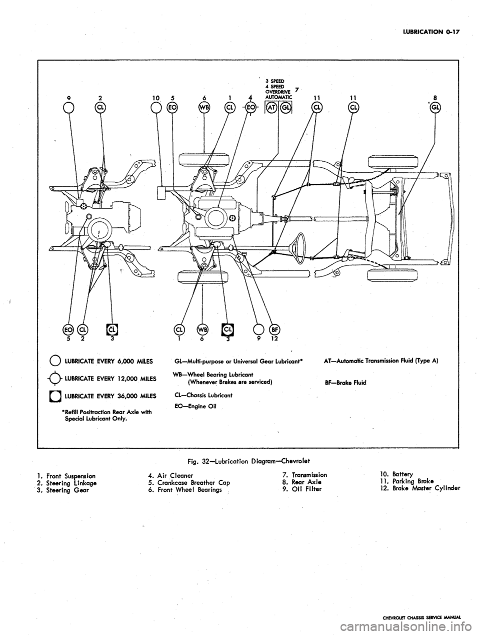
LUBRICATION 0-17
LUBRICATE EVERY 6,000 MILES
LUBRICATE EVERY 12,000 MILES
LUBRICATE EVERY 36,000 MILES
Refill Positraction Rear Axle with
Special Lubricant Only.
GL—Multi-purpose
or
Universal Gear Lubricant4
WB-Wheel Bearing Lubricant
(Whenever Brakes are serviced)
CL—Chassis Lubricant
EO-EngineOil
AT-Automatic Transmission Fluid {Type
A)
BF-Brake Fluid
Fig.
32—Lubrication Diagram—Chevrolet
1.
Front Suspension
2.
Steering Linkage
3. Steering Gear
4.
Air Cleaner
5. Crankcase Breather Cap
6. Front Wheel Bearings
7. Transmission
8. Rear Axle
9. Oil Filter
10.
Battery
11.
Parking Brake
12.
Brake Master Cylinder
CHEVROLET CHASSIS SERVICE MANUAL
Page 20 of 659
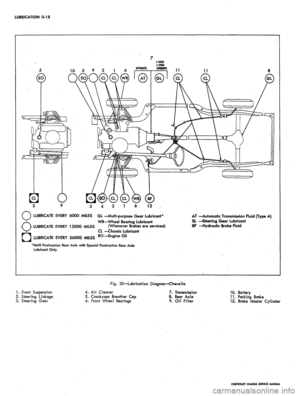
LUBRICATION 0-18
12
LUBRICATE EVERY 6000 MILES GL -Multi-purpose Gear Lubricant*
WB—Wheel Bearing Lubricant
LUBRICATE EVERY 12000 MILES (Whenever Brakes are serviced)
CL —Chassis Lubricant
LUBRICATE EVERY 36000 MILES E°-En9ine°il
"Refill Positraction Rear Axle with Special Positraction Rear Axle
Lubricant Only.
AT —Automatic Transmission Fluid (Type A)
SL —Steering Gear Lubricant
BF -Hydraulic Brake Fluid
1.
Front Suspension
2.
Steering Linkage
3. Steering Gear
Fig.
33—Lubrication Diagram—Chevelle
4.
Air Cleaner
5. Crankcase Breather Cap
6. Front Wheel Bearings
7. Transmission
8. Rear Axle
9. Oil Filter
10.
Battery
11.
Parking Brake
12.
Brake Master CylincU
CHEVROLET CHASSIS SERVICE MANUAL
Page 21 of 659
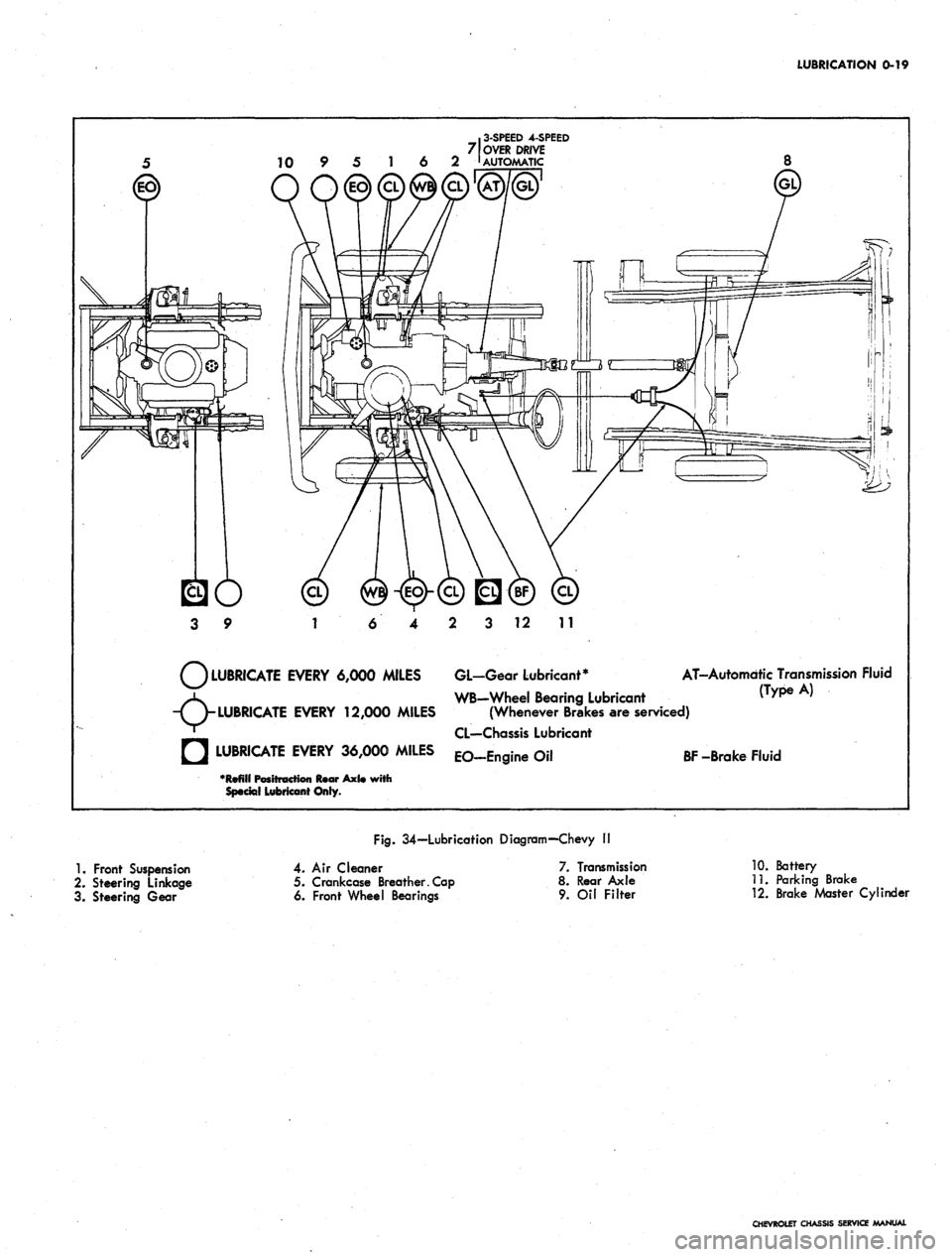
LUBRICATION
0-19
.
3-SPEED
4-SPEED
7 OVER DRIVE
10 9 5 1 6 2 '
AUTOMATIC
3 12 11
LUBRICATE EVERY 6,000 MILES GL-Gear Lubricant*
WB-Wheel Bearing Lubricant
(Wh Bk
AT-Automdtic Transmission Fluid
^ WB-Wheel Bearing Lubricant (Type A)
-TV
LUBRICATE
EVERY 12,000 MILES (Whenever Brakes are serviced)
' CL—Chassis Lubricant
• LUBRICATE EVERY 36,000 MILES EO_Engine Oil
BF
-Brake Fluid
•Refill Positt
Special Lubricant Only.
Axl«
with
1.
Front Suspension
2.
Steering Linkage
3. Steering Gear
Fig.
34—Lubrication Diagram—Chevy I!
4. Air Cleaner
5. Crankcase Breather. Cap
6. Front Wheel Bearings
7. Transmission
8. Rear Axle
9.
Oil Filter
10.
Battery
11.
Parking Brake
12.
Brake Master Cylinder
CHEVROLET CHASSIS SERVICE MANUAL
Page 22 of 659
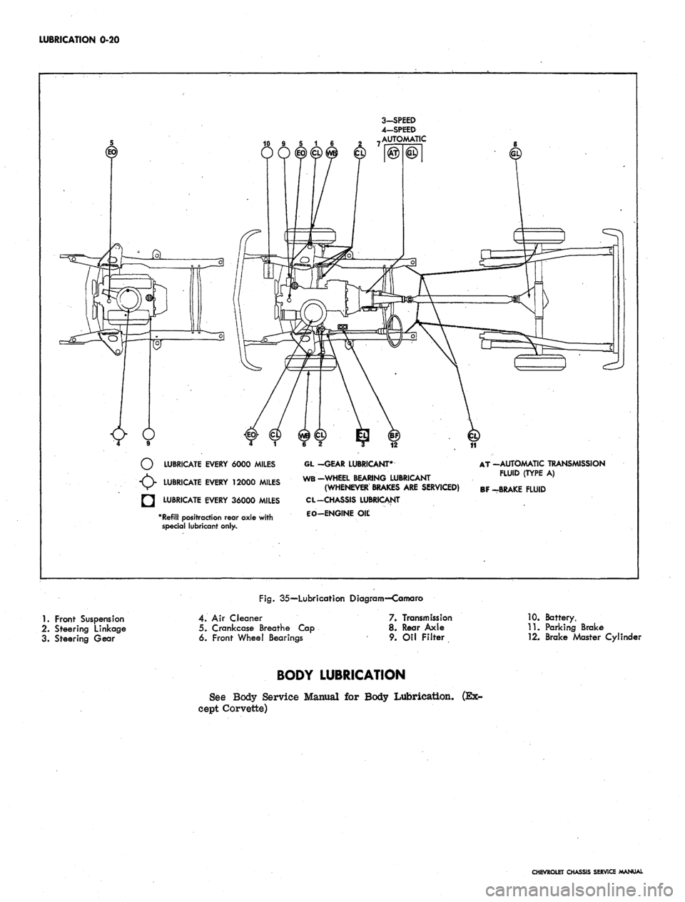
LUBRICATION 0-20
3-SPEED
4—SPEED
AUTOMATIC
LUBRICATE EVERY 6000 MILES
LUBRICATE EVERY 12000 MILES
LUBRICATE EVERY 36000 MILES
*
Refill
positraction rear axle with
special lubricant only.
GL -GEAR LUBRICANT*
WB-WHEEL BEARING LUBRICANT
(WHENEVER BRAKES
ARE
SERVICED)
CL -CHASSIS LUBRICANT
CO-ENGINE
Oil;
AT -AUTOMATIC TRANSMISSION
FLUID (TYPE
A)
BF -BRAKE FLUID
Fig.
35—Lubricafion Diagram—Camaro
1.
Front Suspension
2.
Steering Linkage
3. Steering Gear
4.
Air Cleaner
5. Crankcase Breathe Cap
6. Front Wheel Bearings
7. Transmission
8. Rear Axle
9. Oil Filter
10.
Battery,
11.
Parking Brake
12.
Brake Master Cylinder
BODY LUBRICATION
See Body Service Manual
for
Body Lubrication,
cept Corvette)
(Ex-
CHEVROLET CHASSIS SERVICE MANUAL
Page 23 of 659
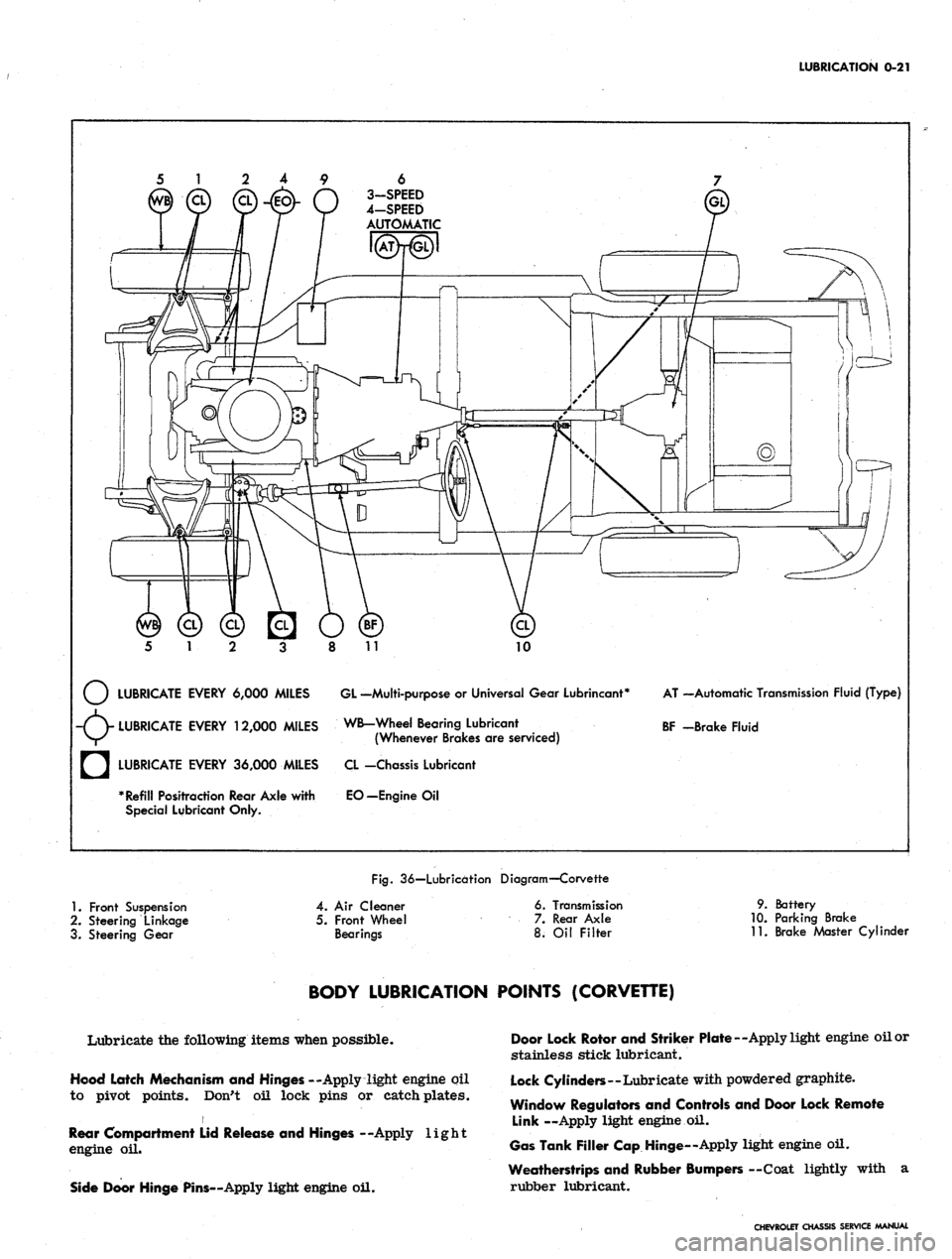
LUBRICATION
0-21
6
3-SPEED
4-SPEED
AUTOMATIC
10
LUBRICATE EVERY 6,000 MILES GL -Multi-purpose
or
Universal Gear Lubrincant*
-(V LUBRICATE EVERY 12,000 MILES WB-Wheel Bearing Lubricant
V/^ (Whenever Brakes
are
serviced)
AT —Automatic Transmission Fluid (Type)
BF -Brake Fluid
a
LUBRICATE EVERY 36,000 MILES
* Refill Positraction Rear Axle with
Special Lubricant Only.
CL -Chassis Lubricant
EO—Engine
Oil
Fig.
36—Lubrication Diagram—Corvette
1.
Front Suspension
2.
Steering Linkage
3. Steering Gear
4.
Air
Cleaner
5. Front Wheel
Bearings
6. Transmission
7. Rear Axle
8.
Oil
Filter
9. Battery
10.
Parking Brake
11.
Brake Master Cylinder
BODY LUBRICATION POINTS (CORVETTE)
Lubricate the following items when possible.
Hood Latch Mechanism and Hinges --Apply light engine oil
to pivot points. Don't oil lock pins or catch plates.
i
Rear Compartment Lid Release and Hinges --Apply light
engine
oil.
Side Door Hinge Pins—Apply light engine oil.
Door Lock Rotor and Striker Plate—Apply light engine oil or
stainless stick lubricant.
Lock Cylinders—Lubricate with powdered graphite.
Window Regulators and Controls and Door Lock Remote
Link —Apply light engine
oil.
Gas Tank Filler Cap Hinge—Apply light engine oil.
Weatherstrips and Rubber Bumpers —Coat lightly with
a
rubber lubricant.
CHEVROLET CHASSIS SERVICE MANUAL
Page 161 of 659
SECTION 2
FRAME
INDEX
Page
General Description 2-1
Chevrolet 2-1
Cheveile '. 2-1
Repair Procedures 2-1
Page
Checking Frame Alignment 2-1
Car Preparation 2-1
Tramming Sequence 2-1
Reference Point Dimensions 2-1
GENERAL DESCRIPTION
CHEVROLET AND CHEVELLE
Frames used on Chevrolet and Cheveile lines are basi-
cally the same, consisting of full length right and left
side members joined laterally by crossmembers. Sev-
eral different frames are used in each line to meet the
various vehicle size and function requirements but the
basic shape for each line remains the same. Differences
between frames in a given line exist only in metal gauge,
part size and numbers of parts necessary to meet the
particular structural requirements of the models
involved.
CORVETTE
The Corvette frame is a rigid perimeter unit, with five
crossmembers. From the rear kick-up forward, trap-
azoidal shaped, closed side members outline and protect
the passenger compartment. At the cowl area, the side
members curve inward in a sweeping "S" shape, to pro-
vide a sturdy foundation for the engine mounts and clear-
ance for front wheel movement. From the kick-up
rearward, box-sectioned side rails provide fore and aft
support for the rear axle and suspension. Lateral sup-
port is provided by five variously shaped welded-in
crossmembers, including the front unit, which formerly
was bolted-in.
CHEVY II AND CAMARO
Underbody alignment checking procedures will be found
in the Body Service Manual.
REPAIR PROCEDURES
CHECKING FRAME ALIGNMENT
Vehicles involved in an accident of any nature which
might result in a "swayed" or "sprung" frame should
always be checked for proper frame alingment in addi-
tion to steering geometry and wheel alignment.
CAR PREPARATION
Preparing the car for the frame alignment check in-
volves the following:
1.
Place the car on level surface.
2.
The weight of the car should be supported at the
wheel locations.
3.
A visual damage inspection should be made to elim-
inate needless measuring. Obviously damaged or
misaligned areas can often be located by sight.
TRAMMING SEQUENCE
When checking a frame for alignment in case of dam-
age,
the first step is horizontal "X" checking with a
tram from similar given points on opposite side of the
frame.
Frame alignment checks on all models should be made
with the tram points set at the center of each locating
point indicated and the cross bar level to insure
accuracy.
When "X" checking any section of the frame, the
measurements should agree within 3/16". If they do not,
it means that corrections will have to be made.
If a tram gauge is not available, the "plumb bob"
method of checking may be used. To assure any degree
of accuracy when using this method, the vehicle should
be on a level floor.
By using this method, it is only necessary to have a
#
piece of cord attached to an ordinary surveyor's plumb
bob.
When measuring the distance between two points,
the free end of the cord should be placed on the reference
point allowing the plumb bob to hang on the floor. A check
mark should be made on the floor just under the tip of
the plumb bob. This operation should be repeated at all
reference points. With these points located on the floor,
they may easily be measured with a rule.
The second step is checking the vertical dimensions
from the datum plane to the points to be trammed. With
the proper settings the tram bar will be on a plane
parallel to that of the frame. The exception to this would '
be when one of the reference locations is included in the
misaligned area; then the parallel plane between the
frame and the tram bar may not prevail. After com-
pletion of the repairs, the tram gauge should be set at
the specified dimension to check the accuracy of the re-
pair operation.
ALIGNMENT REFERENCE POINT DIMENSIONS
Dimensions to holes are measured to dead center of
the holes and flush to the adjacent surface metal.
CHEVROLET CHASSIS SERVICE MANUAL
Page 165 of 659
SECTION
3
FRONT SUSPENSION
INDEX
Page
General Description
. . . . 3-1
Maintenance and Adjustments
3-3
Front Wheel Bearing Adjustment
3-3
Front End Alignment
3-5 .
Alignment Preliminary Steps ............
3-5
Caster
and
Camber Adjustments
. . 3-5
Chevelle, Caxnaro
and
Corvette
3-5
Chevrolet and Chevy
II 3-6
Steering Axis Inclination
3-6
Toe-in Adjustment
3-6
Cornering Wheel Relationship
3-6
Riding Heigit
and
Coil Spring Sag
3-7
Repair Procedures
3-8
Front Brake Drum (Chevrolet, Camaro, Chevelle,
Chevy E)
. . 3-8
Removal
3-8
Installation
3-8
Front Wheel Hub
3-8
Replacement
. . . . . 3-8
Replacement
of
Hub Wheel Bolts
3-8
Front Wheel Bearings
. . 3-8
Removal
3-8
Inspection
3-9
Repairs
. . 3-9
Replacement
of
Bearing Cups
3-9
Installation
3-9
Steering Knuckle
. . . 3-9
Removal
3-9
Installation
3-9
Shock Absorber
3-10
Chevrolet, Chevelle, Camaro
and
Corvette
3-10
Removal
, . 3-10
Installation
3-10
Chevy
It 3-11
Removal
3-11
Installation
3-11
Stabilizer
Bar 3-11
Removal
3-11
Installation
3-11
Strut Rod
3-11
Chevrolet and Chevy
II 3-11
Removal
3-11
Installation
3-12
Front Coil Springs
3-12
Chevrolet
3-12
Removal
3-12
Installation
3-13
Chevelle
and
Camaro
3-13
Removal
3-13
Installation
3-14
Chevy H
3-14
Removal
3-14
Spring Seat Disassembly and Assembly
3-15
Installation
3-15
Corvette
3-15
Lower Control Arm Spherical Joint
.' 3-16
Chevrolet, Chevelle, Camaro and
Corvette
3-16
Inspection
. 3-16
Chevrolet and Corvette
3-16
Removal
3-16
Installation
3-16
Page
Chevelle
and
Camaro
3-17
Removal
3-17
Installation
. . . . 3-17
Chevy
II 3-17
Inspection
. 3-17
Removal
3-17
Installation
3-17
Lube Fittings
3-18
Lower Control Arm
. . . . 3-18
Chevrolet
. 3-18
Removal
3-18
Installation
3-18
Chevelle and Camaro
3-18
Removal
3-18
Installation
3-18
Chevy H
3-18
Removal
3-18
Installation
3-19
Corvette
3-19
Removal
3-19
mstallation
3-19
Lower Control Arm Bushings
3-20
Chevrolet
3-20
Removal
3-20
Installation
3-20
Chevelle and Camaro
. 3-20
Removal
3-20
Installation
3-20
Chevy H
3-21
Removal
* 3-21
InstaEation
3-21
Cross Shaft and/or Bushings
. 3-21
Corvette
3-21
Removal
3-21
Installation
3-21
Upper Control Arm Spherical Joint
3-21
Chevrolet, Chevelle, Camaro and Corvette
..... 3-21
Inspection.
3-21
Replacement
3-21
Chevy
II 3-21
Inspection
3-21
Replacement
3-21
Lube Fittings
3-22
Upper Control Arm
3-22
Chevrolet, Chevelle, Camaro
and
Corvette
3-22
Removal
3-22
Installation
3-22
Chevy H
3-22
Removal
3-22
Installation
3-23
Upper Control Arm Cross Shaft
and/or Bushings
3-23
Chevrolet, Camaro and Chevelle
3-23
Removal
. 3-23
Installation
3-23
Chevy H
3-24
Removal
3-24
Installation
. . . 3-25
Corvette
3-25
Removal
3-25
Installation
3-25
Special Tools
3-26
Specifications
...'..'
At rear of Book
GENERAL DESCRIPTION
The 1967 Chevrolet, Chevelle, Camaro, Chevy n and
Corvette front suspension systems are basically similar,
being of the
S.L.A.
(short-long arm) type with independent
coil springs. In the Chevrolet, Chevelle, Camaro and
Corvette the springs ride on the lower control arms; in
the Chevy II the springs ride on the upper control arms.
Spherical joints connect the upper and lower arms to the
steering knuckle. Tapered roller wheel bearings are
used.
Camber angle is adjusted, on the Chevrolet and Chevy n
CHEVROLET CHASSIS SERVICE MANIM
Page 172 of 659
FRONT SUSPENSION 3-8
REPAIR PROCEDURES
Unless otherwise indicated all repair procedures will
apply to all five vehicles covered in this manual.
CAUTION: During any operations which in-
clude breaking the ball stud loose from the
knuckle boss extreme care must be used to as-
sure that the ball stud seal is not damaged or
cut. A recommended way to loosen the stud is to
place a flat bar stock against the knuckle boss
and strike the bar rather than the knuckle.
FRONT BRAKE DRUM-CHEVROLET, CAMARO,
CHEVELLE, CHEVY It
Removal
1.
Remove hub caps, partially loosen wheel nuts and
raise vehicle from floor. Remove wheel nuts and
wheel.
2.
Remove brake drum. In some cases it may be nec-
essary to back off brake adjustment because of
scored drum or unevenly worn brake linings.
3.
Check brake drum for concentricity, damaged pilot
diameter or scored braking surface. Lightly sand
braking surface and wipe clean.
Installation
1.
Install drum over hub bolts making sure alignment
dowel on drum web indexes with hole in wheel hub.
This will assure proper drum alignment with hub
bolts and hub pilot diameter.
2.
Install wheel and partially tighten wheel nuts.
3.
Re-adjust brake shoes to original setting. It may be
necessary to re-adjust brake shoes on both front
and/or rear wheels to assure balanced brake adjust-
ment. See Section 5 for brake adjustment procedure.
4.
Lower vehicle to floor, tighten hub wheel nuts and in-
stall hub cap.
FRONT WHEEL HUB
Replacement
1.
Remove hub caps, break loose the wheel stud nuts
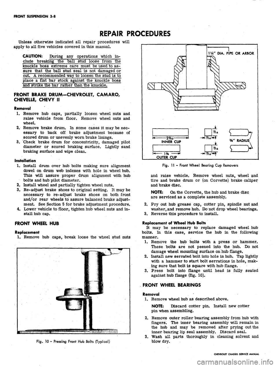
VM" DIA. PIPE OR ARBOR
>l
INNER CUP
OUTER CUP
JL
RADIUS
e^
Fig.
10 - Pressing Front Hub Bolts (Typical)
Fig.
11 - Front Wheel Bearing Cop Removers
and raise vehicle. Remove wheel nuts, wheel and
tire and brake drum or (on Corvette) brake caliper
and brake disc.
NOTE:
On the Corvette, the hub and brake disc
are serviced as a complete assembly.
2.
Pry out hub grease cap, cotter pin, spindle nut and
washer,
and
remove hub. Do not drop wheel bearings.
3.
Reverse this procedure to install.
Replacement of Wheel Hub Bolts
It may be necessary to replace damaged wheel hub
bolts.
In this case, service the hub in the following
manner.
1.
Remove the hub bolts with a press or hammer.
These bolts are not peened into the hub. Do not
damage wheel mounting surface on hub flange.
2.
Install new serrated bolt into hole in
hub.
Tap lightly
with a hammer to start bolt serrations in hole, mak-
ing sure that bolt is square with hub flange.
3.
Press bolt into flange until head is fully seated
against hub flange (fig. 10).
FRONT WHEEL BEARINGS
Removal '
1.
Remove wheel hub as described above.
NOTE: Discard cotter pin. Install new cotter
pin when assembling.
2.
Remove outer roller bearing assembly from hub with
fingers. The inner bearing assembly will remain in
the hub and may be removed after prying out the
inner bearing lip seal assembly. Discard seal.
3.
Wash all parts thoroughly in cleaning solvent and
blow dry.
CHEVROLET CHASSIS SERVICE MANUAL
Page 173 of 659
FRONT SUSPENSION 3-9
Inspection
1.
Check bearings for cracked separators or worn or
pitted rollers and races.
2.
Check brake drum for
out-of-
round or scoring.
3.
Check fit of bearing outer cups in hub.
Repairs
Replacement of Bearing Cups
1.
Using steel bar stock, make press-out tools shown in
Figure 11.
2.
Insert removers through hub, indexing ends into slots
in hub shoulder behind bearing cup.
3.
Using a suitable extension pipe or rod, press bearing
cups from hub.
4.
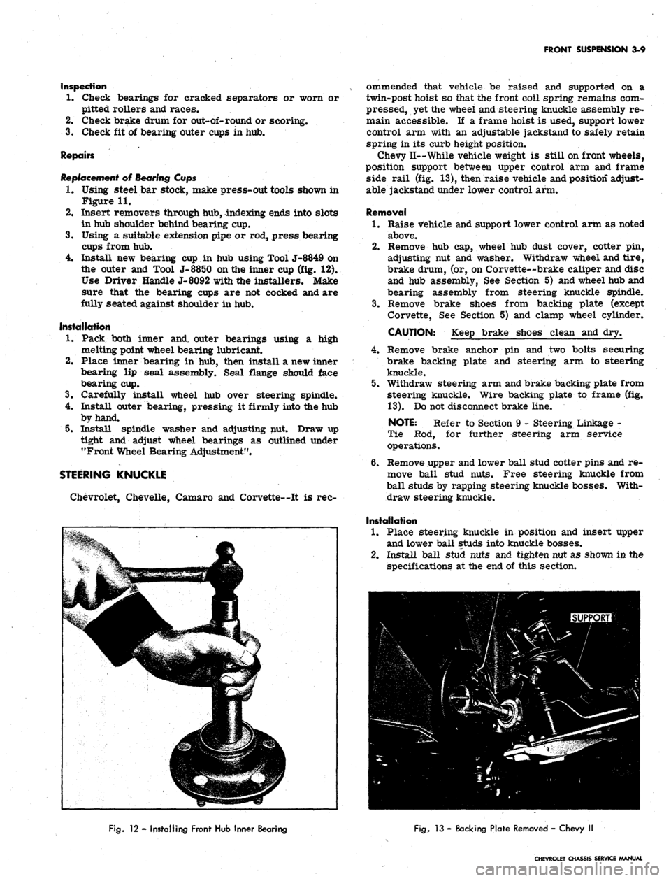
Install new bearing cup in hub using Tool J-8849 on
the outer and Tool J-8850 on the inner cup (fig. 12).
Use Driver Handle J-8092 with the installers. Make
sure that the bearing cups are not cocked and are
fully seated against shoulder in hub.
Installation
1.
Pack both inner and. outer bearings using a high
melting point wheel bearing lubricant.
2.
Place inner bearing in hub, then install a new inner
bearing lip seal assembly. Seal flange should face
bearing cup.
3.
Carefully install wheel hub over steering spindle.
4.
Install outer bearing, pressing it firmly into the hub
by hand.
5.
Install spindle washer and adjusting nut. Draw up
tight and adjust wheel bearings as outlined under
"Front Wheel Bearing Adjustment".
STEERING KNUCKLE
Chevrolet, Chevelle, Camaro and Corvette—It is rec-
ommended that vehicle be raised and supported on a
twin-post hoist so that the front coil spring remains com-
pressed, yet the wheel and steering knuckle assembly re-
main accessible. If a frame hoist is used, support lower
control arm with an adjustable jackstand to safely retain
spring in its curb height position.
Chevy n— While vehicle weight is still on front wheels,
position support between upper control arm and frame
side rail (fig. 13), then raise vehicle and position adjust-
able jackstand under lower control arm.
Removal
1.
Raise vehicle and support lower control arm as noted
above.
2.
Remove hub cap, wheel hub dust cover, cotter pin,
adjusting nut and washer. Withdraw wheel and tire,
brake drum, (or, on Corvette--brake caliper and disc
and hub assembly, See Section 5) and wheel hub and
bearing assembly from steering knuckle spindle.
3.
Remove brake shoes from backing plate (except
Corvette, See Section 5) and clamp wheel cylinder.
CAUTION: Keep brake shoes clean and dry.
4.
Remove brake anchor pin and two bolts securing
brake backing plate and steering arm to steering
knuckle.
5.
Withdraw steering arm and brake backing plate from
steering knuckle. Wire backing plate to frame (fig.
13).
Do not disconnect brake line.
NOTE: Refer to Section 9 - Steering Linkage -
Tie Rod, for further steering arm service
operations.
6. Remove upper and lower ball stud cotter pins and re-
move ball stud nuts. Free steering knuckle from
ball studs by rapping steering knuckle bosses. With-
draw steering knuckle.
Installation
1.
Place steering knuckle in position and insert upper
and lower ball studs into knuckle bosses.
2.
Install ball stud nuts and tighten nut as shown in the
specifications at the end of this section.
Fig.
12 - Installing Front Hub Inner Bearing
Fig.
13 - Backing Plate Removed - Chevy II
CHEVROLET CHASSIS SERVICE MANUAL
Page 191 of 659
SECTION
4
REAR SUSPENSION
AND
DRIVE LINE
CONTENTS
OF
THIS SECTION
Page
Rear Suspension
4-1
Drive Line.
. 4-26
Rear Axle ......
4-26
Propeller Shaft
and
Universal Joints
Special Tools
4-37
4-43
REAR SUSPENSION
INDEX
General Description
4-1
Chevrolet
4-1
Chevelle
4-1
Chevy
n and
Camaro
. . . . . 4-2
Corvette
. . . . . . 4-3
Maintenance
and
Adjustments ...............
4-4
Riding Height Check (Chevrolet, Camaro,
Chevelle
and
Chevy
II) 4-5
Wheel Alignment (Corvette)
4-5
Wheel Bearing Adjustment (Corvette)
4-6
Component Parts Replacement (Chevrolet, Camaro,
Chevelle
and
Chevy
JJ) 4-7
Coil Spring
4-7
Chevrolet
4-7
Removal
4-7
Installation
4-7
Chevelle
4-8
Removal
4-8
4-8
Installation
.
Leaf Spring, Spring Seat Pads, Spring
Eye
Bushings
4-9
Chevy
H 4-9
Removal
4-9
Installation
4-9
Camaro
4-10
Removal
4-10
Installation
4-11
Shock Absorber
4-11
Chevrolet
and
Chevelle
. 4-11
Removal
4-11
Installation
. . 4-12
Chevy
II 4-12
Removal
4-12
Installation
4-rl2
Camaro
4-12
Removal
. 4-12
Installation
4-12
Control
Arm . . 4-12
Chevrolet Upper
4-12
Removal
. 4-12
Page
Bushing Replacement
. 4-13
Installation
4-14
Chevrolet Lower
4-14
Removal
4-14
Bushing Replacement
4-14
Installation
. 4-15
Chevelle Upper
and
Lower.
. 4-15
Removal
4-15
Bushing Replacement
4-15
Installation
4-17
Rear Suspension
Tie Rod
(Chevrolet)
. . .
......
. . . 4-17
Removal
4-17
Bushing Replacement
4-17
Installation
4-17
Component Parts Replacement (Corvette)
. . 4-17
Wheel Spindle
and
Support
4-17
Removal
4-17
Repairs
', . 4-17
Installation
4-18
Differential Carrier Support Bracket Replacement.
. 4-20
Shock Absorber
4-20
Removal
4-20
Installation
* .... 4-20
Strut
Rod and
Bracket
4-20
Removal
4-20
Repairs
4-21
Installation
4-21
Spring
4-21
Removal
4-21
Repairs
4-22
Installation
4-22
Torque Control
Arm 4-23
Removal
4-23
Repairs
. 4-23
Installation
4-24
Suspension Crossmember
4-24
Removal
4-24
Repairs—Isolation Mount
4-25
Installation
4-25
Stabilizer Shaft Replacement
4-25
GENERAL DESCRIPTION
CHEVROLET
The link type rear suspension (fig. 1) has two lower
control arms which maintain proper axle to frame re-
lationship and also take the acceleration, drive and
braking forces. A single upper control arm on light-
duty models (or two upper control arms on heavy-duty
models and all station wagons) limits axle rotation when
drive, acceleration or braking forces are applied. Lateral
movement of the axle is restricted by the axle-to-frame
tie rod. Two full coil springs and two direct, double
acting shock absorbers are provided for additional ride
control.
CHEVELLE
The rear suspension (fig. 2) is of the four-link design
utilizing axle mounted, full coil springs and direct,
double-acting shock absorbers.
Two rubber-bushed lower control arms, stretching
slightly outboard from axle-mounted brackets to frame
side member mounted brackets, maintain fore and aft
CHEVROLET CHASSIS SERVICE MANUAL