transmission oil CHEVROLET CAMARO 1967 1.G Chassis User Guide
[x] Cancel search | Manufacturer: CHEVROLET, Model Year: 1967, Model line: CAMARO, Model: CHEVROLET CAMARO 1967 1.GPages: 659, PDF Size: 114.24 MB
Page 228 of 659
REAR SUSPENSION
AND
DRIVE LINE
4-38
•"•f •--..—-.>•,«.-. ^
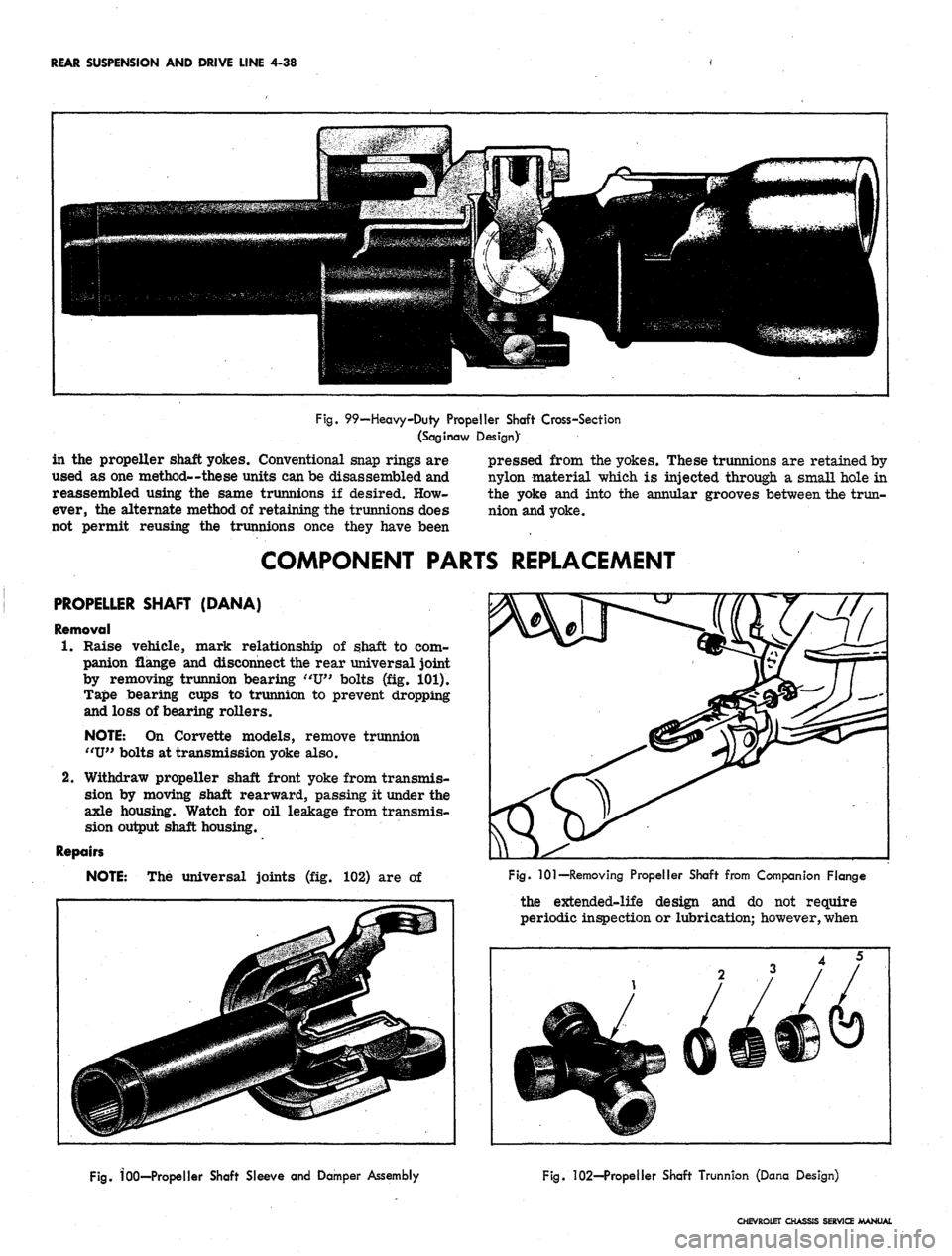
Fig. 99—Heavy-Duty Propeller Shaft Cross-Section
(Saginaw Design)'
in
the
propeller shaft yokes. Conventional snap rings are
used
as
one method—these units can be disassembled and
reassembled using
the
same trunnions
if
desired.
How-
ever, the alternate method
of
retaining the trunnions does
not permit reusing
the
trunnions once they have been
pressed from the yokes. These trunnions are retained by
nylon material which
is
injected through
a
small hole
in
the yoke and into
the
annular grooves between the trun-
nion and yoke.
COMPONENT PARTS REPLACEMENT
PROPELLER SHAFT (DANA)
Removal
1.
Raise vehicle, mark relationship
of
shaft
to com-
panion flange and disconnect the rear universal joint
by removing trunnion bearing "U" bolts
(fig. 101).
Tape bearing cups
to
trunnion
to
prevent dropping
and loss of bearing rollers.
NOTE:
On
Corvette models, remove trunnion
"U"
bolts at transmission yoke also.
2.
Withdraw propeller shaft front yoke from transmis-
sion
by
moving shaft rearward, passing
it
under the
axle housing. Watch
for oil
leakage from transmis-
sion output shaft housing.
Repairs
NOTE:
The
universal joints
(fig. 102) are of
Fig.
101—
Removing Propeller Shaft from Companion Flange
the extended-life design
and do not
require
periodic inspection or lubrication; however, when
Fig.
100—Propeller Shaft Sleeve
and
Damper Assembly
Fig. 102—Propeller Shaft Trunnion (Dana Design)
CHEVROLET CHASSIS SERVICE MANUAL
Page 230 of 659
REAR SUSPENSION AND DRIVE LINE 4-40
Fig.
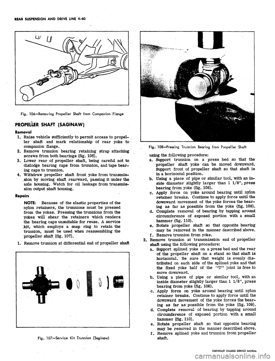
106—Removing Propeller Shaft from Companion Flange
PROPELLER SHAFT (SAGINAW)
Removal
1.
Raise vehicle sufficiently to permit access to propel-
ler shaft and mark relationship of rear yoke to
companion flange.
2.
Remove trunnion bearing retaining strap attaching
screws from both bearings (fig. 106).
3.
Lower rear of propeller shaft, being careful not to
dislodge bearing caps from trunnion, and tape bear-
ing caps to trunnion.
4.
Withdraw propeller shaft front yoke from transmis-
.sion by moving shaft rearward, passing it under the
axle housing. Watch for oil leakage from transmis-
sion output shaft housing.
Repairs
NOTE:
Because of the elastic properties of the
nylon retainers, the trunnions must be pressed
from the yokes. Pressing the trunnions from the
yokes will shear the retainers which renders
the bearing caps unsuitable for reuse. A service
Jdt, which employs a snap ring to retain the
trunnion, must be used when reassembling the
propeller shaft (fig. 107).
1.
Remove trunnion at differential end of propeller shaft
Fig.
107—Service Kir Trunnion (Saginaw)
Fig.
108—Pressing Trunnion Bearing from Propeller Shaft
using the following procedure:
a. Support trunnion on a press bed so that the
propeller shaft yoke can be moved downward.
Support front of propeller shaft so that shaft is
in a horizontal position.
b.
Using a piece of pipe or similar tool, with an ins-
side diameter slightly larger than 1 1/8", press
bearing from yoke (fig. 108).
c. Apply force on yoke around bearing until nylon
retainer breaks. Continue to apply force until the
downward movement of the yoke forces the bear-
ing as far as possible from the yoke (fig. 109).
d. Complete removal of bearing by tapping around
circumference of exposed portion with a small
hammer (fig. 110).
e. Rotate propeller shaft so that opposite bearing
-may be removed in the manner described above.
f. Remove trunnion from yoke.
Remove trunnion at transmission end of propeller
shaft using the following procedure:
a. Support splined yoke on a press bed and the rear
of the propeller shaft on a stand so that shaft is
horizontal. Be sure that weight is evenly dis-
tributed on each side of the splined yoke and that
the fixed yoke half of the "U" joint is free to
move downward.
b.
Using a piece of pipe or similar tool, with an
inside diameter slightly larger than 1 1/8", press
bearing from yoke (fig. 108).
c. Apply force on yoke around bearing until nylon
retainer breaks. Continue to apply force until the
downward movement of the yoke forces the bear-
ing as far as possible from the yoke (fig. 109).
d. Complete removal of bearing by tapping around
circumference of exposed portion with a small
hammer (fig. 110).
e. Rotate propeller shaft so that opposite bearing
may be removed in the manner described above.
f. Remove splined yoke and trunnion from propeller
shaft.
CHEVROLET CHASSIS SERVICE MANUAL
Page 271 of 659
ENGINE 6-6
CHOKE VALVE
COMPLETELY
CLOSED
PULL UPWARD ON
ROD TO END OF
TRAVEL
BEND ROD
TO ADJUST
ROD IN BOTTOM
OF SLOT
BOTTOM OF
ROD SHOULD
EVENWITH
TOP OF
HOLE
CHOKE VALVE
CLOSED
BOTTOM OF
ROD SHOULD
BE EVEN WITH
TOP OF HOLE
TOP OF ROD
SHOULD BE EVEN
WITH BOTTOM
OF HOLE (CHOKE
CLOSED)
^..BEND ROD TO
ADJUST
_PULL DOWNWARD
ON ROD TO CON-
TACT STOP
L6 (TYPICAL)
V8 327-275 HP
V8 350-295 HP
BEND ROI
TO ADJUST
PULL UPWARD ON
ROD TO CONTACT
STOP ON BRACKET
ALL V8 (EXCEPT 327-275 HP
AND 350-295 HP)
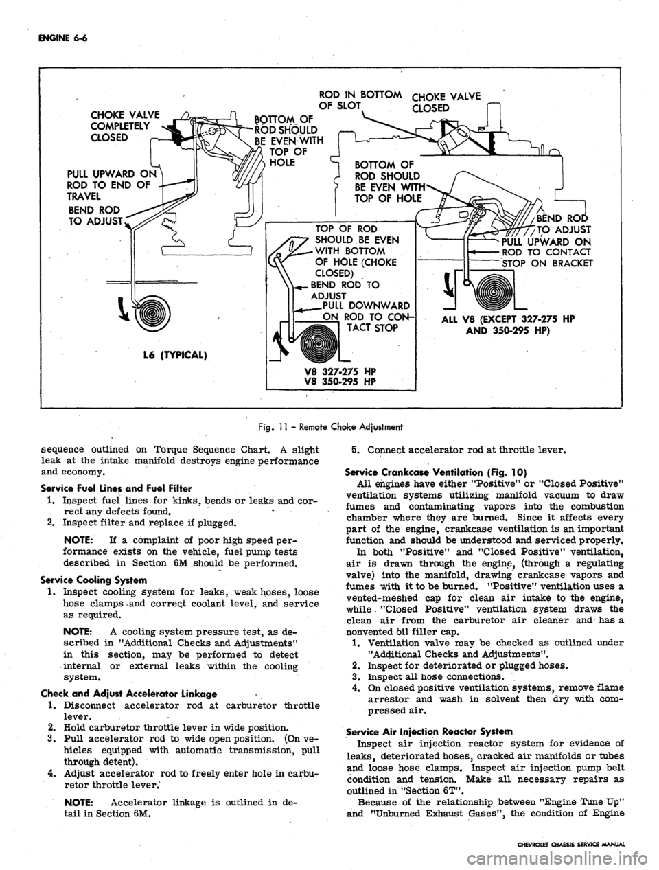
Fig.
11 - Remote Choke Adjustment
sequence outlined on Torque Sequence Chart. A slight
leak at the intake manifold destroys engine performance
and economy.
Service Fuel Lines and Fuel Filter
1.
Inspect fuel lines for kinks, bends or leaks and cor-
rect any defects found, • • •
2.
Inspect filter and replace if plugged.
NOTE:
If a complaint of poor high speed per-
formance exists on the vehicle, fuel pump tests
described in Section 6M should be performed.
Service Cooling System
1.
Inspect cooling system for leaks, weak hoses, loose
hose clamps and correct coolant level, and service
as required.
NOTE:
A cooling system pressure test, as de-
scribed in "Additional Checks and Adjustments"
in this section, may be performed to detect
internal or external leaks within the cooling
system.
Check and Adjust Accelerator Linkage
1.
Disconnect accelerator rod at carburetor throttle
lever.
2.
Hold carburetor throttle lever in wide position.
3.
Pull accelerator rod to wide open position. (On ve-
hicles equipped with automatic transmission, pull
through detent).
4.
Adjust accelerator rod to freely enter hole in carbu-
retor throttle lever.'
NOTE:
Accelerator linkage is outlined in de-
tail in Section 6M.
5. Connect accelerator rod at throttle lever.
Service Crankcase Ventilation (Fig. 10}
All engines have either "Positive" or "Closed Positive"
ventilation systems utilizing manifold vacuum to draw
fumes and contaminating vapors into the combustion
chamber where they are burned. Since it affects every
part of the engine, crankcase ventilation is an important
function and should be understood and serviced properly.
In both "Positive" and "Closed Positive" ventilation,
air is drawn through the engine, (through a regulating
valve) into the manifold, drawing' crankcase vapors and
fumes with it to be burned. "Positive" ventilation uses a
vented-meshed cap for clean air intake to the engine,
while . "Closed Positive" ventilation system draws the
clean air from the carburetor air cleaner and has a
nonvented oil filler cap.
1.
Ventilation valve may be checked as outlined under
"Additional Checks and Adjustments".
2.
Inspect for deteriorated or plugged hoses.
3.
Inspect all hose connections.
4.
On closed positive ventilation systems, remove flame
arrestor and wash in solvent then dry with com-
pressed air.
Service Air Injection Reactor System
Inspect air injection reactor system for evidence of
leaks,
deteriorated hoses, cracked air manifolds or tubes
and loose hose clamps. Inspect air injection pump belt
condition and tension. Make all necessary repairs as
outlined in "Section 6T".
Because of the relationship between "Engine Tune Up"
and "Unburned Exhaust Gases", the condition of Engine
CHEVROLET CHASSIS SERVICE MANUAL
Page 273 of 659
ENGINE
6-8
Check
and
Adjust Ignition Timing
(Fig. 13)
1.
Disconnect
the
distributor spark advance hose
and
plug
the
vacuum source opening.
2.
Start engine
and run at
idle speed
(see
tune
up
chart).
3.
Aim
timing light
at
timing
tab.
NOTE:
- The
markings
on the
tabs
are in 2°
increments
(the
greatest number
of
markings
on
the
"A"
side
of the "O"). the "O"
markings
is
TDC
of
#1 cylinder
and all
BTDC settings fall
on
the
"A"
(advance) side
of "O".
4.
Adjust
the
timing
by
loosening
the
distributor clamp
and
,
rotating
the
distributor body
as
required, then
tighten
the
clamp.
5.
Stop engine
and
remove timing light
and
reconnect
the spark advance hose.
Adjust Idle Speed
and
Mixture
(Fig. 14)
(Except when
equipped with
Air
Injection Reactor System)
1.
As a
preliminary adjustment, turn idle mixture
screws lightly
to
seat
and
back
out 2
turns.
CAUTION:
Do not
turn idle mixture screw
tightly against seat
or
damage
may
result.
2.
With engine running
at
operating temperature (choke
wide open) adjust idle speed screw
to
bring idle
speed
to
specified
rpm
(automatic transmission
in
drive, manual transmission
in
neutral).
3.
Adjust idle mixture screw
to
obtain highest steady
idle speed
(1/4
turn
out
from lean roll).
4.
Repeat Steps
2 and 3 as
needed
for
final adjustment.
5.
Shut down
the
engine, remove gauges
and
install
air
cleaner.
Adjust Idle Speed
and
Mixture
(Fig. 14)
(With
Air
Injection Reactor System)
The recommended adjustment procedure
for Air
Injec-
tion Reactor System equipped engines
is as
follows:
1.
As a
preliminary adjustment, turn idle mixture
screws lightly
to
seat
and
than back
out 3
turns.
CAUTION:
Do not
turn idle mixture screw
tightly against seat
or
damage
may
result.
2.
With engine running
at
operating temperature, choke
wide open,
and
parking brake applied, adjust idle
specified idle speed (automatic
"drive"-manual transmission
in
to
in
screw
transmission
"neutral").
;3.
Adjust idle mixture screw (turn
in) to
"lean roll"
position; then turn screw
out 1/4
turn
(1/4
turn rich
from "lean roll").
The
definition
of
"lean roll" point
is
a 20 to 30 rpm
drop
in
engine speed, obtained
by
leaning
the
idle mixture.
4.
Repeat Steps
2 and 3 as
needed
for
final adjustments.
ADDITIONAL CHECKS
AND
ADJUSTMENTS
Testing Crankcase Ventilation Valve
(Fig. 15) 0
1.
Connect tachometer
and
vacuum gauge
as for
idle
speed
and
mixture adjustment.
2.
Set
parking brake, start engine
and
adjust idle speed
and mixture.
3.
Disconnect ventilation hose
at
valve, block opening
of
valve
and
read engine
rpm
change.
4.
A
change
of
less than
50 rpm
indicates
a
plugged
ventilation valve
-
replace
the
valve.
Cylinder Balance Test
(Fig. 16)
It
is
often difficult
to
locate
a
weak cylinder.
A com-
pression test,
for
example, will
not
locate
a
leaky intake
manifold,
a
valve
not
opening properly
due to a
worn
camshaft,
or a
defective spark plug.
With
the
cylinder balance test,
the
power output
of one
cylinder
may be
checked against another, using
a set of
grounding leads. When
the
power output
of
each cylinder
is
not
equal,
the
engine will lose power
and run
roughly.
Perform
a
cylinder balance test
as
follows:
1.
Connect
the
tachometer
and
vacuum gauge.
2.
Start engine
and run at 1500 rpm.
3.
Ground large clip
of
grounding leads
and
connect
in-
dividual leads
to all
spark plugs except
the
pair being
tested.
Divide
the
firing order
in
half
and
arrange
one
half
over
the
other.
The
cylinders
to be
tested together
ap-
pear
one
over
the
other.
L4 Firing Order
V8 Firing Order
1-8-4-3-6-5-7-2
1-6, 8-5, 4-7, 3-2
1-3-4-2
= 1-3
4-2
L6 Firing Order
1-5-3-6-2-4
=
=
1-4. 3-2
1-5-3
6-2-4
1-6, 5-2, 3-4
1-8-4-3
6-5-7-2
4.
Operate engine
on
each pair
of
cylinders
in
turn
and
note engine
rpm and
manifold vacuum
for
each pair.
A variation
of
more than
1
inch
of
vacuum
or 40 rpm
between pairs
of
cylinders being tested indicates that
the cylinders
are off
balance.
Battery
The battery should
be
checked with special testing
equipment
and to the
equipment manufacturers specifica-
tions.
See
Section 6Y
for
complete information
on
battery
tests.
Ignition
The following additional ignition checks
may be
made
with
any of
several pieces
of
equipment available
for un-
covering
the
source
of
engine difficulties.
The
specific
operating instructions
of the
equipment manufacturer
should
be
followed:
Cranking voltage
Ignition switch
Distributor resistance
Secondary resistance
Ignition output
and
secondary leakage
Cranking Voltage
(Fig. 17)
1.
Disconnect coil primary lead
at the
coil negative
terminal
to
prevent engine from firing during
cranking.
2.
Connect voltmeter between primary terminal
of coi|
(resistance wire side)
and
ground.
3.
Operate starting motor.
CHEVROLET CHASSIS SERVICE MANUAL
Page 279 of 659
ENGINE 6-14
b.
Bolt transmission to engine, then raise engine and
transmission assembly and install flywheel to
converter attaching bolts.
c. Install converter
housing*
underpan and starter.
3.
Tilt and lower engine and transmission assembly into
the chassis as a unit, guiding engine to align front
mounts with frame supports.
4.
Install front mount through bolts and torque to
specifications.
5.
Raise engine enough to install rear crossmember,
then install crossmember, install rear mount, lower
engine and torque bolts to specifications.
6. Remove lifting device and lifting adapter then install
rocker arm cover as outlined.
7.
On synchromesh equipped vehicles, install clutch
cross shaft engine bracket, then adjust and connect
clutch as outlined in Section 7.
8. Connect:
• Speedometer cable.
• Shift linkage at transmission.
9; Install propeller shaft.
10.
Remove jack stands and lower vehicle.
11.
Connect:
Power steering pump lines (if disconnected).
Vacuum line to power brake unit (if disconnected).
Fuel line at fuel pump.
Exhaust pipe at manifold flange.
Accelerator linkage at manifold bellcrank.
12.
Connect wires at:
Coil
Oil pressure switch
Temperature switch
Delcotron
Starter solenoid
13.
Install pulley, fan blade and fan belt as outlined in
Section 6K.
14.
Install radiator and shroud as outlined in Section 13.
15.
Install and adjust hood as outlined in Section 11.
16.
Connect battery cables.
17.
Fill with coolant, engine oil and transmission oil,
then start engine and check for leaks.
18.
Perform necessary adjustments and install air
cleaner.
MANIFOLD ASSEMBLY
Removal
1.
Remove air cleaner.
2.
Disconnect both throttle rods at bellcrank and re-
move throttle return spring.
3.
Disconnect fuel and vacuum lines at carburetor.
Disconnect choke cable on \A engines.
4.
Disconnect crankcase ventilation hose at rocker arm
cover.
5.
Disconnect exhaust pipe at manifold flange and dis-
card packing.
6. Remove manifold attaching bolts and clamps then
remove manifold assembly and discard gaskets.
7.
Check for cracks in manifold castings.
8. If necessary to replace either intake or exhaust
manifolds, separate them by removing one bolt and
two nuts at center of assembly. Reassemble mani-
folds using a new gasket. Tighten finger tight and
torque to specifications after assembly to cylinder
head. Transfer all necessary parts.
Installation
1.
Clean gasket surfaces on cylinder head and
manifolds*
2.
Position new gasket over manifold end studs on head
and carefully install the manifold in position making
sure the gaskets are in place.
3.
Install bolts and clamps while holding manifold in
place with hand.
4.
Torque bolts to specifications.
NOTE: On L6 engines center bolt and end bolt
torque differ.
5.
Connect exhaust pipe to manifold using a new
packing.
6. Connect crankcase ventilation hose at rocker arm
cover.
7.
Connect fuel and vacuum lines at carburetor.
8. On L4 engines connect choke cable and adjust as out-
lines in Section 6M.
9. Connect throttle rods at bellcrank and install throttle
return spring.
10.
Install air cleaner, start engine, check for leaks and
adjust carburetor idle speed and mixture.
ROCKER ARM COVER
Removal
1.
Disconnect crankcase ventilation hose(s) at rocker
arm cover.
2.
Remove air cleaner.
3.
Disconnect temperature wire from rocker arm cover
clips.
4.
Remove rocker arm cover. '
CAUTION: Do Not pry rocker arm cover loose
Gaskets adhering to cylinder head and rocker
arm cover may be sheared by bumping end of
rocker arm cover rearward with palm of hand or
a rubber mallet.
Installation
1.
Clean gasket surfaces on cylinder head and rocker
arm cover with degreaser then, using anew gasket,
install rocker arm cover and torque bolts to
specifications.
2.
Connect temperature wire at rocker arm cover clips.
3.
Install air cleaner.
4.
Connect crankcase ventilation hoses.
VALVE MECHANISM
Removal
1.
Remove rocker arm cover as outlined.
2.
Remove rocker arm nuts, rocker arm
balls,
rocker
arms and push rods.
NOTE:
Place rocker arms, rocker arm balls
and push rods in a rack so they may be rein-
stalled in the same location.
Installation and Adjustment
NOTE:
Whenever new rocker arms and/or
rocker arm balls are being installed, coat bear-
ing surfaces of rocker arms and rocker arm
balls with Molykote or its equivalent.
1.
Install push rods,
socket.
Be sure push rods seat in lifter
CHEVROLET CHASSIS SERVICE MANUAL
Page 282 of 659
ENGINE 6-17
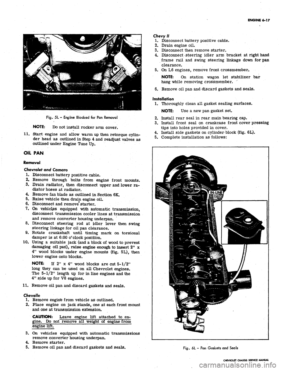
Fig.
5L
-
Engine Blocked for Pan Removal
NOTE: Do not install rocker arm cover.
11.
Start engine and allow warm up then retorque cylin-
der head
as
outlined in Step 4 and readjust valves as
outlined under Engine Tune Up.
OIL PAN
Removal
Chevrolet
and Camaro
1.
Disconnect battery positive cable.
2.
Remove through bolts from engine front mounts.
3.
Drain radiator, then disconnect upper and lower ra-
diator hoses at radiator.
4.
Remove fan blade as outlined in Section 6K.
5.
Raise vehicle then drain engine oil.
6. Disconnect and remove* starter.
7.
On
vehicles equipped with automatic transmission,
disconnect transmission cooler lines at transmission
and remove converter housing underpan.
8. Disconnect steering
rod at
idler lever then swing
steering linkage for oil pan clearance.
9. Rotate crankshaft until timing mark
on
torsional
damper is at 6:00 o'clock position.
10.
Using
a
suitable jack (and a block of wood to prevent
damaging oil pan), raise engine enough to insert 2"
x
4"
wood blocks under engine mounts (fig. 5L), then
lower engine onto blocks.
NOTE:
If
2"
x
4" wood blocks are cut 5-1/2"
long they can be used on all Chevrolet engines.
The 5-1/2" length up for in line engines and the
4"
side up for V8 engines.
11.
Remove oil pan and discard gaskets and seals.
Cfievel/e
1.
Remove enginfe from vehicle as outlined.
2.
Place engine on jack stands, one at each front mount
and one at transmission extension.
CAUTION: Leave engine lift attached
to
en-
gine.
Do not remove all weight
of
engine from
engine lift.
3.
On
vehicles equipped with automatic transmissions
remove converter housing underpan.
4.
Remove starter.
5.
Remove oil pan and discard gaskets and seals.
Chevy//
1.
Disconnect battery positive cable.
2.
Drain engine oil.
3.
Disconnect then remove starter.
4.
Disconnect-steering idler arm bracket at right hand
frame rail and swing steering linkage down for pan
clearance.
5.
On L6 engines, remove front crossmember.
NOTE:
On
station wagon
let
stabilizer
bar
hang while removing crossmember.
"
6. Remove oil pan and discard gaskets and seals.
Installation
1.
Thoroughly clean all gasket sealing surfaces.
NOTE: Use
a
new pan gasket set.
2.
Install rear seal in rear main bearing cap.
3.
Install front Seal on crankcase front cover pressing
tips into holes provided in cover.
4.
Install side gaskets on cylinder block (fig. 6L).
5.
Complete installation as follows:
Life
1
i
If ^
jfp^;.^3p
>\~^^ \s3^^r' -'••'•'-^^Hll
|^=-5p|:*iil^
mm
Fig.
6L
-
Pan Gaskets and Seals
CHEVROLET CHASSIS SERVICE MANUAL
Page 283 of 659
ENGINE 6-18
NOTE:
Bolts into crankcase cover should be
installed last. They are installed at an angle
and holes line up after rest of pan bolts are
snugged up.
Chevrolet and Camaro
a. If crankshaft was rotated while pan was off, place
timing mark at 6:00 o'clock position.
b.
Install oil pan and torque bolts to specifications.
c. Using a suitable jack (and a block of wood to prevent
damaging oil pan) raise engine enough to remove 2" x
4"
wood blocks, then lower engine.
d. On vehicles equipped with automatic transmission
install converter housing underpan, then connect
transmission cooler lines.
e. Install and connect starter.
f. Lower vehicle and install fan blades as outlined in
Section 6K.
g. Connect upper and lower radiator hoses.
h. Install through bolts in engine front mounts.
i. Connect battery positive cable.
j.
Fill radiator with coolant and fill engine with oil,
then start engine and check for leaks.
Chevelie
* a. Install oil pan and torque bolts to specifications.
b.
On vehicles equipped with automatic transmission,
install converter housing underpan.
c. Install starter.
d. Install engine as outlined.
Chevy II
a. Install oil pan and torque bolts to specifications.
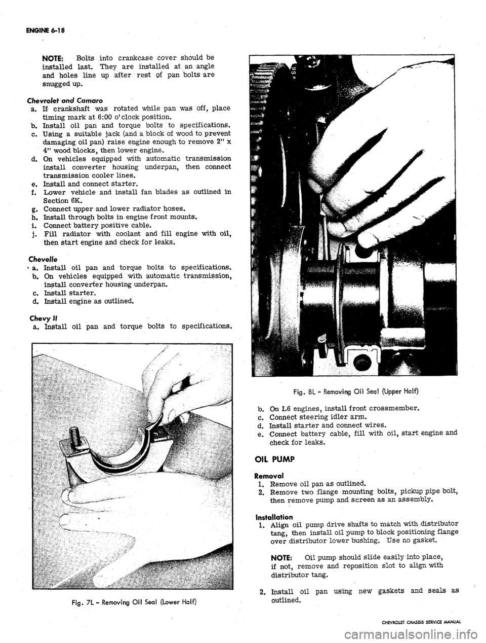
Fig.
7L- Removing Oil Sea! (Lower Half)
Fig.
8L - Removing Oil Seal (Upper Half)
b.
On L6 engines, install front crossmember.
c. Connect steering idler arm.
d. Install starter and connect wires.
e. Connect battery cable, fill with oil, start engine and
check for leaks.
OIL PUMP
Removal
1.
Remove oil pan as outlined.
2.
Remove two flange mounting bolts, pickup pipe bolt,
then remove pump and screen as an assembly.
Installation
1.
Align oil pump drive shafts to match with distributor
tang, then install oil pump to block positioning flange
over distributor lower bushing. Use no gasket.
NOTE:
Oil pump should slide easily into place,
if not, remove and reposition slot to align with
distributor tang.
2.
Install oil pan using new gaskets and seals as
outlined.
CHEVROLET CHASSIS SERVICE MANUAL
Page 290 of 659
ENGINE 6-25
refer to Section 6 of the Chassis Overhaul Manual.
Because of the interchangeability and similarity of
many engines, engine sub-assemblies and engine parts,
regardless of which passenger vehicle they are used in,
typical illustrations and procedures are used except
where specific illustrations or procedures are necessary
to clarify the operation. Although illustrations showing
bench operations are used, most single operations, when
not part of a general overhaul, should be performed (if
practical) with the engine in the vehicle.
COMPONENT REPLACEMENT AND ADJUSTMENT
ENGINE ASSEMBLY
Removal
• .1. Drain cooling system and engine oil.
2.
Remove air cleaner and disconnect battery cables at
battery.
3.
Remove hood as outlined in Section 11.
4.
Remove radiator and shroud as outlined in Sec-
tion 13.
5. Remove fan blade and pulley as outlined in Sec-
tion 6K.
6. Disconnect wires at:
• Starter solenoid
• Delcotron
• Temperature switch
• Oil pressure switch
• Coil
7. Disconnect:
• Accelerator linkage at pedal lever.
• Exhaust pipes at manifold flanges.
• Vacuum line to power brake unit at manifold (if
so equipped),
• Power steering pump lines at pump end (if so
equipped).
• Fuel line (from tank) at fuel pump.
• Engine cooler lines (if so equipped).
• Oil pressure gauge line (if so equipped).
8. Raise vehicle and place on jack stands.
9. Remove propeller shaft.
NOTE:
If plug for propeller shaft opening
in transmission is not available, drain
transmission.
10.
Disconnect:
• Shift linkage at transmission.
• Speedometer cable at transmission.
• Transmission cooler lines (if so equipped).
11.
On synchromesh equipped vehicles, disconnect clutch
linkage at cross-shaft then remove cross-shaft en-
gine bracket.
12.
Remove rocker arm covers as outlined, then attach
engine lifting adapter at the proper cylinder head bolt
locations.
13.
Remove front mount bolts.
14.
Attach lifting device and raise engine to take weight
off front mounts, then remove rear mount bolts.
15.
Raise engine to take weight off rear mount, then re-
move crossmember.
NOTE:
On Chevrolets it will be necessary to
remove mount from transmission before cross-
member can be removed.
16.
Remove engine-transmission assembly from vehicle
as a unit.
17.
Remove transmission (and clutch):
Synchromesh Transmission
a. Remove clutch housing cover plate screws.
b.
Remove bolts attaching the clutch housing to en-
gine block then remove transmission and clutch
housing as a unit.
NOTE:
Support the transmission as the last
mounting bolt is removed, and as it is being
pulled away from the engine (to prevent damage
to clutch disc).
c. Remove starter and clutch housing rear cover
plate.
d. Loosen clutch mounting bolts a turn at a time (to
prevent distortion of clutch cover) until the spring
pressure is released. Remove all bolts, clutch
disc and pressure plate assembly.
Automatic
Transmission
a. Lower engine, secured by the hoist, and support
engine on blocks.
b.
Remove starter and converter housing underpan.
c. Remove flywheel-to-converter attaching bolts.
d. Support transmission on blocks.
e. Remove transmission-to-engine mounting bolts.
f. With the hoist attached, remove blocks from the
engine only and slowly guide the engine from the
transmission.
18.
Mount engine in stand.
Installation
1.
Attach lifting device to engine and remove engine
from engine stand.
2.
Install transmission (and clutch):
Synchromesh Transmission
a. Install the clutch on flywheel as outlined in Sec-
tion 7.
b.
Install clutch housing rear cover and starter.
c. Install transmission and clutch housing as out-
lined in Section 7.
d. Install clutch housing cover screws and tighten
securely.
Automatic
Transmissions
a. Position engine adjacent to the transmission and
align the converter with the flywheel.
b.
Bolt transmission to engine, then raise engine and
transmission assembly and install flywheel to
converter attaching bolts.
c. Install converter housing underpan and starter.
3.
Tilt and lower engine and transmission assembly into
the chassis as a unit, guiding engine to align front
mounts with frame supports.
4.
Install front mount bolts and torque to specifications.
5. Raise engine enough to install rear crossmember,
then install crossmember, install rear mount, lower
engine and torque rear mount to specifications.
CHEVROLET CHASSIS SERVICE MANUAL
Page 291 of 659
ENGINE 6-26
6. Remove lifting device and lifting adapter then install
rocker arm covers as outlined.
7.
On synchromesh equipped vehicles, install clutch
cross-shaft engine bracket, then adjust and connect
clutch as outlined in Section 7.
8. Connect:
• Speedometer cable.
• Shift linkage at transmission.
• Transmission cooler lines (if so equipped).
9. Install propeller shaft.
10.
Remove jack stands and lower vehicle.
11.
Connect: \ '
Power steering pump lines (if so equipped).
Vacuum line to power brake unit (if so equipped).
Exhaust pipes at manifold flanges.
Accelerator linkage at pedal lever.
Fuel line at fuel pump.
Engine cooler lines (if so equipped).
Oil pressure gauge lines (if so equipped).
12.
Connect wires at:
Coil
Oil pressure switch
Temperature switch
Delcotron
Starter solenoid
13.
Install pulley, fan blade and fan belt as outlined in
Section 6K.
14.
Install radiator and shroud as outlined in Section 13.
15.
Install and adjust hood as outlined in Section 11.
16.
Connect battery cables.
17.
Fill with coolant, engine oil and transmission oil,
then start engine and check for leaks.
18.
Perform necessary adjustments and install air
cleaner.
INTAKE MANIFOLD
Removal
1.
Drain radiator and remove air cleaner.
2.
Disconnect:
Battery cables at battery.
Upper radiator and heater hose at manifold.
Accelerator linkage at pedal lever.
Fuel line at carburetor. ;
Wires at temperature sending switch and coil
(both sides).
Power brake hose at carburetor base.
Spark advance hose at distributor.
Crankcase ventilation hoses (as required).
3.
Remove distributor cap and mark rotor position with
chalk. Remove distributor clamp and distributor,
then position distributor cap rearward clear of
manifold.
4.
Remove coil.
5.
Remove manifold-to-head attaching bolts, then re^
move manifold, (with carburetor on) from engine and
discard gaskets and seals.
6. If manifold is to be replaced,,transfer:
Carburetor and carburetor mounting studs.
Temperature sending switch.
Water outlet and thermostat (use new gasket).
Heater hose adapter.
Choke coil.
Installation
1.
Clean gasket and seal surfaces of manifold, cylinder
heads and block.
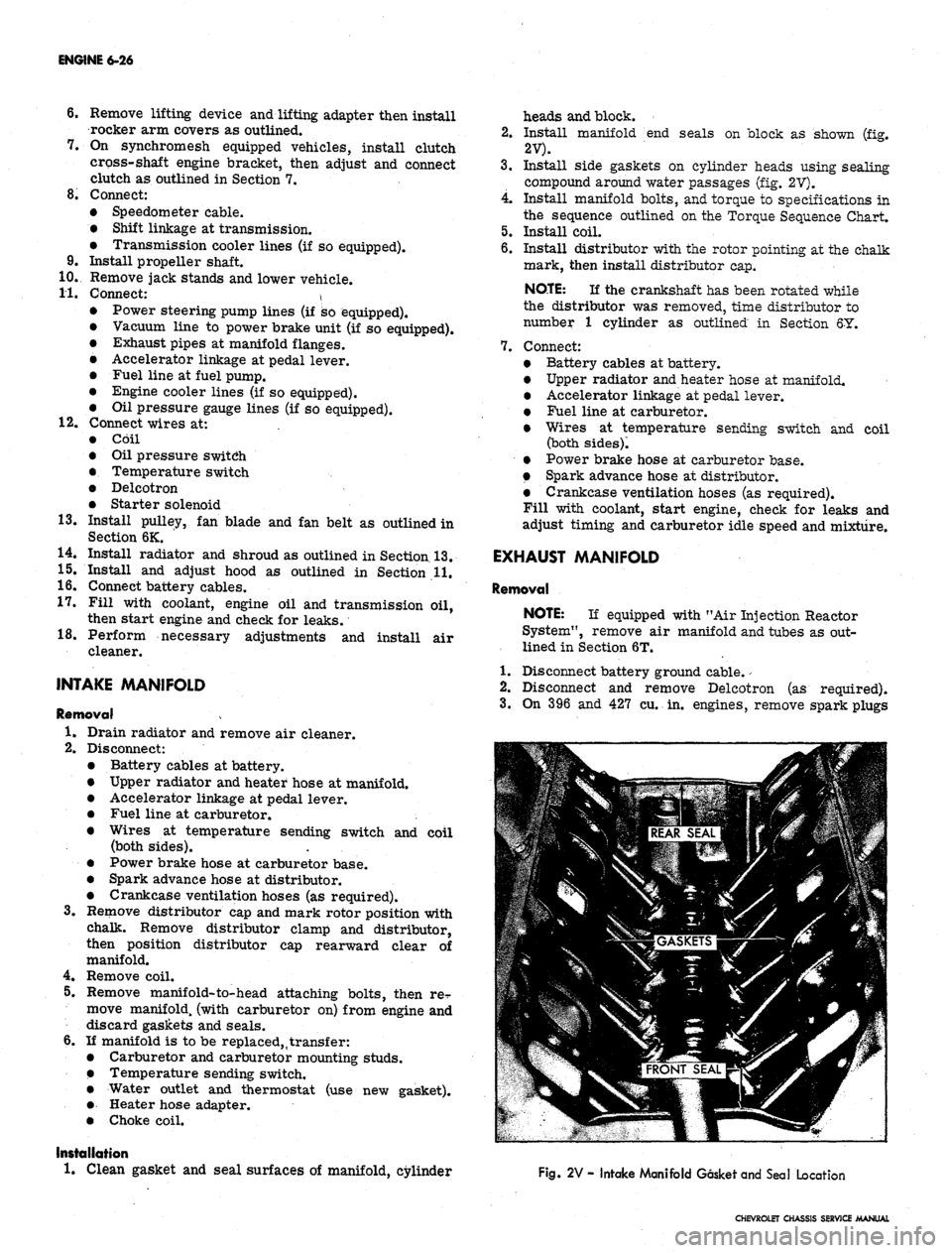
2.
Install manifold end seals on block as shown (fig.
2V).
3.
Install side gaskets on cylinder heads using sealing
compound around water passages (fig. 2V).
4.
Install manifold bolts, and torque to specifications in
the sequence outlined on the Torque Sequence Chart.
5.
Install coil.
6. Install distributor with the rotor pointing at the chalk
mark, then install distributor cap.
NOTE:
If the crankshaft has been rotated while
the distributor was removed, time distributor to
number 1 cylinder as outlined in Section 6Y.
7.
Connect:
Battery cables at battery.
Upper radiator and heater hose at manifold.
Accelerator linkage at pedal lever.
Fuel line at carburetor.
Wires at temperature sending switch and coil
(both sides)!
Power brake hose at carburetor base.
Spark advance hose at distributor.
Crankcase ventilation hoses (as required).
Fill with coolant, start engine, check for leaks and
adjust timing and carburetor idle speed and mixture.
EXHAUST MANIFOLD
Removal
NOTE:
If equipped with "Air Injection Reactor
System", remove air manifold and tubes as out-
lined in Section 6T.
1.
Disconnect battery ground cable.
-
2.
Disconnect and remove Delcotron (as required).
3.
On 396 and 427 cu. in. engines, remove spark plugs
Fig. 2V - Intake Manifold Gasket and Seal Location
CHEVROLET CHASSIS SERVICE MANUAL
Page 295 of 659
ENGINE 6-30
c". Install the valve locks and release the compres-
sor tool making sure the locks seat properly in
the upper groove of the valve stem.
NOTE: Grease may be used to hold the locks
in place while releasing the compressor tool.
396 and 427
cu.
in.
Engines
a. Install new valve stem oil seal (coated with oil)
in position over valve guide.
b.
Set the valve spring and damper and valve cap in
place.
c. Compress the spring with Tool J-5892 and install
the valve locks, then release the compressor tool,
making sure the locks seat properly in the groove
of the valve stem.
NOTE: Grease may be used to hold the locks
in place while releasing the compressor tool.
7.
Install spark ,plug, using a new gasket, and torque to
specifications. -
8. Install and adjust valve mechanism as outlined.
CYLINDER HEAD ASSEMBLY
Removal
1.
Remove intake manifold as outlined.
2.
Remove exhaust manifolds as outlined.
3.
Remove valve mechanism as outlined.
4.
Drain cooling system (block).
5.
Remove cylinder head bolts, cylinder head and gas-
ket. Place cylinder head on two blocks of wood to
prevent damage.
Installation
CAUTION: The gasket surfaces on both the
head and the block must be clean of any foreign
ttter and free of nicks or heavy scratches.
Under bolt threads in the block and threads on
Pie cylinder head bolt must be cleaned. (Dirt
will affect bolt torqueT)
1.
On engines using a STEEL gasket, coat both sides of
a new gasket with a good sealer, spread the sealer
thin and even. One method of applying the sealer that
will assure the proper- coat is with the use of a paint
roller. Too much sealer may hold the beads of the
gasket away from the head or block.
CAUTION: Use no sealer on engines using a
composition STEEL ASBESTOS gasket.
2.
Place the gasket in position over the dowel pins with
the bead up.
3.
Carefully guide cylinder head into place over dowel
pins and gasket.
4.
Coat threads of cylinder head bolts with sealing
compound and install finger tight.
5.
Tighten cylinder head bolts a little at a time in the
sequence shown on the torque sequence chart until
the specified torque is reached.
6. Install the exhaust manifold as outlined.
7.
Install the intake manifold as outlined.
8. Install and adjust the valve mechanism as outlined.
OIL
PAN
Removal
Chevrolet
and Camaro
1.
Disconnect battery positive cable.
2.
Disconnect distributor cap from distributor (to pr-e-
vent breaking distributor cap when engine is raised).
3.
Drain radiator, then disconnect lower radiator hose
at water pump and remove oil dip stick and tube
(where necessary). '
4.
Remove fan blade.
5.
Raise vehicle then drain engine oil;
6. Remove through bolts from engine front mounts.
Disconnect and remove starter.
7.
On vehicles equipped with automatic transmissions,
remove converter housing underpan.
8. Disconnect steering rod at idler lever then swing
steering linkage 4pwn for oil pan clearance.
9. Rotate crankshaft untii timing mark on torsional
damper is at 6:00 o'clock position.
10.
Using a suitable jack, and a block of wood to prevent
damaging oil pan, raise engine "enough to insert 2" x
4"
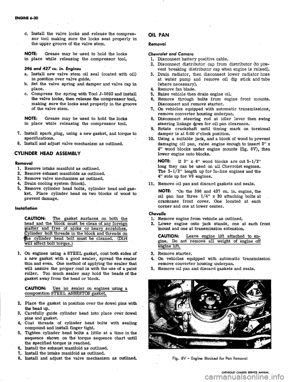
wood blocks under engine mounts (fig. 8V), then
lower engine onto blocks.
NOTE: If 2" x 4" wood blocks are cut 5-1/2"
long they can be used on all Chevrolet engines.
The 5-1/2" length up for In-line engines and the
4"
side up for V8 engines.
11.
Remove oil pan and discard gaskets and seals.
NOTE: -On the 396 and 427 cu. in. engine, the
oil pan has three 1/4" x 20 attaching bolts at ,
crankcase front cover. One located at each
corner and one at lower center.
Chevelle
1.
Remove engine from vehicle as outlined.
2.
Lower engine onto jack stands, one at each front
Tnaount and one at transmission extension.
CAUTION: Leave engine lift attached to en-
gine.
Do not remove all weight of engine off
engine lifET
3.
Remove starter.
4.
On vehicles equipped with automatic transmission
remove converter housing underpan.
5.
Remove oil pan and discard gaskets and seals.
Fig.
8V - Engine Blocked for Pan Removal
CHEVROLET CHASSIS SERVICE MANUAL