transmission oil CHEVROLET CAMARO 1967 1.G Chassis Owner's Manual
[x] Cancel search | Manufacturer: CHEVROLET, Model Year: 1967, Model line: CAMARO, Model: CHEVROLET CAMARO 1967 1.GPages: 659, PDF Size: 114.24 MB
Page 296 of 659
ENGINE 6-31
Chevy II
1.
Disconnect battery positive cable.
2.
Drain engine oil.
3.
Disconnect and remove starter.
4 Disconnect steering idler arm bracket at right hand
frame rail and swing steering linkage down for pan
clearance.
5.
Disconnect* exhaust pipes at manifolds and allow
pipes to hang free.
6. Remove oil pan and discard gaskets and seals.
Corvette
1.
Disconnect battery positive cable then remove oil
dipstick and tube.
2.
Raise and support vehicle then drain engine oil.
3.
Remove starter and flywheel underpan.
4.
Disconnect steering linkage idler at frame and lower
the linkage.
5.
Remove oil pan and discard gaskets and seals.
6. On Hi-Performance engines, the oil baffle must
be removed before additional operations can be
performed.
NOTE: On the 427 cu. in. engine, the oil pan
has three 1/4" x 20 attaching bolts at crankcase
front cqver. One located at each corner and one
at lower center.
Installation
1.
Thoroughly clean all gasket sealing surfaces.
NOTE: Use a new pan. gasket set.
2.
Install side gaskets on pan rails, using.gasket sealer
as a retainer.
3.
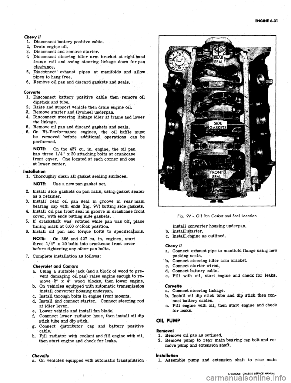
Install rear oil pan seal in groove in rear main
bearing cap with ends (fig. 9V) butting side gaskets.
4.
Install oil pan front seal in groove in .crankcaee front
cover, with ends butting side gaskets.
5.
If crankshaft was rotated while £>an was off, place
timing mark at 6:00 o'clock position.
6. Install oil pan and torque bolts to specifications.
NOTE: On 396 and 427 cu. in. engines, start
three 1/4" x 20 bolts into crankcase front cover
before tightening, any other pan bolts.
7.
Complete installation as follows:
Chevrolet
and Camaro
a. Using a suitable jack (and a block of wood to pre-
vent damaging oil pan) raise engine enough to re-
move 2" x 4" wood blocks, then lower engine.
b.
On vehicles equipped with automatic transmission
install converter housing underpan.
c. Install through bolts in engine front mounts.
d. Install and connect starter. Connect steering rod
at idler lever.
e. Lower vehicle and install fan blade.
f. Cbnnnect lower radiator hose, then install oil dip
stick tube and dip stick.
g. Connect distributor cap and battery positive
cable.
h. Fill radiator with coolant and fill engine with oil,
then start engine and check for leaks.
Chevelle
a. On vehicles equipped with automatic transmission
Fig.
9V - Oil Pan Gasket and Seal Location
install converter housing underpan.
b.
.Install starter.
c. Install, engine as outlined.
Chevy II
a. Connect exhaust pipe to manifold flange using new
packing seals.
b.
Connect steering idler arm bracket.
c. Connect starter wires..
d. Connect battery cable.
e. Fill with oil, start engine and check for leaks.
Corvette
a. Connect steering linkage.
b.
Install oil dip stick tube and dip stick then con-
nect battery cables.
c. Fill engine with oil, then start engine and check
for leaks.
OIL PUMP
Removal
1.
Remove oil pan as outlined.
2.
Remove pump to rear main bearing cap bolt and re-
move pump and extension shaft.
Installation
1.
Assemble pump and extension shaft to rear main
CHEVROLET CHASSIS SERVICE MANUAL
Page 302 of 659
ENGINE 6-37
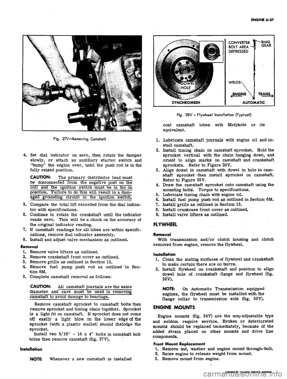
Fig.
27V—Removing Camshaft
4.
Set dial indicator on zero, then rotate the damper
slowly, or attach an auxiliary starter switch and
"bump" the engine over, until the push rod is in the
fully raised position.
CAUTION: The primary distributor lead must
be disconnected from the negative post on the
coil and the ignition switch must be in the on
position. Failure to do this will result in a dam-
aged grounding circuit in the ignition switch.
5.
Compare the total lift recorded from the dial indica-
tor with specifications.
6. Continue to rotate the crankshaft until the indicator
reads zero. This will be a check on the accuracy of
the original indicator reading.
7.
If camshaft readings for all lobes are within specifi-
cations, remove dial indicator assembly.
8. Install and adjust valve mechanism as outlined.
Removal
1.
Remove valve lifters as outlined.
2.
Remove crankshaft front cover as outlined.
3.
Remove grille as outlined in Section 13.
4.
Remove fuel pump push rod as outlined * in Sec-
tion 6M.
5.
Complete camshaft removal as follows:
CAUTION: All camshaft journals are the same
diameter and care must be used in removing
camshaft to avoid damage to bearings.
Remove camshaft sprocket to camshaft bolts then
remove sprocket and timing chain together. Sprocket
is a light fit on camshaft. If sprocket does not come
off easily a light blow on the lower edge of the
sprocket (with a plastic mallet) should dislodge the
sprocket.
Install two 5/16" - 18 x 4" bolts in camshaft bolt
holes then remove camshaft (fig. 27V).
Installation
NOTE: Whenever a new camshaft is installed
CONVERTER
BOLT AREA -
DEPRESSED
SYNCHROMESH
RING
GEAR
TRANS.,
AUTOMATIC
Fig.
28V - Flywheel Installation (Typical)
coat camshaft lobes with Molykote or its
equivalent.
1.
Lubricate camshaft journals with engine oil and in-
stall camshaft.
2.
Install timing chain on camshaft sprocket. Hold the
sprocket vertical with the chain hanging down, and
orient to align marks on camshaft and crankshaft
sprockets. Refer to Figure 20V.
3.
Align dowel in camshaft with dowel in hole in cam-
shaft sprocket then install sprocket on camshaft.
Refer to Figure 25V.
4.
Draw the camshaft sprocket onto camshaft using the
mounting bolts. Torque to specifications.
5.
Lubricate timing chain with engine oil.
6. Install fuel pump push rod as outlined in Section 6M.
7.
Install grille as outlined in Section 13.
8. Install crankcase front cover as outlined.
9. Install valve lifters as outlined.
FLYWHEEL
Removal
With transmission and/or clutch housing and clutch
removed from engine, remove the flywheel.
Installation
1.
Clean the mating surfaces of flywheel and crankshaft
to make certain there are no burrs.
2.
Install flywheel on crankshaft and position to align
dowel hole of crankshaft flange and flywheel (fig.
28V).
NOTE: On Automatic Transmission equipped
engines, the flywheel must be installed with the
flange collar to transmission side (fig. 33V).
ENGINE MOUNTS
Engine mounts (fig. 34V) are the nonr adjustable type
and seldom require service. Broken or deteriorated
mounts should be replaced immediately, because of the
added strain placed on other mounts and drive line
components.
Front Mount Replacement
1.
Remove nut, washer and engine mount through-bolt.
2.
Raise engine to release weight from mount.
3.
Remove mount from engine.
CHEVROLET CHASSIS SERVICE MANUAL
Page 309 of 659

SECTION 6M
ENGINE FUEL
CONTENTS OF THIS SECTION
Page
Carburetors 6M-1 Fuel Pumps .
Air Cleaners 6M-7 Special Tools
Page
6M-10
6M-12
CARBURETORS
INDEX
Page
General Description 6M-1
Service Procedures 6M-1
Preliminary Checks 6M-1
Idle Speed and Mixture Adjustment ........... 6M-1
Fast Idle Adjustment .................. 6M-3
Choke Adjustment 6M-3
Float Adjustment 6M-4
Page
Additional Adjustments 6M-4
Removal 6M-4
Test Before Installation 6M-5
Installation 6M-5
Fuel Filter Maintenance 6M-5
Choke Coil Replacement 6M-5
Throttle Linkage Adjustment . . 6M-6
GENERAL DESCRIPTION
Various carburetors (fig. lc) are used with Chevrolet,
Chevelle, Chevy II, Camaro and Corvette passenger
vehicles. These carburetors are designed to meet the
particular requirements of engines, transmissions and
vehicles, therefore carburetors that look alike are not
always interchangeable. (Refer to carburetor part num-
ber and/or specifications.)
Because many service procedures for the various
carburetors are similar, typical illustrations and pro-
cedures are used except where specific illustrations or
procedures are necessary to clarify the operation.
This section covers removal, installation and adjust-
ments (on engine) of carburetors. Also covered in this
section are maintenance procedures for choke coils,
throttle linkage and fuel filters. For carburetor .over-
haul procedures and additional adjustments (bench), re-
fer to Section 6M of the Overhaul Manual under the
carburetor being serviced.
Specifications for carburetors are located in the back
of this manual.
SERVICE PROCEDURES
Preliminary Checks
1.
Thoroughly warm-up engine. If the engine is cold,
allow to run for at least 15 minutes.
2.
Inspect torque of carburetor to intake manifold bolts
and intake manifold to cylinder head bolts to exclude
the possibility of air leaks.
3.
Inspect manifold heat control valve (if used) for free-
dom of action and correct spring tension.
Idle Speed and Mixture Adjustment (Except Air Injection
Reactor System)
NOTE:
This adjustment should be performed
with engine at operating temperature and park-
ing brake applied.
1.
Remove Air Cleaner.
2.
Connect tachometer and vacuum gauge to engine, then
set hand brake and shift transmission into neutral.
3.
As a preliminary adjustment, turn idle mixture
screws lightly to seat and back out 1-1/2 turns.
CAUTION: Do not turn idle mixture screw
tightly against seat or damage may result.
4.
With engine running (choke wide open) adjust idle
speed screw to specified idle speed, (automatic
transmission in drive, synchronized transmission in
neutral).
5. Adjust idle mixture screw to obtain highest steady
vacuum at specified idle speed.
NOTE:
On air conditioned vehicles, turn air
conditioning to the "on" position and hold the
hot idle compensator valve closed while adjust-
ing idle speed and idle mixture screws.
NOTE:
On Rochester BV carburetors the idle
mixture screw should be turned out 1/4 turn
from the "lean roll" position. The definition
of "lean roll" point is a 20 to 30 rpm drop
in engine speed obtained by leaning the idle
mixture.
6. Repeat Steps 4 and5 as needed for final adjustment.
NOTE:
If necessary, final adjustment of the \
carburetor may be made with the air cleaner
installed.
7. Turn engine off, remove gauges and install air
clearer.
CHEVROLET CHASSIS SERVICE MANUAL
Page 313 of 659
ENGINE FUEL 6M-5
3.
Disconnect choke rod or choke cable.
4.
Disconnect accelerator linkage.
5.
If equipped with Automatic transmission, discon-
nect TV linkage.
6. Remove carburetor attaching nuts and/or bolts and
remove carburetor.
Test Before Installation -
It is good shop practice to fill the carburetor bowl
before installing the carburetor. This reduces the strain
on the starting motor and battery and reduces the pos-
sibility of backfiring while attempting to start the engine.
A fuel pump clamped to the bench, a small supply of fuel
and the necessary fittings enable the carburetor to be
filled1 and the operation of the float and'intake needle and
seat to be checked. Operate the throttle several times
and check the discharge from the pump jets before in-
stalling the carburetor.
Installation
1.
Be certain throttle body and intake manifold sealing
surfaces are clean.
2.
Install new carburetor to manifold flange gasket (if
required).
3.
Install carburetor over manifold studs.
4.
Start vacuum and fuel lines at carburetor.
5.
Install attaching nuts and/or bolts and tighten
securely.
6. Tighten fuel and vacuum lines.
7.
Connect and adjust accelerator and TV linkage.
8. Connect choke tube or choke rod.
9. Adjust idle speed and mixture, then install air
cleaner. #
Fuel Filter Maintenance
1.
Disconnect fuel line connection at inlet fuel filter
nut.
2.
Remove inlet fuel filter nut from carburetor with a
1"
box wrench or socket.
3.
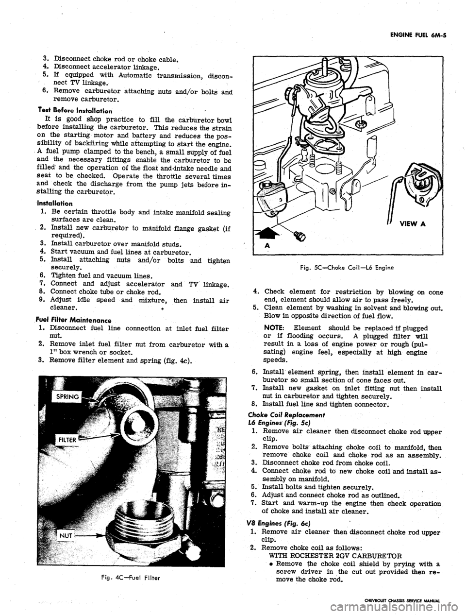
Remove filter element and spring (fig. 4c).
Fig. 5C-Choke Coil-L6 Engine
4.
Fig. 4C-Fuel Filter
Check element for restriction by blowing on cone
end, element should allow air to pass freely.
5.
Clean element by washing in solvent and blowing out.
Blow in opposite direction of fuel flow.
NOTE: Element should be replaced if plugged
or if flooding ocpurs. A plugged filter will
result in a loss of engine power or rough (pul-
sating) engine feel, especially at high engine
speeds.
6. Install element spring, then install element in car-
buretor so small section of cone faces out.
7.
Install new gasket on inlet fitting nut then install
nut in carburetor and tighten securely.
8. Install fuel line and tighten connector.
Choke Coil Replacement
L6 Engines (Fig. 5c)
1.
Remove air cleaner then disconnect choke rod upper
clip.
2.
Remove bolts attaching choke coil to manifold, then
remove choke coil and choke rod as an assembly.
3.
Disconnect choke rod from choke coil.
4.
Connect choke rod to new choke coil and install as-
sembly on manifold.
5.
Install bolts and tighten securely.
6. Adjust and connect choke rod as outlined.
7.
Start and warm-up the engine then check operation
of choke and install air cleaner.
V8 Engines (Fig. 6c)
1.
Remove air cleaner then disconnect choke rod upper
clip.
2.
Remove choke coil as follows:
WITH ROCHESTER 2GV CARBURETOR
• Remove the choke coil shield by prying with a
screw driver in the cut out provided then re-
move the choke rod.
CHEVROLET CHASSIS SERVICE MANUAL
Page 314 of 659
ENGINE FUEL 6M-6
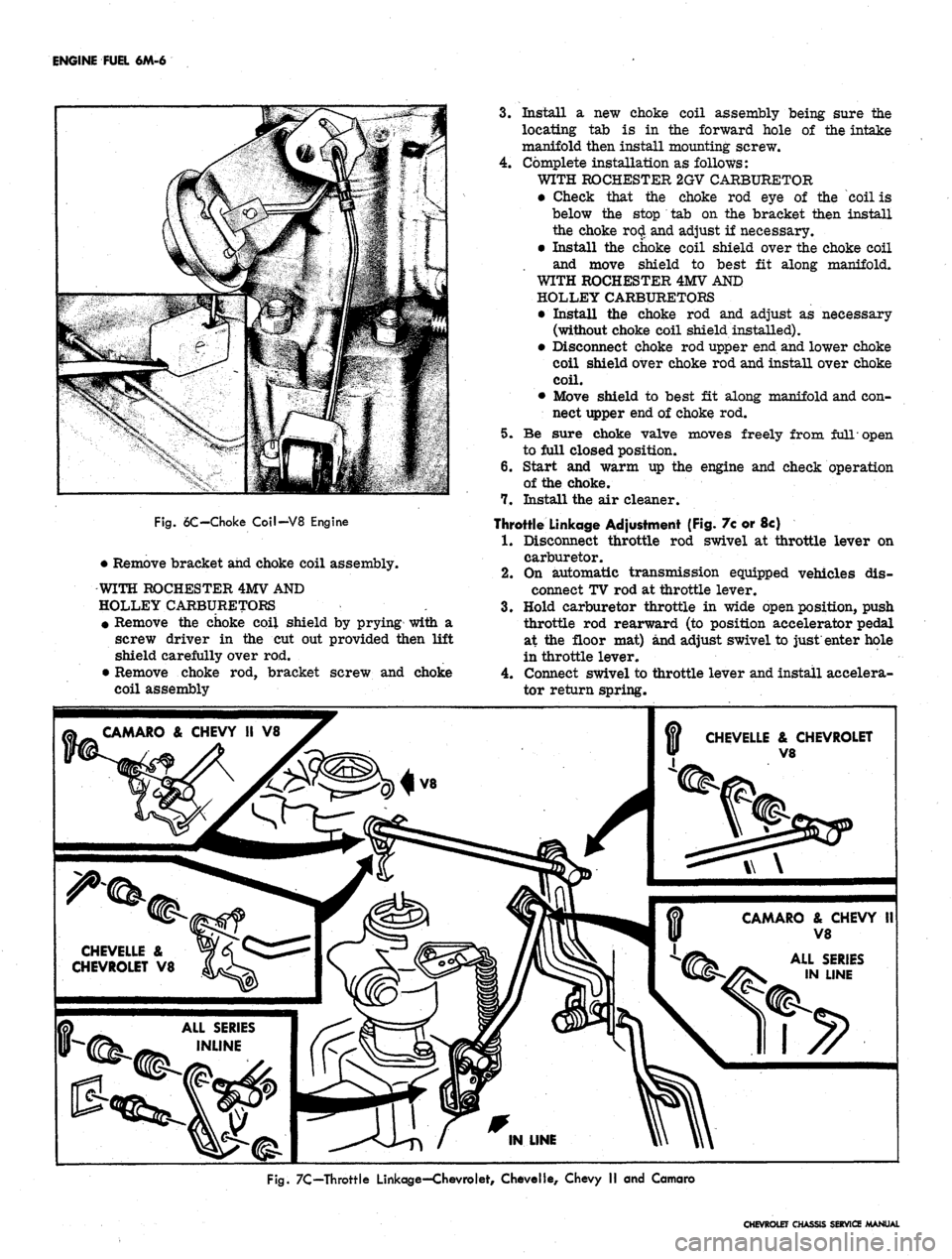
Fig.
6C-Choke Coil-V8 Engine
• Remove bracket and choke coil assembly.
WITH ROCHESTER 4MV AND
HOLLEY CARBURETORS
• Remove the choke coil shield by prying with a
screw driver in the cut out provided then lift
shield carefully over rod.
• Remove choke rod, bracket screw and choke
coil assembly
3.
Install a new choke coil assembly being sure the
locating tab is in the forward hole of the intake
manifold then install mounting screw.
4.
Complete installation as follows:
WITH ROCHESTER 2GV CARBURETOR
• Check that the choke rod eye of the coil is
below the stop tab on the bracket then install
the choke
ro
• Install the choke coil shield over the choke coil
and move shield to best fit along manifold.
WITH ROCHESTER 4MV AND
HOLLEY CARBURETORS
• Install the choke rod and adjust as necessary
(without choke coil shield installed).
• Disconnect choke rod upper end and lower choke
coil shield over choke rod and install over choke
coil.
• Move shield to best fit along manifold and con-
nect upper end of choke rod.
5. Be sure choke valve moves freely from full open
to full closed position.
6. Start and warm up the engine and check operation
of the choke.
7. Install the air cleaner.
Throttle Linkage Adjustment (Fig. 7c or 8c)
1.
Disconnect throttle rod swivel at throttle lever on
carburetor.
2.
On automatic transmission equipped vehicles dis-
connect TV rod at throttle lever.
3.
Hold carburetor throttle in wide open position, push
throttle rod rearward (to position accelerator pedal
at the floor mat) and adjust swivel to just enter hole
in throttle lever.
4.
Connect swivel to throttle lever and install accelera-
tor return spring.
CAMARO & CHEVY II V8
CHEVELLE & CHEVROLET
V8
CAMARO
&
CHEVY
II
V8
CHEVELLE &
CHEVROLET V8
ALL SERIES
IN LINE
ALL SERIES
INLINE
Fig.
7C—Throttle Linkage—Chevrolet, Chevelle, Chevy II and Camaro
CHEVROLET CHASSIS SERVICE MANUAL
Page 315 of 659
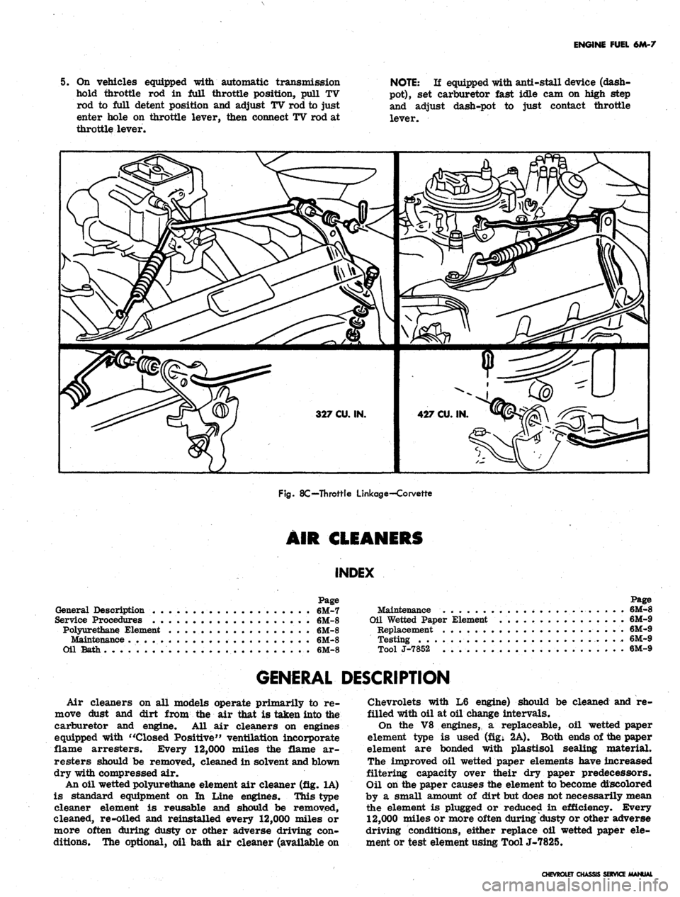
ENGINE FUEL 6M-7
5. On vehicles equipped with automatic transmission
hold throttle rod in full throttle position, pull TV
rod to full detent position and adjust TV rod to just
enter hole on throttle lever, then connect TV rod at
throttle lever.
NOTE:
If equipped with anti-stall device (dash-
pot),
set carburetor fast idle cam on high step
and adjust dash-pot to just contact throttle
lever.
327
CU.
IN.
427
CU.
IN.
Fig.
8C—Throttle Linkage-Corvette
AIR
CLEANERS
INDEX
Page
General Description 6M-7
Service Procedures . . 6M-8
Polyurethane. Element 6M-8
Maintenance 6M-8
Oil Bath 6M-8
Page
Maintenance
...........* 6M-8
Oil
Wetted
Paper
Element
6M-9
Replacement
* . 6M-9
Testing 6M-9
Tool J-7852 . 6M-9
GENERAL DESCRIPTION
Air cleaners on all models operate primarily to re-
move dust and dirt from the air that is taken into the
carburetor and engine. All air cleaners on engines
equipped with "Closed Positive" ventilation incorporate
flame arresters. Every 12,000 miles the flame ar-
resters should be removed, cleaned in solvent and blown
dry with compressed air.
An oil wetted polyurethane element air cleaner (fig. 1A)
is standard equipment on In Line engines. This type
cleaner element is reusable and should be removed,
cleaned, re-oiled and reinstalled every 12,000 miles or
more often during dusty or other adverse driving con-
ditions. The optional, oil bath air cleaner (available on
Chevrolets with L6 engine) should be cleaned and re-
filled with oil at oil change intervals.
On the V8 engines,, a replaceable, oil wetted paper
element type is used (fig; 2A). Both ends of me paper
element are bonded with plastisol sealing material.
The improved oil wetted paper elements have increased
filtering capacity over their dry paper predecessors.
Oil on the paper causes the element to become diBcolored
by a small amount of dirt but does not necessarily mean
the element is plugged or reduced in efficiency. Every
12,000 miles or more often during dusty or other adverse
driving conditions, either replace oil wetted paper ele-
ment or test element using ToolJ-7825.
CHEVROLET CHASSIS SOVICE/MANUAL
Page 363 of 659
CLUTCH AND TRANSMISSIONS 7-4
5.
Install Tool J-5824 to support the clutch assembly
during removal.
NOTE: Look for "X" mark on flywheel and on
clutch cover. If MX" mark is not evident, prick
punch marks on flywheel and clutch cover for
indexing purposes during installation.
6. Loosen the clutch-to-flywheel attaching bolts evenly
1 turn at a time until spring pressure is released,
then remove the bolts, and remove clutch assembly.
Installation to Vehicle
Clean pressure plate and flywheel face. (They should
be free of oil, grease, metal deposits or burned spots).
1.
Position the clutch disc and pressure plate in relar
tive installed position and support them with align-
ment Tool J-5824.
NOTE: The driven disc on the 4 and 6 cylinder
engines is installed with the damfper springs to
the flywheel side; the V-8 is opposite, however,
THE GREASE SLINGER IS ALWAYS ON THE
TRANSMISSION SIDE.
2.
Turn clutch assembly until "X" mark on cover lines
up with "X" mark oh flywheel, then align cover bolt
holes to nearest flywheel holes.
3.
Install a bolt in every hole and tighten down evenly
and gradually until tight (to avoid possible clutch
distortion).
NOTE: Cover loads are as high as 1-1/4 tons.
4.
Remove pilot tool.
5.
Unhook clutch fork and lubricate ball socket and fork
fingers at release bearing end with a high melting
point grease such as graphite and reinstall fork on
ball stud. On Corvette models use Moly Grease.
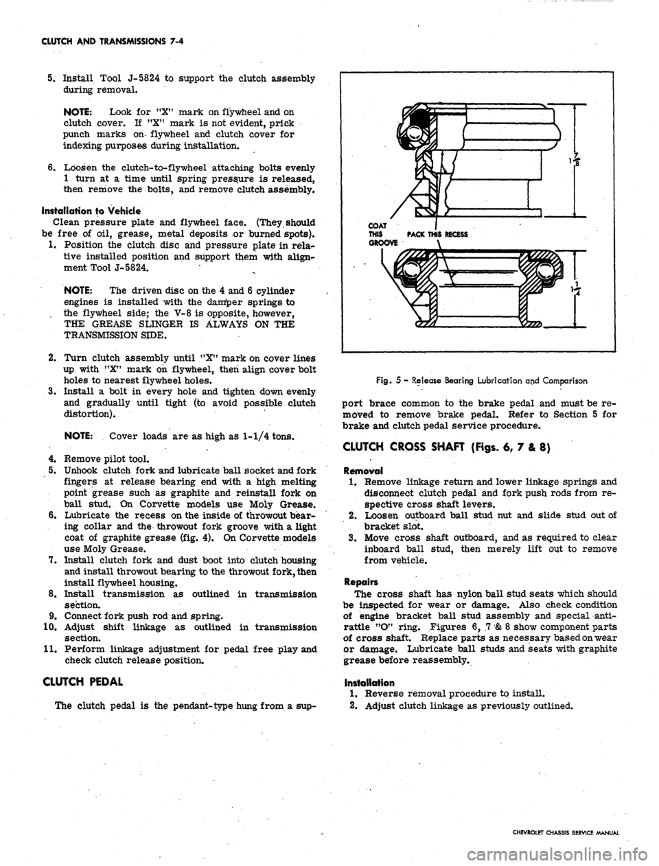
6. Lubricate the recess on the inside of throwout bear-
ing collar and the throwout fork groove with a light
coat of graphite grease (fig. 4). On Corvette models
use Moly Grease.
7.
Install clutch fork and dust boot into clutch housing
and install throwout bearing to the throwout fork, then
install flywheel housing.
8. Install transmission as outlined in transmission
section.
9. Connect fork push rod and spring.
10.
Adjust shift linkage as outlined in transmission
section.
11.
Perform linkage adjustment for pedal free play and
check clutch release position.
CLUTCH PEDAL
The clutch pedal is the pendant-type hung from a sup-
Fig. 5 - Release Bearing Lubrication and Comparison
port brace common to the brake pedal and must be re-
moved to remove brake pedal. Refer to Section 5 for
brake and clutch pedal service procedure.
CLUTCH CROSS SHAFT (Figs. 6, 7 & 8)
Removal
1.
Remove linkage return and lower linkage springs and
disconnect clutch pedal and fork push rods from re-
spective cross shaft levers.
2.
Loosen outboard ball stud nut and slide stud out of
bracket slot.
3.
Move cross shaft outboard, and as required to clear
inboard ball stud, then merely lift out to remove
from vehicle.
Repairs
The cross shaft has nylon ball stud seats which should
be inspected for wear or damage. Also check condition
of engine bracket ball stud assembly and special anti-
rattle "O" ring. Figures 6, .7
&
8 show component parts
of cross shaft. Replace parts as necessary based on wear
or damage. Lubricate ball studs and seats with graphite
grease before reassembly.
Installation
1.
Reverse removal procedure to install.
2.
Adjust clutch linkage as previously outlined.
CHEVROLET CHASSIS SERVICE MANUAL
Page 365 of 659

CLUTCH AND TRANSMISSIONS 7-6
L6 ENGINE
V8 ENGINE
Fig.
7 - Lower Linkage Details - Camaro
Fig.
8 - Corvette Lower Linkage Details
THREE-SPEED (SA6INAW FULLY SYNCHRONIZED)
TRANSMISSION
General Description . .
Maintenance and Adjustments
Shift Linkage Adjustment
Shift Control Lever
&
Bracket Assembly
Speedometer Driven Gear ..........
INDEX
Page Page
7-6 Extension Oil Seal Replacement 7-7
7-7 Transmission Side Cover 7-8
7-7 Component Part Replacement 7-8
7-7 Transmission Replacement (exc. Corvette) . 7-8
7-7 Corvette Transmission Replacement 7-9
GENERAL DESCRIPTION
The Saginaw three speed fully synchronized (all forward
gears) transmission incorporates helical drive gears
throughout.
The main drive gear is supported by a ball bearing at
the front end of the transmission case and is piloted at
its front end in an oil impregnated bushing mounted in the
engine crankshaft. The front end of the mainshaft is
piloted in a row of roller bearings set into the hollow end
of the main drive gear and the rear end is carried by a
ball bearing mounted in the front of the extension housing.
The countergear is carried on a single row of rollers at
both ends while thrust is taken on thrust washers located
between the ends of the gear and the thrust bosses in the
case.
Ah anti-rattle plate assembly at the front of the
countergear provides a constant spring tension between the
counter and clutch gears to reduce torsional vibrations.
The reverse idler gear is carried on a bushing finish
bored in place. It rotates on a short idler shaft with a
steel thrust washer tanged into the case against the rear
face. Forward movement is stopped by a snap ring on
the idler shaft.
Gear shifting is manual through shift control rods to
the rearward shift lever of the side cover assembly for
first and reverse gear; and through a cross shaft assem-
bly (Chevrolet models) attached to the forward side cover
lever for second and third gear. All three forward gears
are fully synchronized. The synchronizer assemblies
consist of a clutch hub, clutch sleeve, two clutch key
springs and three energizer clutch keys and are retained
as an assembly on the main shaft by a snap ring.
The transmission may be used as an aid in deceleration
by downshifting in sequence without double-clutching or
any gear clashing. Reverse is not- synchronized, how-
ever, it is a helical gear to insure quiet operation.
CHEVROLET CHASSIS SERVICE MANUAL
Page 366 of 659
CLUTCH AND TRANSMISSIONS 7-7
MAINTENANCE AND ADJUSTMENTS
CHEVROLET, CHEVELLE, CHEVY II, CAMARO,
SHIFT LINKAGE ADJUSTMENT
In cases where the gearshift linkage has been discon-
nected, it should be adjusted as follows:
1.
Move both transmission shift levers until transmis-
sion is in neutral. Neutral detents in transmission
cover must both be engaged to make this adjustment
correctly. (To check, start engine with clutch dis-
engaged, and release clutch slowly.)
2.
Move selector lever to neutral position. Align first
and reverse tube lever with the second and third
shifter tube lever on the mast jacket. This may be
done by having an assistant hold the mast .jacket shift
levers aligned in neutral position or use a simple
gauge or pin to align these levers in neutral.
3.
Make necessary adjustment to align shift control
rods and transmission levers in neutral position.
Move selector lever through all positions to check ad-
justment and to insure over-travel in all positions.
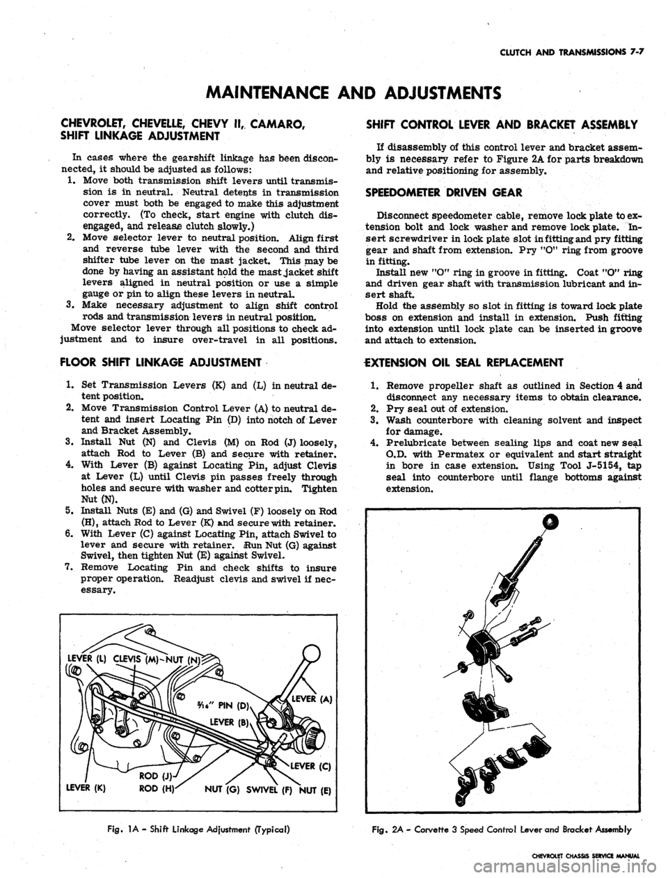
FLOOR SHIFT LINKAGE ADJUSTMENT
1.
Set Transmission Levers (K) and (L) in neutral de-
tent position.
2.
Move Transmission Control Lever (A) to neutral de-
tent and insert Locating Pin (D) into notch of Lever
and Bracket Assembly.
3.
Install Nut (N) and Clevis (M) on Rod (J) loosely,
attach Rod to Lever (B) and secure with retainer.
4.
With Lever (B) against Locating Pin, adjust Clevis
at Lever (L) until Clevis pin passes freely through
holes and secure with washer and cotter pin. Tighten
Nut (N).
5.
Install Nuts (E) and (G) and Swivel (F) loosely on Rod
(H),
attach Rod to Lever (K) and secure with retainer.
6. With Lever (C) against Locating Pin, attach Swivel to
lever and secure with retainer. iRun Nut (G) against
Swivel, then tighten Nut (E) against Swivel.
7.
Remove Locating Pin and check shifts to insure
proper operation. Readjust clevis and swivel if nec-
essary.
LEVER (A)
LEVER (L) CLEVIS (M)-NUT (N
LEVER (C)
ROD(J).
" - -
LEVER (K) ROD (H)^ NUT '(G) SWIVEL (F) ^NUT (E)
SHIFT CONTROL LEVER AND BRACKET ASSEMBLY
If disassembly of this control lever and bracket assem-
bly is necessary refer to Figure 2A for parts breakdown
and relative positioning for assembly.
SPEEDOMETER DRIVEN GEAR
Disconnect speedometer cable, remove lock plate to ex-
tension bolt and lock washer and remove lock plate. In-
sert screwdriver in lock plate slot in fitting and pry fitting
gear and shaft from extension. Pry "O" ring from groove
in fitting.
Install new "OM ring in groove in fitting. Coat "O" ring
and driven gear shaft with transmission lubricant and in-
sert shaft.
Hold the assembly so slot in fitting is toward lock plate
boss on extension and install in extension. Push fitting
into extension until lock plate can be inserted in groove
and attach to extension.
EXTENSION OIL SEAL REPLACEMENT
.1.
Remove propeller shaft as outlined in Section 4 and
disconnect any necessary items to obtain clearance.
2.
Pry seal out of extension.
3.
Wash counterbore with cleaning solvent and inspect
for damage.
4.
Prelubricate between sealing lips and coat new seal
O.D. with Permatex or equivalent and start straight
in bore in case extension. Using Tool J-5154, tap
seal into counterbore until flange bottoms against
extension.
Fig.
1A- Shift Linkage Adjustment (Typical)
Fig.
2A - Corvette 3 Speed Control Lever and Bracket Assembly
CHEVROLET CHASSIS SERVICE MANUAL
Page 367 of 659
CLUTCH AND TRANSMISSIONS 7-3
DETENT CAM
DETENT SPRING
DETENT CAM
2-3 SHIFT
FORK
DETENT CAM
PIVOT PIN
1ST & REV. 1ST& REV.
SHIFTER SHAFT SHIFT FORK
DETENT CAM
RETAINER RING
2-3 SHIFTER SHAFT
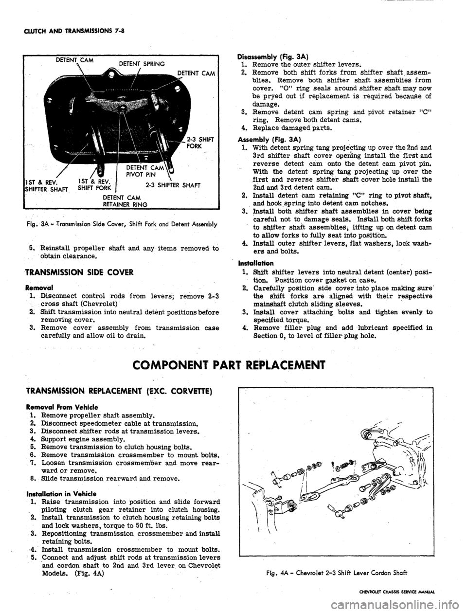
Fig. 3A
•*
Transmission Side Cover, Shift Fork and Detent Assembly
5. Reinstall propeller shaft and any items removed to
obtain clearance.
TRANSMISSION SIDE COVER
Removal •
1.
Disconnect control rods from levers; remove 2-3
cross shaft (Chevrolet)
2.
Shift transmission into neutral detent positions before
removing cover.
3.
Remove cover assembly from transmission case
carefully and allow oil to drain.
Disassembly (Fig. 3A)
1.
Remove the outer shifter levers.
2.
Remove both shift forks from shifter shaft assem-
blies.
Remove both shifter shaft assemblies from
cover. "OM ring seals around shifter shaft may now
be pryed out if replacement is required because of
damage.
3.
Remove detent cam spring and pivot retainer "C"
ring. Remove both detent cams.
4.
Replace damaged parts.
Assembly (Fig. 3A)
1.
With,
detent spring tang projecting up over the
2nd
and
3rd shifter shaft cover opening install the first and
reverse detent cam onto the detent cam pivot pin.
With the detent spring tang projecting up over the
first and reverse shifter shaft cover hole install the
2nd an£ 3rd detent cam.
2.
Install detent cam retaining "C" ring to pivot shaft,
and hook spring into detent cam notches.
3.
Install both shifter shaft assemblies in cover being
careful not to damage seals. Install both shift forks
to shifter shaft assemblies^ lifting up on detent cam
to allow forks to fully seat into position.
4.
Install outer shifter levers, flat washers, lock wash-
ers and bolts.
Installation
1.
Shift shifter levers into neutral detent (center) posi-
tion.
Position cover gasket on case.
2.
Carefully position side cover into place making sure'
the shift forks are aligned with their respective
mainshaft clutch sliding sleeves.
3.
Install cover attaching bolts and tighten evenly to
specified torque.
4.
Remove filler plug and add lubricant specified in
Section 0, to level of filler plug hole.
COMPONENT PART REPLACEMENT
TRANSMISSION REPLACEMENT (EXC. CORVETTE)
Removal From Vehicle
1.
Remove propeller shaft assembly.
2.
Disconnect speedometer cable at transmission.
3.
Disconnect shifter rods at transmission levers.
4.
Support engine assembly.
5. Remove transmission to clutch housing bolts.
6. Remove transmission crossmember to mount bolts.
7. Loosen transmission crossmember and move rear-
ward or remove.
8. Slide transmission rearward and remove.
Installation in Vehicle
1.
Raise transmission into position and slide forward
piloting clutch gear retainer into clutch housing.
2.
Install transmission to clutch housing retaining bolts
and lock washers, torque to 50 ft. lbs.
3.
Repositioning transmission crossmember and install
retaining bolts.
4.
Install transmission crossmember to mount bolts.
5. Connect and adjust shift rods at transmission levers
and cordon shaft to 2nd and 3rd lever on Chevrolet
Models. (Fig. 4A)
Fig. 4A - Chevrolet 2-3 Shift Lever Cordon Shaft
CHEVROLET CHASSIS SERVICE MANUAL