bulb CHEVROLET CAMARO 1967 1.G Chassis Owner's Manual
[x] Cancel search | Manufacturer: CHEVROLET, Model Year: 1967, Model line: CAMARO, Model: CHEVROLET CAMARO 1967 1.GPages: 659, PDF Size: 114.24 MB
Page 523 of 659
ELECTRICAL-BODY AND CHASSIS 12-11
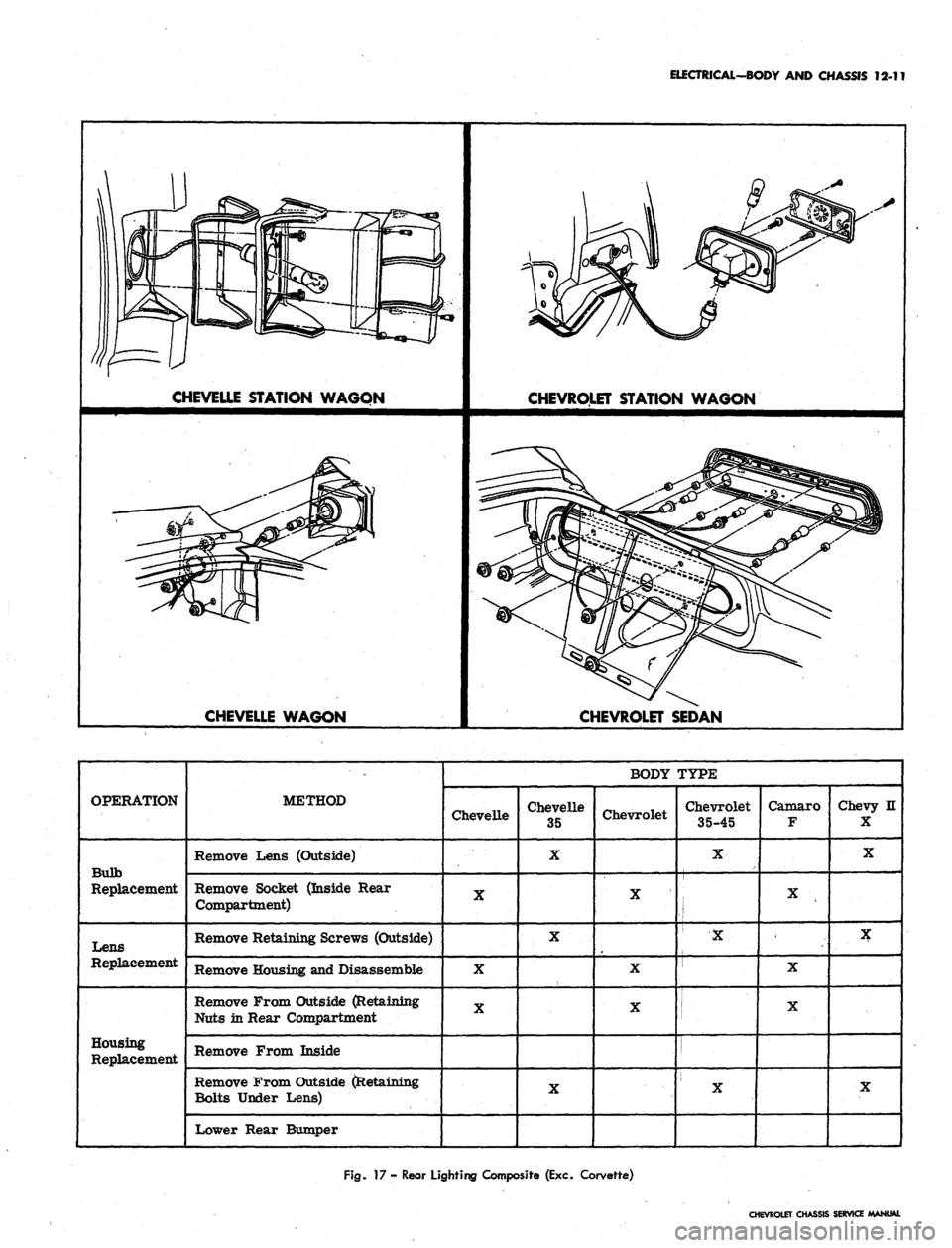
CHEVELLE STATION WAGON
CHEVROLET STATION WAGON
CHEVELLE WAGON
CHEVROLET SEDAN
OPERATION
Bulb
Replacement
Lens
Replacement
Housing
Replacement
METHOD
Remove Lens (Outside)
Remove Socket (Inside Rear
Compartment)
Remove Retaining Screws (Outside)
Remove Housing and Disassemble
Remove From Outside (Retaining
Nuts in Rear Compartment
Remove From Inside
Remove From Outside (Retaining
Bolts Under Lens)
Lower Rear Bumper
BODY TYPE
Chevelle
X
X
X
Chevelle
35
X
X
X
Chevrolet
X
X
X
Chevrolet
35-45
X
i
•x
X
Camaro
F
X
-
X
X
Chevy II
X
X
X
X
Fig.
17 - Rear Lighting Composite (Exc. Corvette)
CHEVROLET CHASSIS SERVICE MANUAL
Page 524 of 659
ELECTRICAL-BODY AND CHASSIS 12-12
NOTE:
Gasket must be carefully installed to
prevent body leaks.
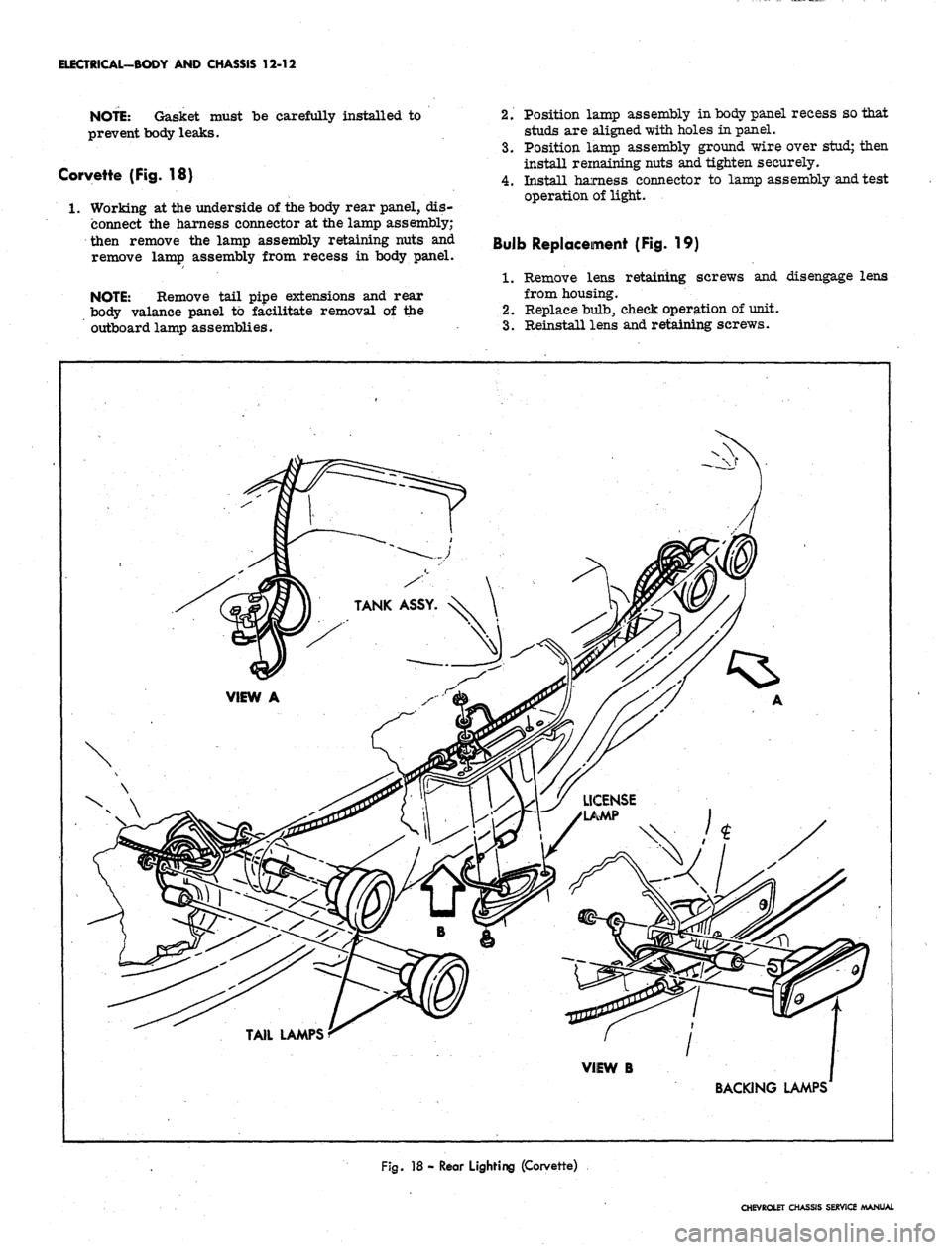
Corvette (Fig. 18)
1.
Working at the underside of the body rear panel, dis-
connect the harness connector at the lamp assembly;
then remove the lamp assembly retaining nuts and
remove lamp assembly from recess in body panel.
NOTE:
Remove tail pipe extensions and rear
body valance panel to facilitate removal of the
outboard lamp assemblies.
2.
Position lamp assembly in body panel recess so that
studs are aligned with holes in panel.
3.
Position lamp assembly ground wire over stud; then
install remaining nuts and tighten securely.
4.
Install harness connector to lamp assembly and test
operation of light.
Bulb Replacement (Fig. 19)
1.
Remove lens retaining screws and disengage lens
from housing.
2.
Replace bulb, check operation of unit.
3.
Reinstall lens and retaining screws.
VIEW B
BACKING LAMPS
Fig.
18 - Rear Lighting (Corvette)
CHEVROLET CHASSIS SERVICE MANUAL
Page 526 of 659
ELECTRICAL-BODY AND CHASSIS 12-14
BACKING LAMPS
lamp Housing Replacement (Fig. 19)
Bumper Installation
1.
Remove two screws retaining housing assembly in
the bumper and remove housing.
'2.
Disconnect lamp wire assembly connector from wir-
ing harness.
3.
Remove lens retaining screws, lens and bulb from
housing assembly and transfer to new housing unit.
4.
Connect lamp wiring assembly to harness assembly,
housing and check operation of lamp.
•5.
Position lamp assembly in place and install retaining
screws.
Corvette (Fig. 18)
1.
Remove license plate and bracket assembly.
2.
Remove tailpipe extensions and rear body valance
panel.
3.
Remove backing lamp attaching nuts.
4.
Disengage backing lamp assembly from body opening
and disconnect wiring harness at rear of lamp.
5. Transfer bulb, gasket and lens to replacement
housing.
6. Connect chassis wiring connector to housing and po-
sition lamp assembly to body opening.
7. Attach ground wire to housing and install retaining
nuts to housing.
8. Install body valance panel.
9. Position license plate assembly to body and install
retaining screws.
LICENSE PLATE LAMP SERVICE
Lamp Housing
1.
Remove the lamp assembly retaining screws and re-
move lamp assembly from mounting location (rear
bumper center face bar most models). On Corvette
models remove rear valance panel.
2.
Disconnect lamp wiring from chassis harness con-
nector (inside trunk on some models).
3.
Force grommet and Wiring down through body open-
ing (where applicable) and remove assembly from
vehicle.
4.
To install replacement unit, insert grommet and wir-
ing through body opening where applicable and con-
nect wiring to chassis harness.
5. Position assembly and install retaining screws. On
Corvette models make sure ground wire is properly
installed.
6. Check operation of lamp assembly.
iuib Replacement
1.
Remove lens retaining screws and lens.
NOTE:
On Camaro models loosen housing re-
taining screws.
2.
Remove and replace bulb.
3.
Position lens and install retaining screws.
AUTOMATIC TRANSMISSION
QUADRANT LAMP REPLACEMENT
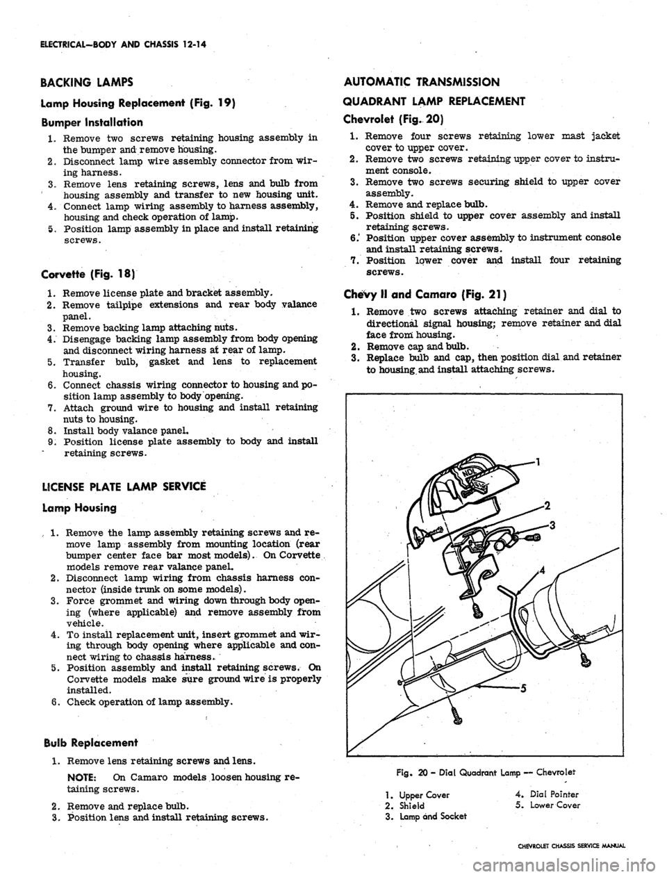
Chevrolet (Fig. 20)
1.
Remove four screws retaining lower mast jacket
cover to upper cover.
2.
Remove two screws retaining upper cover to instru-
ment console.
3.
Remove two screws securing shield to upper cover
assembly.
4.
Remove and replace bulb.
5. Position shield to upper cover assembly and install
retaining screws.
6.' Position upper cover assembly to instrument console
and install retaining screws.
7. Position lower cover and install four retaining
screws.
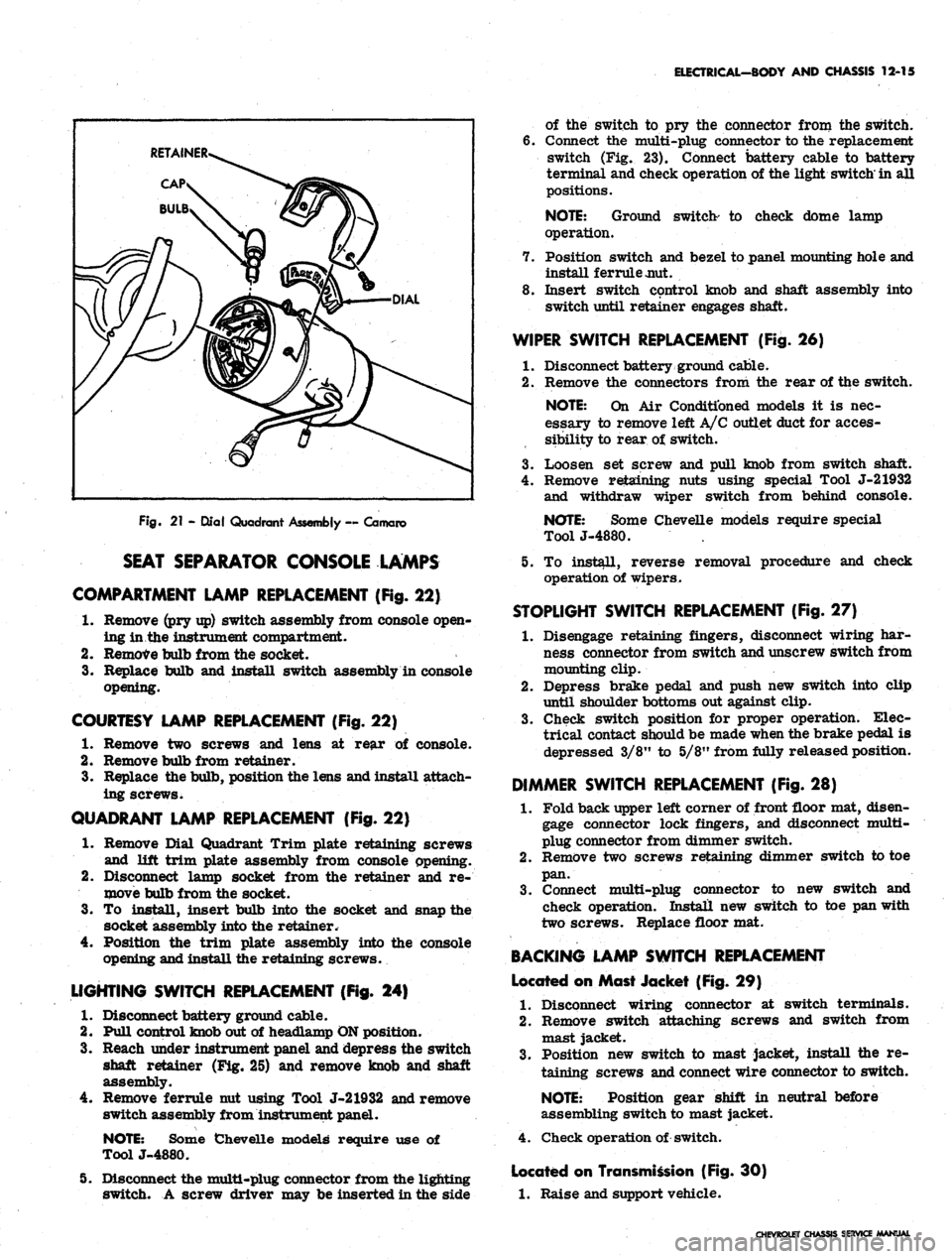
Chevy II and Camaro (Fig. 21)
1.
Remove two screws attaching retainer and dial to
directional signal housing; remove retainer and dial
face from housing.
2.
Remove cap and bulb.
3.
Replace bulb and cap, then position dial and retainer
to housing.and install attaching screws.
Fig.
20 - Dial Quadrant Lamp — Chevrolet
1.
Upper Cover
2.
Shield
3. Lamp and Socket
4.
Dial Pointer
5.
Lower Cover
CHEVROLET CHASSIS SERVICE MANUAL
Page 527 of 659
ELECTRICAL-BODY AND CHASSIS 12-15
Fig.
21 - Qlal Quadrant Assembly ~ Camaro
SEAT SEPARATOR CONSOLE LAMPS
COMPARTMENT LAMP REPLACEMENT (Fig.
22)
1.
Remove (pry up) switch assembly from console open-
ing in.the instrument compartment.
2.
Remove bulb from the socket.
3.
Replace bulb and install switch assembly in console
opening.
COURTESY LAMP REPLACEMENT (Fig. 22)
1.
Remove two screws and lens at rear of console.
2.
Remove bulb from retainer.
3.
Replace the bulb, position the lens and install attach-
ing screws.
QUADRANT LAMP REPLACEMENT (Fig. 22)
1.
Remove Dial Quadrant Trim plate retaining screws
and lift trim plate assembly from console opening.
2.
Disconnect lamp socket from the retainer and re-
move bulb from the socket.
3.
To install, insert bulb into the socket and snap the
socket assembly into the retainer.
Position the trim plate assembly into the console
opening and install the retaining screws.
4.
LIGHTING SWITCH REPLACEMENT (Fig. 24)
1.
Disconnect battery ground cable.
2.
Pull control knob out of headlamp ON position.
3.
Reach under instrument panel and depress the switch
shaft retainer (Fig. 25) and remove knob and shaft
assembly.
4.
Remove ferrule nut using Tool J-21932 and remove
switch assembly from instrument panel.
NOTE:
Some Chevelle models require use of
ToolJ-4880.
5. Disconnect the multi-plug connector from the lighting
switch. A screw driver may be inserted in the side
of the switch to pry the connector from the switch.
6. Connect the multi-plug connector to the replacement
switch (Fig. 23). Connect battery cable to battery
terminal and check operation of the light switch'in all
positions.
NOTE:
Ground switch- to check dome lamp
operation.
7. Position switch and bezel to panel mounting hole and
install ferrule jmt.
8. Insert switch control knob and shaft assembly into
switch until retainer engages shaft.
WIPER SWITCH REPLACEMENT (Fig. 26)
1.
Disconnect battery ground cable.
2.
Remove the connectors from the rear of the switch.
NOTE:
On Air Conditioned models it is nec-
essary to remove left A/C outlet duct for acces-
sibility to rear of switch.
3.
Loosen set screw and pull knob from switch shaft.
4.
Remove retaining nuts using special Tool J-21932
and withdraw wiper switch from behind console.
NOTE:
Some Chevelle models require special
ToolJ-4880.
5. To install, reverse removal procedure and check
operation of wipers.
STOPLIGHT SWITCH REPLACEMENT (Fig. 27)
1.
Disengage retaining fingers, disconnect wiring har-
ness connector from switch and unscrew switch from
mounting clip.
2.
Depress brake pedal and push new switch into clip
until shoulder bottoms out against clip.
3.
Check switch position for proper operation. Elec-
trical contact should be made when the brake pedal is
depressed 3/8" to 5/8" from fully released position.
DIMMER SWITCH REPLACEMENT (Fig. 28)
1.
Fold back upper left corner of front floor mat, disen-
gage connector lock fingers, and disconnect multi-
plug connector from dimmer switch.
2.
Remove two screws retaining dimmer switch to toe
pan.
3.
Connect multi-plug connector to new switch and
check operation. Install new switch to toe pan with
two screws. Replace floor mat.
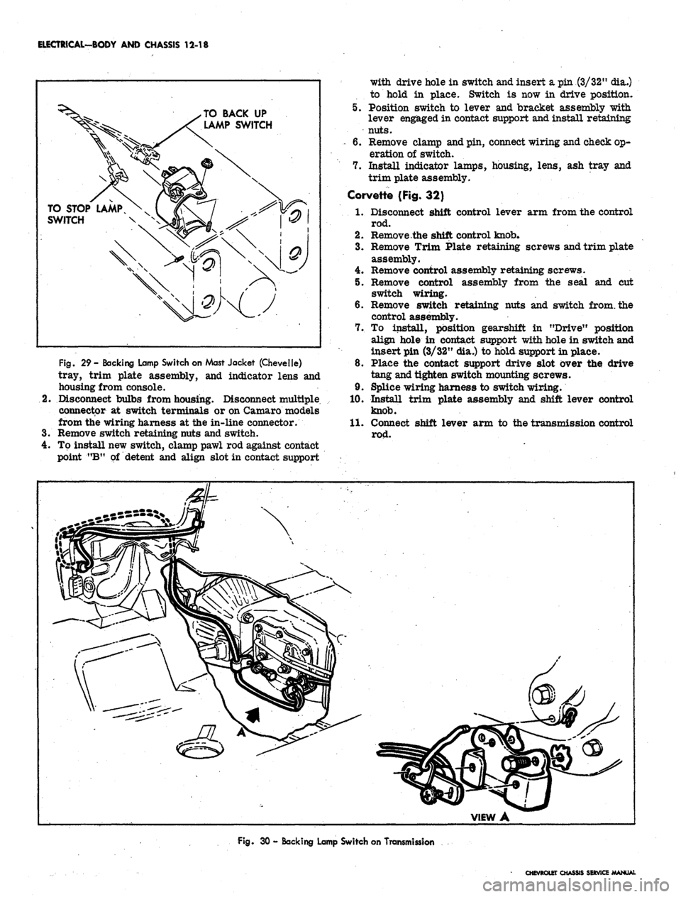
BACKING LAMP SWITCH REPLACEMENT
Located on Mast Jacket (Fig. 29)
1.
Disconnect wiring connector at switch terminals.
2.
Remove switch attaching screws and switch from
mast jacket.
3.
Position new switch to mast jacket, install the re-
taining screws and connect wire connector to switch.
NOTE:
Position gear shift in neutral before
assembling switch to mast jacket.
4.
Check operation of switch.
Located on Transmission (Fig. 30)
1.
Raise and support vehicle.
CHEVROLET CHASSIS SERVICE MANUAL
Page 530 of 659
ELECTRICAL-BODY AND CHASSIS 12-18
TO BACK UP
LAMP SWITCH
TO STOP LAMP
SWITCH
Fig.
29 - Backing Lamp Switch on Mast Jacket (Chevelle)
tray, trim plate assembly, and indicator lens and
housing from console.
Disconnect bulbs from housing. Disconnect multiple
connector at switch terminals or on Camaro models
from the wiring harness at the in-line connector.
Remove switch retaining nuts and switch.
Tp install new switch, clamp pawl rod against contact
point "B" of detent and align slot in contact support
6.
7.
with drive hole in switch and insert a pin (3/32" dia.)
to hold in place. Switch is now in drive position.
Position switch to lever and bracket assembly with
lever engaged in contact support and install retaining
nuts.
Remove clamp and pin, connect wiring and check op-
eration of switch.
Install indicator lamps, housing, lens, ash tray and
trim plate assembly.
Corvette {Fig. 32)
1.
Disconnect shift control lever arm from the control
rod.
2.
Remove the shift control knob.
3.
Remove Trim Plate retaining screws and trim plate
assembly.
4.
Remove control assembly retaining screws.
5. Remove control assembly from the seal and cut
switch wiring.
6. Remove switch retaining nuts and switch from, the
control assembly.
7. To install, position gearshift in "Drive" position
align hole in contact support with hole in switch and
insert pin (3/32" dia.) to hold support in place.
8. Place the contact support drive slot over the drive
tang and tighten switch mounting screws.
9. Splice wiring harness to switch wiring.
10.
Install trim plate assembly and shift lever control
knob.
11.
Connect shift lever arm to the transmission control
Fig.
30 - Backing Lamp Switch on Transmission
CHEVROLET CHASSIS SERVICE MANUAL
Page 531 of 659

ELECTRICAL-BODY AND CHASSIS 12-19
VIEW A
•CONTACT SUPPORT
DRIVE SLOT IN LINE
WITH HOLE IN SWITCH
PAWL
CONTACT POINT B
CONTACT SUPPORT
DRIVE SLOT IN LINE
WITH HOLE IN SWITCH
FLOOR SHIFT
(EXCEPT CAMARO)
COLUMN SH
Fig.
31 - Neutral Safety Switches
PARKING BRAKE ALARM SWITCH REPLACEMENT
Corvette (Fig. 33)
1.
Remove seat belt retainer and parking brake cover
assembly from center console.
2.
Disconnect wire from brake alarm switch.
3.
Remove retaining screw and switch from
reinforcement.
4.
Position new switch to reinforcement and install re-
taining screw.
5. Connect switch wire and check operation of switch.
6. Install cover and seat belt retainer assembly.
Chevrolet, Chevelle, Chevy II and Camaro (Fig. 34)
1.
Disconnect wiring connector at switch terminal.
2.
Remove nut and lock washer or retaining bolt and
disengage switch from brace.
3.
To install, reverse removal procedure.
INSTRUMENT PANEL COMPARTMENT
LAMP/SWITCH REPLACEMENT
1.
Disconnect battery ground cable.
2.
Reach into glove box, depress bulb in end of switch
and turn counterclockwise to remove bulb.
3..
Remove switch from socket. Carefully detach wire
and terminal from switch.
NOTE:
On some model switches, the wire and
terminal cannot be detached from the switch
making it necessary to cut and splice the switch
wire.
4.
Insert wire and terminal into new switch.
5. Push switch into place and install bulb by setting it in
place, depressing and turning it clockwise.
CIGARETTE LIGHTER REPLACEMENT
Chevrolet, Chevy II, Camaro and Corvette (Fig. 23)
1.
Disconnect battery ground cable.
2.
Disconnect wire connector at rear of lighter unit
under dash.
3.
Remove retainer from rear of housing assembly and
disengage lighter unit from panel.
4.
To install, reverse removal procedure.
Chevelle (Fig. 35)
1.
Disconnect battery ground cable.
CHEVROLET CHASSIS SERVICE MANUAL
Page 533 of 659
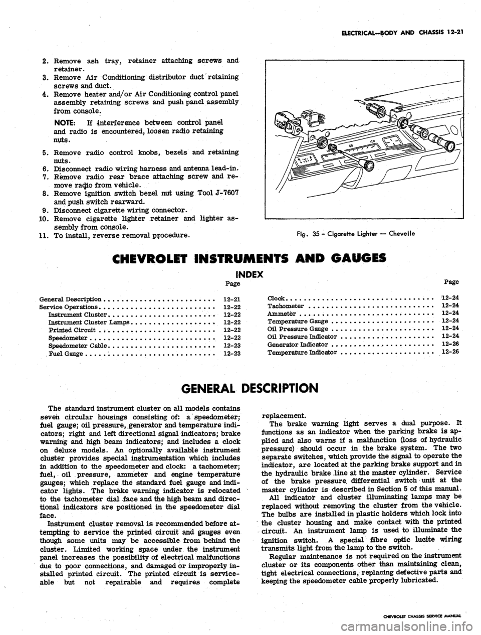
ELECTRICAL-BODY AND CHASSIS 12-21
2.
Remove ash tray, retainer attaching screws and
retainer.
3.
Remove Air Conditioning distributor
duct'
retaining
screws and duct.
4.
Remove heater and/or Air Conditioning control panel
assembly retaining screws and push panel assembly
from console.
NOTE:
If interference between control panel
and radio is encountered, loosen radio retaining
nuts.
5. Remove radio control knobs, bezels and retaining
nuts.
6. Disconnect radio wiring harness and antenna lead-in.
7. Remove radio rear brace attaching screw and re-
move ra(Jio from vehicle.
8. Remove ignition switch bezel nut using Tool J-7607
and push switch rearward.
9. Disconnect cigarette wiring connector.
10.
Remove cigarette lighter retainer and lighter as-
sembly from console.
11.
To install, reverse removal procedure.
Fig.
35 - Cigarette Lighter — Chevelle
CHEVROLET INSTRUMENTS AND GAUGES
INDEX
Page
General Description 12-21
Service Operations 12-22
Instrument Cluster........................ 12-22
Instrument Cluster Lamps 12-22
Printed Circuit .
* •
12-22
Speedometer 12-22
Speedometer Cable 12-23
Fuel Gauge 12-23
Page
Clock 12-24
Tachometer 12-24
Ammeter . . 12-24
Temperature Gauge 12-24
Oil Pressure Gauge 12-24
Oil Pressure Indicator 12-24
Generator Indicator 12-26
Temperature Indicator 12-26
GENERAL DESCRIPTION
The standard instrument cluster on all models contains
seven circular housings consisting of: a speedometer;
fuel gauge; oil pressure, generator and temperature indi-
cators; right and left directional signal indicators; brake
warning and high beam indicators; and includes a clock
on deluxe models. An optionally available instrument
cluster provides special instrumentation which includes
in addition to the speedometer and clock: a tachometer;
fuel, oil pressure, ammeter and engine temperature
gauges; which replace the standard fuel gauge and indi-
cator lights. The brake warning indicator is relocated
to the tachometer dial face and the high beam and direc-
tional indicators are positioned in the speedometer dial
face.
Instrument cluster removal is recommended before at-
tempting to service the printed circuit and gauges even
though some units may be accessible from behind the
cluster. Limited working space under the instrument
panel increases the possibility of electrical malfunctions
due to poor connections, and damaged or improperly in-
stalled printed circuit. The printed circuit is service-
able but not repairable and requires complete
replacement.
The brake warning light serves a dual purpose. It
functions as an indicator when the parking brake is ap-
plied and also warns if a malfunction (loss of hydraulic
pressure) should occur in the brake system. The two
separate switches, which provide the signal to operate the
indicator, are located at the parking brake support and in
the hydraulic brake line at the master cylinder. Service
of the brake pressure, differential switch unit at the
master cylinder is described in Section 5 of this manual.
All indicator and cluster illumihating lamps may be
replaced without removing the cluster from the vehicle.
The bulbs are installed in plastic holders which lock into
the cluster housing and make contact with the printed
circuit. An instrument lamp is used to illuminate the
ignition switch. A special fibre optic lucite wiring
transmits light from the lamp to the switch.
Regular maintenance is not required on the instrument
cluster or its components other than maintaining clean,
tight electrical connections, replacing defective parts and
keeping the speedometer cable properly lubricated.
CHEVROLET CHASSIS SERVICE MANUAL
Page 534 of 659
ELECTRICAL-BODY AND CHASSIS 12-22
SERVICE OPERATIONS
INSTRUMENT CLUSTER
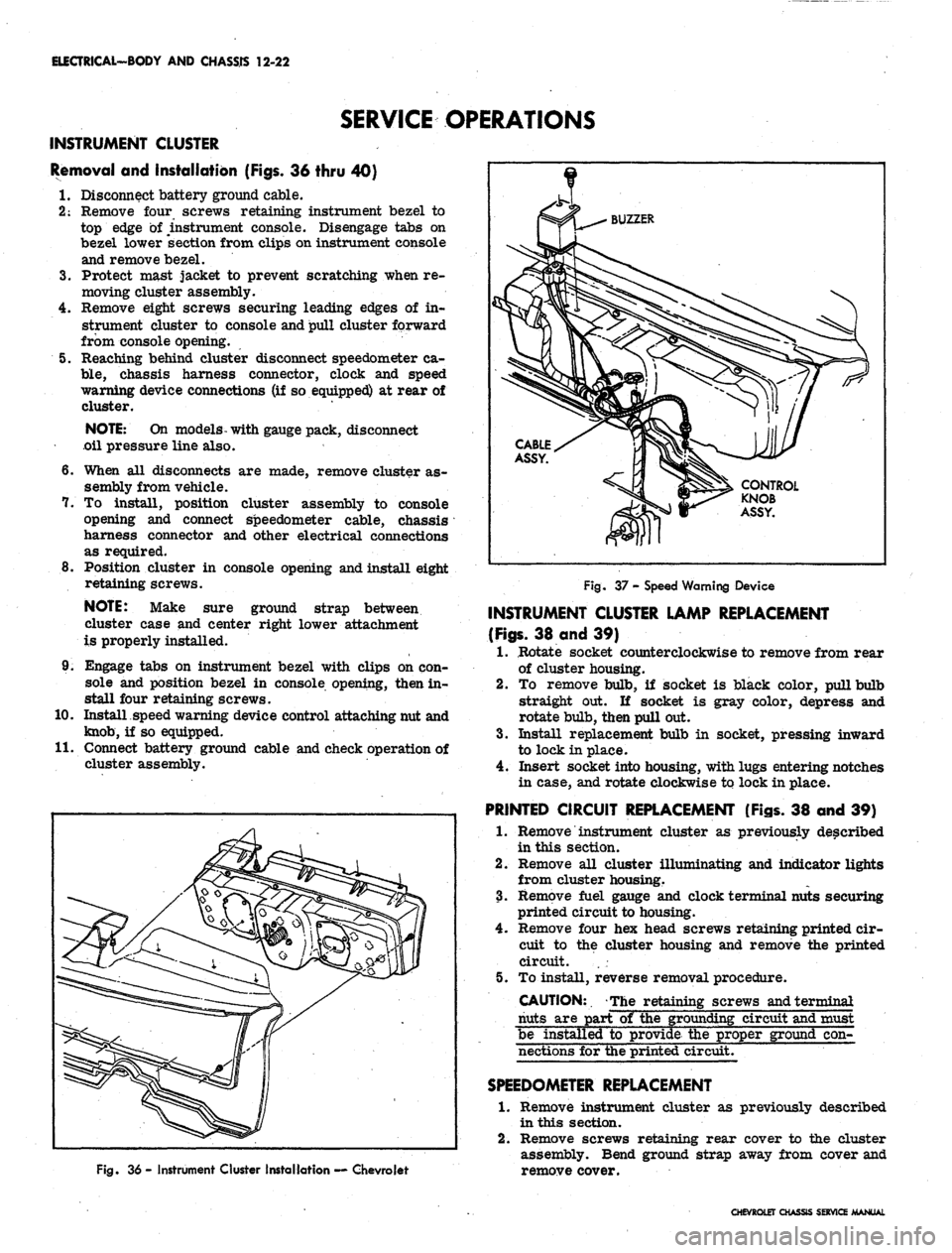
Removal and Installation (Figs. 36 thru 40)
I. Disconnect battery ground cable.
2:
Remove four screws retaining instrument bezel to
top edge of instrument console. Disengage tabs on
bezel lower section from clips on instrument console
and remove bezel.
3.
Protect mast jacket to prevent scratching when re-
moving cluster assembly.
4.
Remove eight screws securing leading edges of in-
strument cluster to console and pull cluster forward
from console opening.
5. Reaching behind cluster disconnect speedometer ca-
ble,
chassis harness connector, clock and speed
warning device connections (if so equipped) at rear of
cluster.
NOTE:
On models- with gauge pack, disconnect
oil pressure line also.
6. When all disconnects are made, remove cluster as-
sembly from vehicle.
7. To install, position cluster assembly to console
opening and connect speedometer cable, chassis
harness connector and other electrical connections
as required.
8. Position cluster in console opening and install eight
retaining screws.
NOTE:
Make sure ground strap between
cluster case and center right lower attachment
is properly installed.
9. Engage tabs on instrument bezel with clips on con-
sole and position bezel in console opening, then in-
stall four retaining screws.
10.
Install speed warning device control attaching nut and
knob,
if so equipped.
II.
Connect battery ground cable and check operation of
cluster assembly.
Fig. 36 - Instrument Cluster Installation — Chevrolet
Fig. 37 - Speed Warning Device
INSTRUMENT CLUSTER LAMP REPLACEMENT
(Figs.
38 and 39)
1.
Rotate socket counterclockwise to remove from rear
of cluster housing.
2.
To remove bulb, if socket is black color, pull bulb
straight out. If socket is gray color, depress and
rotate bulb, then pull out.
3.
Install replacement bulb in socket, pressing inward
to lock in place.
4.
Insert socket into housing, with lugs entering notches
in case, and rotate clockwise to lock in place.
PRINTED CIRCUIT REPLACEMENT (Figs. 38 and 39)
1.
Remove instrument cluster as previously described
in this section.
2.
Remove all cluster illuminating and indicator lights
from cluster housing.
3.
Remove fuel gauge and clock terminal nuts securing
printed circuit to housing.
4.
Remove four hex head screws retaining printed cir-
cuit to the cluster housing and remove the printed
circuit. . .
5. To install, reverse removal procedure.
CAUTION:. The retaining screws and terminal
nuts are part of the grounding circuit and must
be installed to provide the proper ground con-
nections for the printed circuit.
SPEEDOMETER
REPLACEMENT
1.
Remove instrument cluster as previously described
in this section.
2.
Remove screws retaining rear cover to the cluster
assembly. Bend ground strap away from cover and
remove cover.
CHEVROLET CHASSIS SERVICE MANUAL
Page 538 of 659
ELECTRICAL-BODY
AND
CHASSIS
12-26
•
Low oil
pressure
• High engine temperature
• Defective wiring
or
switch
connector from sender
in block above starter
on
and
at
left front
of
distributor
on V-8
Sending Unit Replacement
1.
Disconnect wiring harness
unit terminal (located
L-6 engines
engines).
2.
Remove sender unit using Tool J-21757
or 12
point
socket, replace with
new
unit
and
check operation.
GENERATOR INDICATOR
1.
Ignition
on,
Engine
not
Running
and
Telltale Light
Off.
• Indicator bulb burned out, replace bulb.
• Open circuit
or
loose connection
in the
telltale
light circuit.
2.
telltale Light Stays
on
after Engine
is
Started.
If indicator light does
not go out at
engine idle
speed, refer
to
Charging Systems under Engine
Electrical, Section
6Y.
TEMPERATURE (COOLING SYSTEM) INDICATOR
The temperature indicator circuit consists
of two re-
motely located units, indicator gauge
and
engine sender
unit.
The
indicator gauge, located
in the
instrument
panel, consists
of a
red light which will indicate
an
over-
heated engine condition.
Engine Sender Unit Replacement
1.
Drain engine cooling system
to a
level below unit.
2.
Remove sender unit (located
in the
inlet manifold
near water pump housing
on V-8
engines and
in the
cylinder head near
an
exhaust port
oh L-6
engines)
and replace with new unit.
3.
Refill cooling system
and
check operation
of
unit.
CHEVELLE INSTRUMENTS AND GAUGES
INDEX
Page
General Description
* *
i2-26
Service Operations
12-26
Instrument Panel
12-26
Instrument Cluster.
12-26
Fuel Gauge and/or Ammeter
12-27
Clock,
i 12-27
Speedometer
12-27
Page
Speedometer Cable
.
. 12-27
Temperature Gauge
12-29
Oil Pressure Gauge
12-29
Indicator Lights.
. 12-29
Oil Pressure Indicator
12-29
Generator Indicator
. . 12-29
• Temperature Indicator
12-29
GENERAL DESCRIPTION
The Chevelle instrument cluster assembly consists
of:
a speedometer;
a
fuel gauge;
a
generator,
an
engine
tem-
perature and an
oil
pressure indicator lamp, and includes
a clock
on
deluxe models.
On
super sport models,
am-
meter, coolant temperature
and oil
pressure gauges
re-
place
the
appropriate indicator lights. Except
for the
speedometer,
all of the
indicator lamps, instruments
and
gauges
of
these clusters may
be
serviced without remov-
ing
the
instrument cluster assembly from
the
vehicle.
In addition
to the
instrument indicator lamps,
a
brake
warning lamp
is
included
in the
cluster
as
standard
equipment.
The
indicator
is
connected
to the
parking
brake
and
brake pressure differential switches
and
serves
a
dual function.
It
lights when the parking brake
is applied
and
also when
the
brake pedal
is
applied,
if a
malfunction should occur
in the
brake system
due to a
loss
of
hydraulic pressure. Servicing
of the
hydraulic
pressure differential switch
is
covered
in
Section
5 of
this manual.
Regular maintenance
is not
required on the instrument
cjLuster
or its
components other than maintaining dean
and tight electrical connections, replacing defective parts
and keeping
the
speedometer cable properly lubricated.
SERVICE OPERATIONS
INSTRUMENT PANEL ASSEMBLY
INSTRUMENT CLUSTER (Figs.
41
thru
44)
Removal
1.
Disconnect battery ground cable.
2.
Remove steering coupling bolt and disconnect steer-
ing shaft from coupling.
3.
Loosen mast jacket lower clamp.
4.
Remove
air
conditioning center distributor duct
(if
so equipped).
5. Remove radio rear support bracket screw.
6. Remove mast jacket upper support clamp and retain-
ing bolts from lower support (refer
to
Section
9,
Steering).
CAUTION: Cover mast jacket
and
parl
brake handle with
a
suitable material
to
prevc
scratching.
7.
Disconnect speedometer cable
at
rear
of
cluster
housing
and
speed warning control knob
at
panel
(if
so equipped).
8. Remove instrument panel retaining screws (nine
upper and five lower).
.
9. Working under the console remove four lower retain-
ing screws from instrument cluster housing.
10.
Pull instrument panel assembly from console and
lay
forward on mast jacket.
11.
Disconnect wiring harness, cluster lamps and wiring
CHEVROLET CHASSIS SERVICE MANUAL
Page 541 of 659
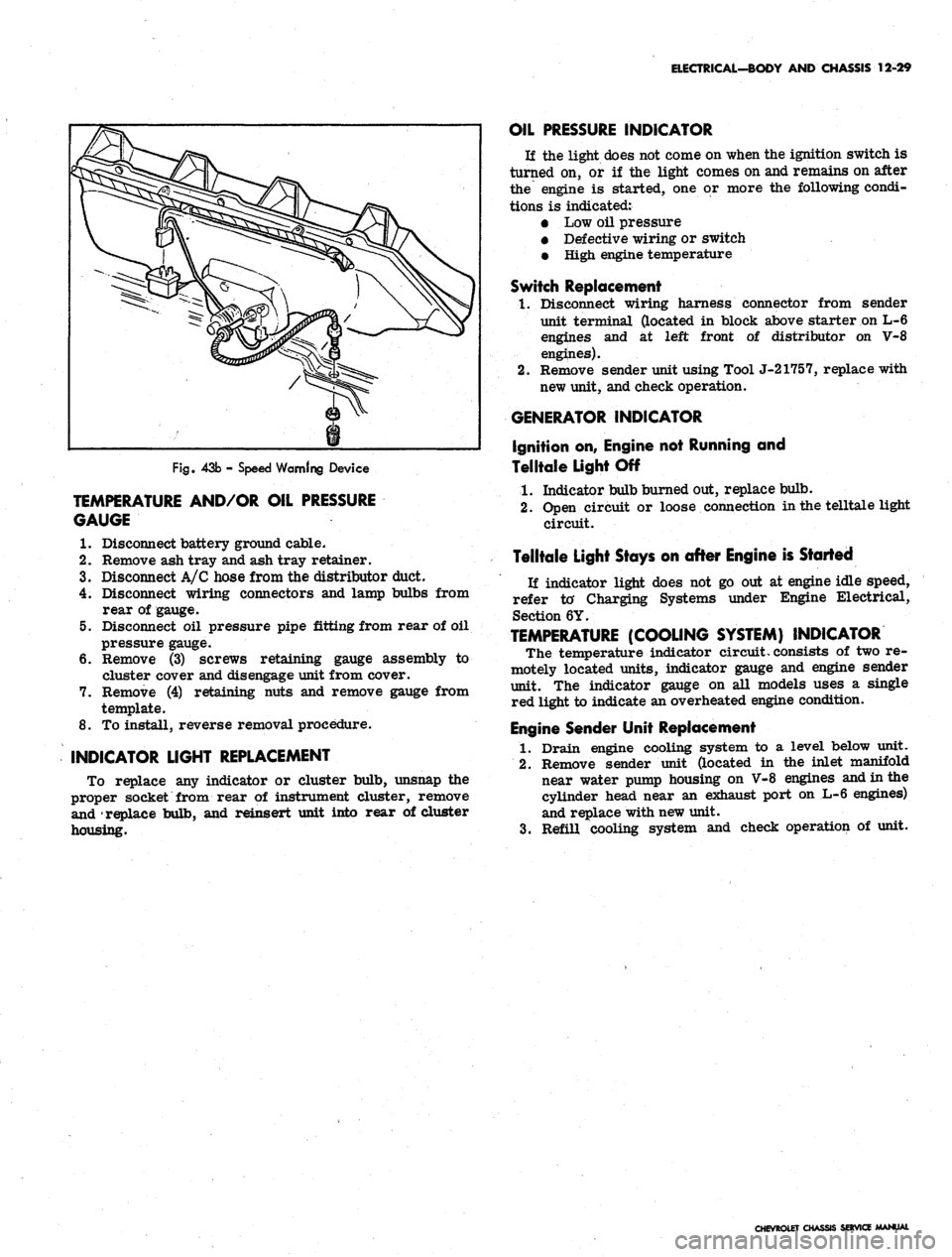
ELECTRICAL-BODY AND CHASSIS 12-29
Fig.
43b - Speed Warning Device
TEMPERATURE AND/OR OIL PRESSURE
GAUGE
1.
Disconnect battery ground cable.
2.
Remove ash tray and ash tray retainer.
3.
Disconnect A/C hose from the distributor duct.
4.
Disconnect wiring connectors and lamp bulbs from
rear of gauge.
5. Disconnect oil pressure pipe fitting from rear of oil
pressure gauge.
6. Remove (3) screws retaining gauge assembly to
cluster cover and disengage unit from cover.
7. Remove (4) retaining nuts and remove gauge from
template.
8. To install, reverse removal procedure.
INDICATOR LIGHT REPLACEMENT
To replace any indicator or cluster bulb, unsnap the
proper socket from rear of instrument cluster, remove
and replace bulb, and reinsert unit into rear of cluster
housing.
OIL PRESSURE INDICATOR
If the light does not come on when the ignition switch is
turned on, or if the light comes on and remains on after
the engine is started, one or more the following condi-
tions is indicated:
• Low oil pressure
• Defective wiring or switch
• High engine temperature
Switch Replacement
1.
Disconnect wiring harness connector from sender
unit terminal (located in block above starter on L-6
engines and at left front of distributor on V-8
engines).
2.
Remove sender unit using Tool J-21757, replace with
new unit, and check operation.
GENERATOR INDICATOR
Ignition on, Engine not Running and
Telltale Light Off
1.
Indicator bulb burned out, replace bulb.
2.
Open circuit or loose connection in the telltale light
circuit.
Telltale Light Stays on after Engine is Started
If indicator light does not go out at engine idle speed,
refer to' Charging Systems under Engine Electrical,
Section 6Y.
TEMPERATURE
(COOLING
SYSTEM)
INDICATOR
The temperature indicator circuit, consists of two re-
motely located units, indicator gauge and engine sender
unit. The indicator gauge on all models uses a single
red light to indicate an overheated engine condition.
Engine Sender Unit Replacement
1.
Drain engine cooling system to a level below unit.
2.
Remove sender unit (located in the inlet manifold
near water pump housing on V-8 engines and in the
cylinder head near an exhaust port on L-6 engines)
and replace with new unit.
3.
Refill cooling system and check operation of unit.
CHEVROLET CHASSIS SERVICE MANUAL