relay CHEVROLET CAMARO 1967 1.G Chassis Workshop Manual
[x] Cancel search | Manufacturer: CHEVROLET, Model Year: 1967, Model line: CAMARO, Model: CHEVROLET CAMARO 1967 1.GPages: 659, PDF Size: 114.24 MB
Page 41 of 659
HEATER AND AIR CONDITIONING 1A-18
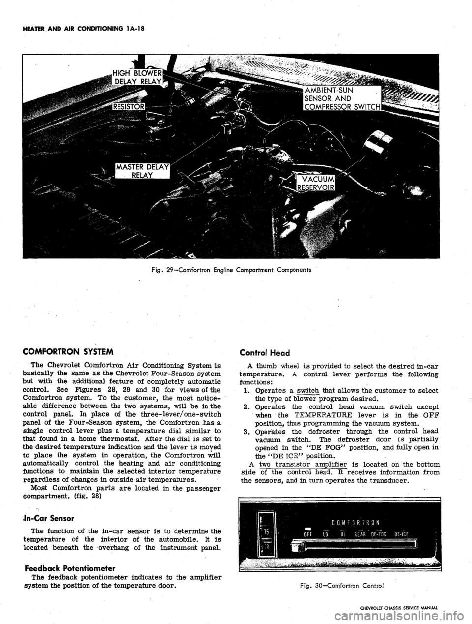
HIGH BLOWER
i DELAY RELAY
AMBIENT-SUN
SENSOR AND
COMPRESSOR SWITCH
Fig. 29—Comfortron Engine Compartment Components
COMFORTRON SYSTEM
The Chevrolet Comfortron Air Conditioning System is
basically the same as the Chevrolet Four-Season system
but with the additional feature of completely automatic
control. See Figures 28, 29 and 30 for views of the
Comfortron system. To the customer, the most notice-
able difference between the two systems, will be in the
control panel. In place of the three-lever/one-switch
panel of the Four-Season system, the Comfortron has a
single control lever plus a temperature dial similar to
that found in a home thermostat. After the dial is set to
the desired temperature indication and the lever is moved
to place the system in operation, the Comfortron will
automatically control the heating and air conditioning
functions to maintain the selected interior temperature
regardless of changes in outside air temperatures.
Most Comfortron parts are located in the passenger
compartment, (fig. 28)
Jn-Car Sensor
The function of the in-car sensor is to determine the
temperature of the interior of the automobile. It is
located beneath the overhang of the instrument panel.
Feedback Potentiometer
The feedback potentiometer indicates to the amplifier
system the position of the temperature door.
Control Head
A thumb wheel is provided to select the desired in-car
temperature. A control lever performs the following
functions:
1.
Operates a switch that allows the customer to select
the type of blower program desired.
2.
Operates the control head vacuum switch except
when the TEMPERATURE lever is in the OFF
position, thus programming the vacuum system.
3.
Operates the defroster through the control head
vacuum switch. The defroster door is partially
opened in the "DE FOG" position, and fully open in
the "DE ICE" position.
A two transistor amplifier is located on the bottom
side of the control head. It receives information from
the sensors, and in turn operates the transducer.
Fig. 30—Comfortron Control
CHEVROLET CHASSIS SERVICE MANUAL
Page 42 of 659
HEATER AND AIR CONDITIONING 1A-19
Transducer
The transducer will produce a vacuum output that is
completely adjustable by varying the input voltage which
is provided by the amplifier. An increase in the applied
voltage results in a reduced vacuum output.
Power Servo
The power servo receives a vacuum signal from the
transducer, and it is capable of assuming any position
that is called for by the sensors, amplifier, and trans-
ducer. The power servo performs the following functions:
1.
Positions the temperature mix door via the tern-
perature door link. The position of this door~"de-
termihes the portions of hot and cold air being
blended and discharged into the car.
2.
Operates the power servo vacuum valve which de-
termines the air flow paths for heating and air
conditioning.
3.
Contains a printed circuit board which controls the
blower speed. The power servo position determines
the blower speed, but the control lever switch can
override the blower program depending upon the
customer's preference.
4.
Contains the "Hi" blower delay thermistor and the
"master delay thermistor".
Outside Air Diaphragm
When there is no vacuum applied to the hose, the out-
side air door is closed under spring tension. With the
door closed, air is taken from the inside of the auto-
mobile and re-circulated. Applying vacuum to the dia-
phragm opens the door for outside air.
Mode Door Diaphragm
Located behind the duct work, the mode door diaphragm
directs the air flow out either the air conditioning outlets,
the heater floor outlet, or both the heater and air con-
ditioning outlets. This is a push-pull type diaphragm
actuated by vacuum through two hoses and controlled by
the power servo vacuum switch.
Defroster Door
The defroster door is in the defog position until vacuum
is applied to the actuator to obtain either full heat or full
de-ice position.
High Blower Delay Thermistor
The high blower delay thermistor is located on the
power servo housing under the power servo vacuum valve
and printed circuit board assemblies. The function of the
thermistor is to operate the blower at a reduced speed
when the control is in the HI FRONT position until the
residual cold air is discharged from the duct work. This
function occurs when the blower first comes "on" in cold
weather.
Vacuum Tank
During heavy acceleration, the vacuum supply from
the carburetor drops. The vacuum tank, using a^ check
valve, stores vacuum so that under these conditions
vacuum will be available for the Comfortron.
Thermal Vacuum Valve (Hot Water Vacuum Switch)
When engine coolant temperature reaches 75°F, the
valve opens and supplies vacuum to the outside air door
if the system is calling for outside air.
Master Delay Thermister
This thermistor delays the initial operation of the
blower when the system is in the heat mode. In cold
weather this allows outside ram air to flow through the
system thereby purging the cold air in the ducts gradually
until the coolant reaches about 105°F. Then, the termis-
tor passes enough current to energize the master delay
relay which powers the blower at about nine volts.
Vacuum Relay Valve
This relay valve will shut off transducer vacuum to the
power servo whenever the vacuum from the engine intake
manifold falls below the vacuum in the power servo
supply line (engine stopped or operating at low manifold
vacuum). This causes the power servo to be held in
position when the vacuum supply falls too low to maintain
servo control.
Vacuum Bleeder
A vacuum bleeder insures that the outside air door will
close (diaphragm will bleed down) after the system has
been shut down. This prevents outside air from entering
when starting the system on a cold day before the engine
coolant temperature reaches 75°F.
Sun—Ambient Sensor
The sun-ambient sensor measures the temperature of
the air entering the air intake grille in front of the wind-
shield. The sensor is exposed to sun light so that it can
lower the in-car temperature slightly when the sun
is shining.
Ambient Switch
The ambient switch operates the air conditioning com-
pressor clutch. When the outside temperature is above
40° F. the switch will be closed and the compressor will
be running. This switch is included as| part of the sun-
ambient sensor assembly, but operates independently.
Resistor Assembly
The blower resistors are located in the evaporator
housing. The printed circuit board switch in the power
servo determines which of the resistors is being used,
and as in conventional systems, the resistors control the
blower speed.
System Operation
When starting the Comfortron System in cold weather,
the following sequence of events occurs:
1.
Initially the system is inoperative. In LO FRONT
position the master delay thermistor is warming
(self-heating because current is flowing through it)
CHEVROLET CHASSIS SERVICE MANUAL
Page 43 of 659
HEATER AND AIR CONDITIONING 1A-20
and its resistance is decreasing. In the HI FRONT
position, two thermistors (the master delay and high
blower delay thermistors) are warming. The air
door is in recirculation position until the engine
coolant reaches 75 degrees.
2.
The coolant reaches then 75 degrees and the thermal
vacuum valve opens applying vacuum to the air door
to admit outside air (unless the temperature dial is
set for cooling). Ram air will flow through the sys-
tem when the car is moving.
3.
Next, the master delay thermistor attains the tem-
perature at which it will pass sufficient current to
close the circuit through the master delay relay.
The relay circuit powers the blower motor at 9 volts.
4.
If the control is in the HI FRONT position, the high
blower delay thermistor will close the circuit
through the high blower relay which supplies full
available voltage to the blower motor. This function
occurs after the master delay thermistor has taken
effect because the high blower delay thermistor
uses the master delay type thermistor with a 10 ohm
1/4 watt resistor connected in
.
series. The nigh
blower delay thermistor must then warm to a higher
temperature than the master delay thermistor before
its resistance (plus that of the 10 ohm resistor)
drops enough to actuate the high blower relay.
5. If the controls are set for DE ICE, full outside air
and full voltage to the blower motor are effective
immediately regardless of temperatures or elapsed
times o
In accomplishing automatic control, the system follows
three steps to transform an electronic signal into me-
chanical energy through which the control is achieved.
Electronic Circuit
Two temperature sensors (Thermistors), and the duct
potentiometer connected in series, are located so as to
sense the temperature of the outside air, inside air and
system output air. The resistance of each sensor will
vary according to its temperature. The control head
temperature dial varies in resistance as it is adjusted by
the operator to suit his comfort requirements. The
resistance of the temperature dial control is applied
directly to the amplifier and is not in series with the
sensors and duct potentiometer. Thus temperature dif-
ferences in the sensor string plus the requirements fed
into the system by the operator cause changes in total
circuit resistance which allow a varying voltage flow
through the circuit.
Changing the Electronic Signal to Electrical Voltage
This minute voltage flow from the sensor string -
temperature dial circuit - is fed into the amplifier where
it is transformed into a usable amplifier output voltage,
the strength of which is determined by the strength of the
original amplifier input signal. This voltage is then
supplied to the transducer.
Changing the Electrical Voltage to a Vacuum Signal
Amplifier output voltage, varying according to tem-
perature requirements, is converted by the Transducer
into a modulator transducer output vacuum. This modu-
lated vacuum is applied to the Power Servo.
Changing the Vacuum Signal to Mechanical Energy
The Power Servo, controlled by the modulated Trans-
ducer output vacuum, operates the vacuum electrical and
mechanical components of the system as required to
provide automatic control of system operation.
Other major system components are mounted con-
ventionally in the engine compartment. Underhood com-
ponents and system airflow remain much the same as in
the Four-Season system except for the addition of the
automatic control provisions. The system operates on
100%
outside air, a mixture of outside and inside air, or
100%
recirculated air depending on the demands of the
system. The diaphragm operated .air selector door will
modulate outside air to the system during maximum air
conditioning requirements when the control unit is in
"Hi Front" position. Control of the blower is also com-
pletely automatic and dependent upon system demands.
Controls
The Comfortron controls the Chevrolet air conditioner
and heater in such a precise manner that the automobile
temperature remains relatively constant under all driving
conditions. By adjusting the thumb wheel on the Control
Head to any temperature desired between 65° and 85° F.
(See Figure 27) the automatic system will adjust the in-
car temperature even though the outside weather condi-
tions may vary considerably. The system will provide
maximum capacity for heating or cooling until the in-car
temperature reaches the pre-set Control Head Tempera-
ture. Where cooling is required, the system will start
immediately upon being turned "ON". During marginal
ambient temperatures the system will not always start
at the highest blower speeds of the control setting.
Therefore, occasionally the system can't be heard
starting*
Five over-riding functions are available so that special
conditions can be handled. Each Control Head function
will be discussed in detail below:
"Off" Position
In the "Off" position, the blower is turned off and the
outside air door is closed. No outside air should enter
the automobile.
"Lo Front" Position
The blower has five low to moderate speeds; Hi, M3,
M2,
M1 and Lo. The blower voltage will shift as directed
by the automatic controls. The "Lo Front" position
provides a quieter mode of automatic operation due to
reduction of blower noise.
"Hi Front" Position
The "Hi Front" position provides five high blower
speeds as called for by the automatic controls: The use
of the "Hi" blower speed results in a rapid cool down in
hot weather and rapid heating during cold weather. As
the in-car temperature approaches the temperature set-
ting on the Comfortron Control Head, the blower speed
will change, provided mild outside temperatures are
experienced. During very hot or cold weather, the blower
will reduce its speed only to the point where it is still
capable of maintaining the correct inrcar temperature.
"Rear" Position
The "Rear" position provides five high blower speeds.
The automatic controls select these speeds and blend the
discharge air to the proper temperature. By the use of
high blower speeds, increased airflow is obtained for
better rear seat passenger comfort.
CHEVROLET CHASSIS SERVICE MANUAL
Page 59 of 659
HEATER AND AIR CONDITIONING 1A-36
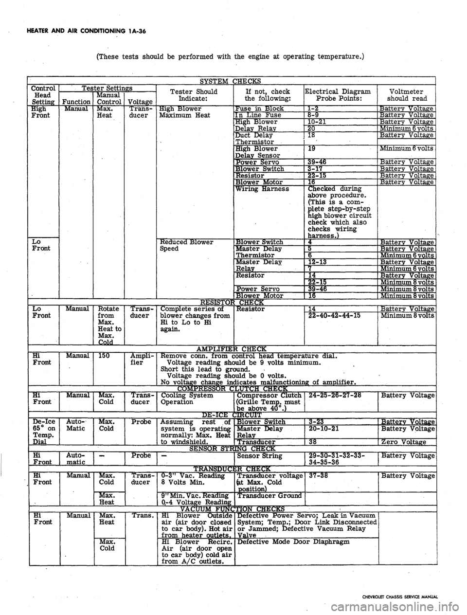
(These tests should be performed with the engine at operating temperature.)
SYSTEM CHECKS
Control
Head
Setting
High
Front
Lo
Front
Lo
Front
Hi
Front
Hi
Front
Tester Settings
Function
Manual
Manual
Manual
Manual
De-ice
65° on
Temp.
Dial
Hi
Front
Hi
Front
Hi
Front
Auto-
Matic
1 1
Auto-
matic
Manual
Manual
Manual
Control
Max.
Heat
Rotate
from
Max.
Heat to
Max.
Cold
150
Max.
Cold
Max.
Cold
Max.
Cold
Max.
Heat
Max.
Heat
Max.
Cold
Voltage
Trans-
ducer
Trans-
ducer
Ampli-
fier
Trans-
ducer
Probe
Probe
Trans-
ducer
Trans.
Tester Should
Indicate:
High Blower
Maximum Heat
Reduced Blower
Speed
Complete series of
blower changes from
Hi to Lo to Hi
again.
AMPLIFIE:
Remove conn, from c
Voltage reading she
Short this lead to grc
Voltage reading she
No voltage change in<
COMPRESSOR C
Cooling System
Operation
DE-ICE i
Assuming rest of
system is operating
normally: Max. Heat
1
to windshield.
SENSOR STR
•—
TRAtfSDtfC
0-3"
Vac. Reading
8 Volts Min.
9"
Min.
Vac.
Reading
0-4 Voltage Reading
If not, check
the following:
Fuse in Slock
In Line Fuse
High Blower
Delay Relay
Duct Delay
Thermistor
High Blower
Delay Sensor
Power Servo
Blower Switch
Resistor
Blower Motor
Wiring Harness
Blower Switch
Master Delay
Thermistor
Master Delay
Relay
Resistor
Power Servo
Blower Motor
CHECK
Resistor
I CHECK
Electrical Diagram
Probe Points:
1-2
8-9
10-21
20
18
19
*
9-46
-r
^2-3
15
16
Checked during
above procedure.
(This is a com-
plete step-by-step
high blower circuit
check which also
checks wiring
harness.)
4
5
6
L2-13
L4
""§2-15
39-46
1
16 1
14
22-40-42-44-15
.ontrol head temperature dial.
>uld be 9 volts minimum,
jund.
>uld be 0 volts,
iicates malfunctioning of amplifier.
JUTCJH CHUCK
Compressor Clutch
(Grille Temp, must
be above 40°.)
IRCUIT
Blower Switch
Master Delay
Relay
Transd
NGCl
ucer
Sensor String
2R CHECK
Transducer voltage
&t Max. Cold
position)
Transducer Ground
Hi Blower Outside
air (air door closed
to car body). Hot air
from heater outlets.
Hi Blower Recirc.
Air (air door open
to car body) cold air
from A/C outlets.
24-25-26-27-28
Voltmete
should re
ad
Battery Voltage
Battery Voltage
Battery Voltage
. Vtinimum
6
volts
Battery Voltage
Minimum
6
volts
Battery Vo]
Batterv Vo]
Ltage
Ltage
Battery Voltage
Batterv Voltage
3a
Bai
:terv Vo
tterv Vo
tage
tage
Minimum
6
volts
Batterv Voltage
Minimum
6
volts
Battery Voltage
Minimum
8
volts
Minimum 8 volts
Minimum 8 volts
Batterv Voltage
Minimum 8 volts
1 III • II »ll. —..• —•— . !!•• 1
Battery Voltage
3-23
20-10-21
38
29-30-31-32-33-
34-35-36
37-38
Defective Power Servo; Leak in Vacuum
System; Temp.; Door Link Disconnected
or Jammed; Defective Vacuum Relay
Valve
Defective Mode Door Diaphragm
Batterv Voltage
Battery Voltage
Zero Voltage
Battery Voltage
Battery Voltage
CHEVROLET CHASSIS SERVICE MANUAL
Page 60 of 659
HEATER AND AIR CONDITIONING 1A-37
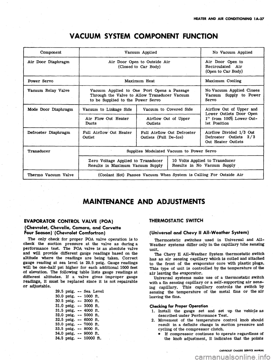
VACUUM SYSTEM COMPONENT FUNCTION
Component
Air Door Diaphragm
Power Servo
Vacuum Relay Valve
Mode Door Diaphragm
Defroster Diaphragm
Transducer
Thermo Vacuum Valve
Vacuum Applied
Air Door Open to Outside Air
(Closed to Car Body)
Maximum Heat
Vacuum Applied to One Port Opens a Passage
Through the Valve to Allow Transducer Vacuum
to be Supplied to the Power Servo
Vacuum to Linkage Side
Air Flow Out Heater
Ducts
Full Airflow Out Heater
Outlet
Vacuum to Covered Side
Airflow Out of Upper
Outlets
Full Airflow Out Defroster
Outlets (Full De-ice)
No Vacuum Applied
Air Door Open to
Re circulated Air
(Open to Car Body)
Maximum Cooling
No Vacuum Applied Closes
Vacuum Supply to Power
Servo
Airflow Out of Upper and
Lower Outlets Door Open
1"
from 100% Lower Out-
let Position
Airflow Divided 1/3 Out
Defroster Outlets 2/3
Out Heater Outlets
Supplies Modulated Vacuum to Power Servo
Zero Voltage Applied to Transducer
Results in Maximum Vacuum Supply
10 Volts Applied to Transducer
Results in No Vacuum Supply
(Coolant Hot) Passes Vacuum When System is Calling For Outside Air
MAINTENANCE AND ADJUSTMENTS
EVAPORATOR CONTROL VALVE (POA)
(Chevrolet, Chevelle, Comoro, and Corvette
Four Season) (Chevrolet Comfortron)
The only check for proper POA valve operation is to
check the suction pressure at the valve as during a
performance test. The POA valve is an absolute valve
and will provide different gauge readings based on the
altitude where the readings are being taken. Correct
gauge reading at sea level is 29.5 psig. Gauge readings
will be one-half psi higher for each additional 1000 feet
of elevation. The following table lists gauge readings at
different altitudes. If a valve gives improper gauge
readings, it must be replaced since it is not repairable
or adjustable.
29.5
30.0
30.5
31.0
31.5
32.0
32.5
33.0
33.5
34.0
34.5
psig.
psig.
psig.
psig.
psig.
psig.
psig.
psig.
psig.
psig.
psig.
— Sea 1
— 1000
— 2000
— 3000
— 4000
— 5000
— 6000
— 7000
— 8000
— 9000
Level
ft.
ft.
ft.
ft.
ft.
ft.
ft.
ft.
ft.
— 10000 ft.
THERMOSTATIC SWITCH
(Universal and Chevy II All-Weather System)
Thermostatic switches used in Universal and All-
Weather systems differ only in the capillary tube sensing
unit.
The Chevy n All-Weather System thermostatic switch
has an air sensing capillary which is coiled and attached
to the front of the evaporator core with plastic plugs.
This type of unit is controlled by the temperature of the
air leaving the evaporator.
Universal systems make use of a thermostatic switch
with a fin sensing capillary or a self-supporting air sens-
ing capillary. This capillary controls the switch by
sensing the temperature of the metal fins or the air
leaving the fins.
Checking for Proper Operation
1.
Install the gauge set and set up the vehicle as
described under Performance Test.
2.
Movement of the temperature control knob should
result in a definite change in suction pressure and
cycling of the compressor clutch.
• If compressor continues to operate regardless of
the knob adjustment, it indicates that the points
CHEVROLET CHASSIS SERVICE MANUAL
Page 61 of 659

HEATER AND AIR CONDITIONING 1A-38
HIGH BLOWER
DELAY RELAY
O) MASTER AND
HIGH BLOWER
DELAY RELAY
GROUND
Fig.
49A-Comfortron Wiring Diagram-Underhood
CHEVROLET CHASSIS SERVICE AAANUAL
Page 63 of 659
HEATER AND AIR CONDITIONING 1A-40
THERAAAL VACUUM
VALVE
TO ENGINE
VACUUM
SOURCE
VACUUM STORAGE
TANK
OUTSIDE AIR
DIAPHRAGM
MODE
DIAPHRAGM
VACUUM
RELAY
BLACK
DEFOG-DEICE
DIAPHRAGM
GREEN
BLACKj ||
|
BROWN
CONTROL
VALVE
Fig.
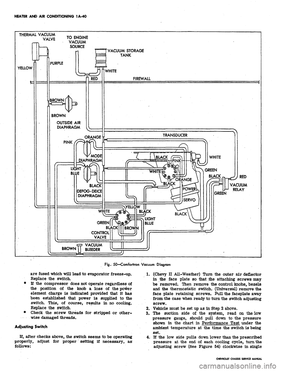
50—Comfortron Vacuum Diagram
are fused which will lead to evaporator freeze-up.
Replace the switch.
• If the compressor does not operate regardless of
the position of the knob a loss of the power
element charge is indicated provided that it has
been established that power is supplied to the
switch. This, of course, results in no cooling.
Replace the switch.
• Check the screw threads for stripped or other-
wise damaged threads.
Adjusting Switch
H, after checks above, the switch seems to be operating
properly,
follows:
adjust for proper setting if necessary, as
1.
(Chevy II All-Weather) Turn the outer air deflector
in the face plate so that the attaching screws may
be removed; Then remove the control knobs, bezels
and the thermostatic switch. (Universal) remove the
face plate retaining screws. Pull the faceplate away
from the case when ready to turn the switch adjusting
screw.
2.
Vehicle must be set up as in Step 2 above.
3.
The suction side of the system, read on the low
pressure gauge, should pull down to the pressure
shown in the chart in Performance Test under the
ambient temperature at the time the switch is being
set.
4.
If the low side pulls down lower than the prescribed
pressure at the end of each cooling cycle, turn the
adjusting screw (See Figure 54) clockwise in single
CHEVROLET CHASSIS SERVICE MANUAL
Page 80 of 659
HEATER AND AIR CONDITIONING 1A-57
EVAPORATOR PIPES
DISTRIBUTOR RELAY GRD.
ASSEMBLY & WASHER
EVAPORATOR ASM.
BLOWER
SHROUD
(RACKET
(PART OF
BLOWER)
Fig.
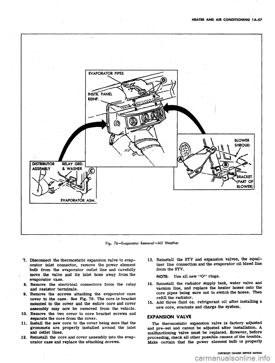
76—Evaporator Removal—All Weather
7. Disconnect the thermostatic expansion valve to evap-
orator inlet connector, remove the power element
bulb from the evaporator outlet line and carefully
move .the valve and its inlet hose away from the
evaporator case.
8. Remove the electrical connectors from the relay
and resistor terminals.
9. Remove the screws attaching the evaporator case
cover to the case. See Fig. 79. The core is bracket
mounted to the cover and the entire core and cover
assembly may now be removed from the vehicle.
10.
Remove the two cover to core bracket screws and
separate the core from the cover.
11.
Install the new core to the cover being sure that the
grommets are properly installed around the inlet
and outlet lines.
12.
Reinstall the core and cover assembly into the evap-
orator case and replace the attaching screws.
13.
Reinstall the STV and expansion valves, the equal-
izer line connection and the evaporator oil bleed line
from the STV.
NOTE:
Use all new «O" rings.
14.
Reinstall the radiator supply tank, water valve and
vacuum line, and replace the heater hoses onto the
core pipes being sure not to switch the hoses. Then
refill the radiator.
15.
Add three fluid oz. refrigerant oil after installing a
new core, evacuate and charge the system.
EXPANSION VALVE
The thermostatic expansion valve is factory adjusted
and pre-set and cannot be adjusted after installation. A
malfunctioning valve must be replaced. However, before
proceeding, check all other possible causes of the trouble.
Make certain that the power element bulb is properly
CHEVROLET CHASSIS SERVICE MANUAL
Page 85 of 659
HEATER AND AIR CONDITIONING 1A-62
2.
Insert the evaporator assembly into the outlet case
half and mount the evaporator, thermostatic switch,
and cable to the case.
3.
Install the face plate to the case and install control
retaining nuts and knobs.
4.
Assemble the case halves and mount the evaporator
pipe clamp.
5. Install the evaporator assembly as previously
described under EVAPORATOR.
BLOWER ASSEMBLY
Four-Season System
Chevrolet and Camaro
Removal
1.
Disconnect battery ground cable.
2.
Remove the right front fender and skirt assembly.
3.
Disconnect the motor wire at the flange connector.
4.
Disconnect the rubber air cooling tube from the
motor.
5. Remove the motor to case attaching screws and re-
move the blower assembly. If the sealer acts as an
adhesive, pry the assembly carefully away from the
6. Remove the blower from the motor shaft.
Fig.
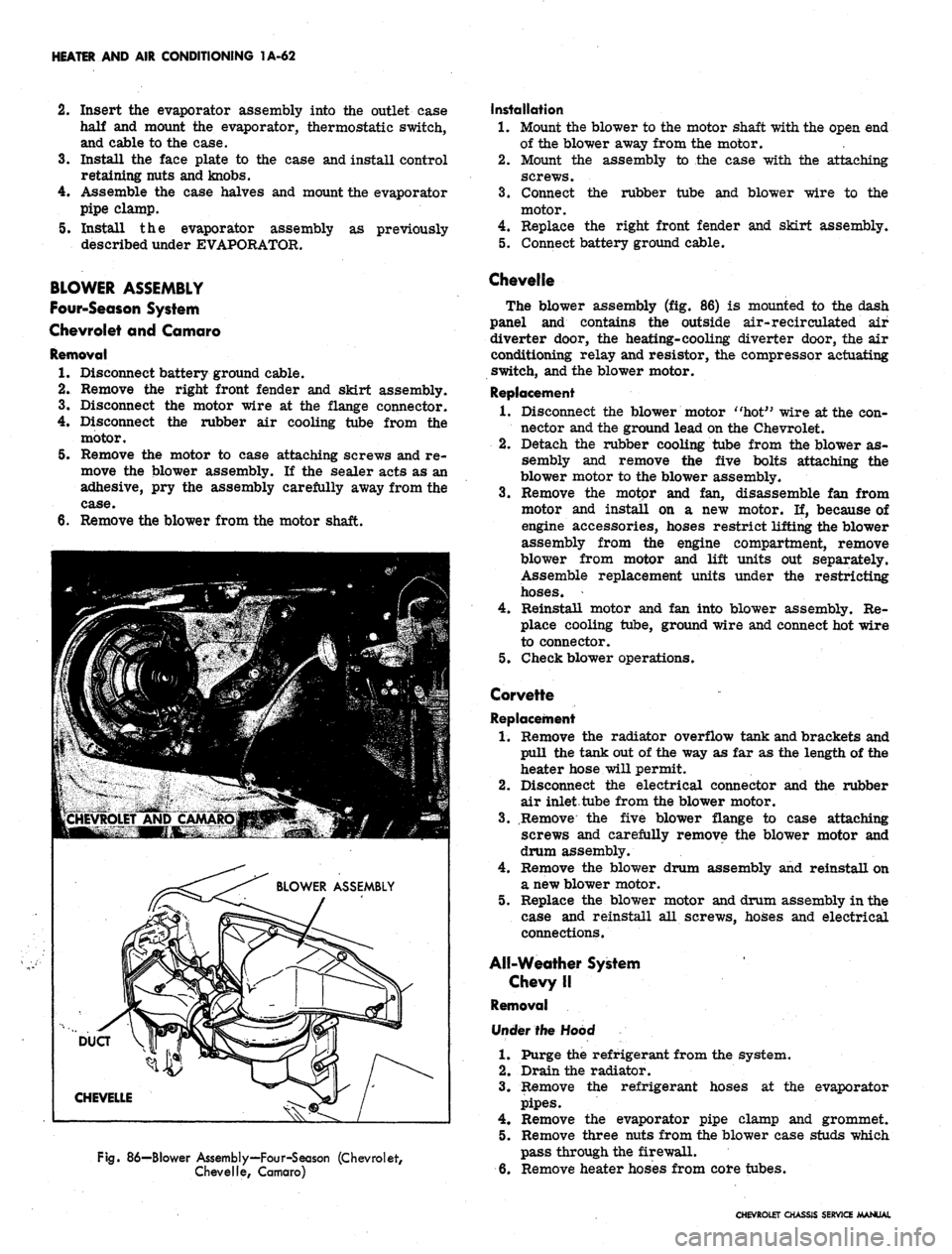
86—Blower Assembly—Four-Season (Chevrolet,
Chevelle, Camaro)
Installation
1.
Mount the blower to the motor shaft with the open end
of the blower away from the motor.
2.
Mount the assembly to the case with the attaching
screws.
3.
Connect the rubber tube and blower wire to the
motor.
4.
Replace the right front fender and skirt assembly.
5. Connect battery ground cable.
Chevelle
The blower assembly (fig. 86) is mounted to the dash
panel and contains the outside air-recirculated air
diverter door, the heating-cooling diverter door, the air
conditioning relay and resistor, the compressor actuating
switch, and the blower motor.
Replacement
1.
Disconnect the blower motor "hot" wire at the con-
nector and the ground lead on the Chevrolet.
2.
Detach the rubber cooling tube from the blower as-
sembly and remove the five bolts attaching the
blower motor to the blower assembly.
3.
Remove the motor and fan, disassemble fan from
motor and install on a new motor. If, because of
engine accessories, hoses restrict lifting the blower
assembly from the engine compartment, remove
blower from motor and lift units out separately.
Assemble replacement units under the restricting
hoses.
4.
Reinstall motor and fan into blower assembly. Re-
place cooling tube, ground wire and connect hot wire
to connector.
5. Check blower operations.
Corvette
Replacement
1.
Remove the radiator overflow tank and brackets and
pull the tank out of the way as far as the length of the
heater hose will permit.
2.
Disconnect the electrical connector and the rubber
air inlet tube from the blower motor.
3.
Remove the five blower flange to case attaching
screws and carefully remove the blower motor and
drum assembly.
4.
Remove the blower drum assembly and reinstall on
a new blower motor.
5. Replace the blower motor and drum assembly in the
case and reinstall all screws, hoses and electrical
connections.
All-Weather System
Chevy II
Removal
Under the Hood
1.
Purge the refrigerant from the system.
2.
Drain the radiator.
3.
Remove the refrigerant hoses at the evaporator
pipes.
4.
Remove the evaporator pipe clamp and grommet.
5. Remove three nuts from the blower case studs which
pass through the firewall.
6. Remove heater hoses from core tubes.
CHEVROLET CHASSIS SERVICE MANUAL
Page 91 of 659
HEATER AND AIR CONDITIONING 1A-68
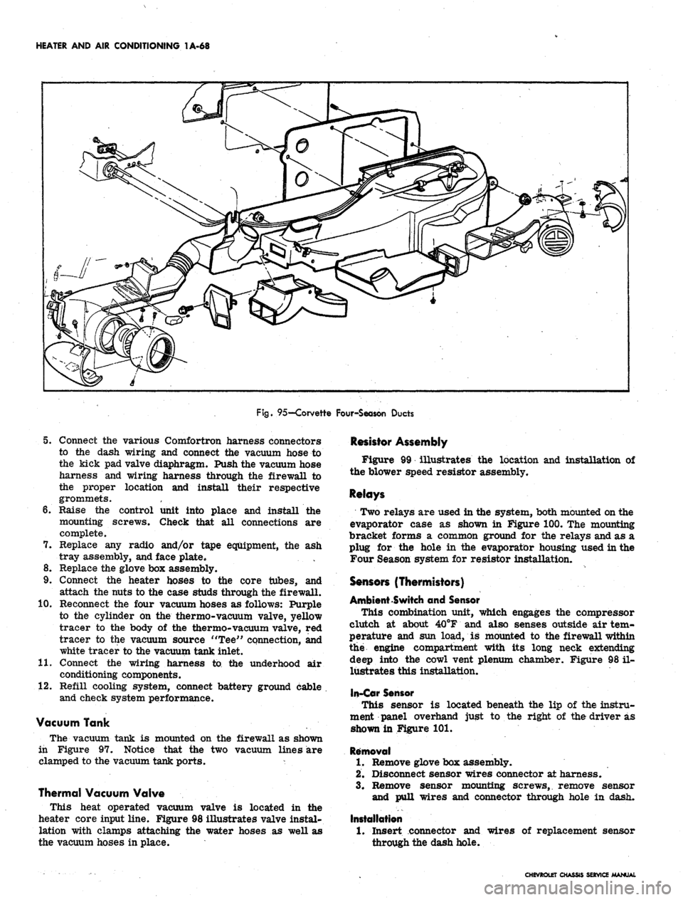
Fig.
95—Corvette Four-Season Ducts
5. Connect the various Comfortron harness connectors
to the dash wiring and connect the vacuum hose to
the kick pad valve diaphragm. Push the vacuum hose
harness and wiring harness through the firewall to
the proper location and install their respective
grommets.
6. Raise the control unit into place and install the
mounting screws. Check that all connections are
complete.
7. Replace any radio and/or tape equipment, the ash
tray assembly, and face plate.
8. Replace the glove box assembly.
9. Connect the heater hoses to the core tubes, and
attach the nuts to the case studs through the firewall.
10.
Reconnect the four vacuum hoses as follows: Purple
to the cylinder on the thermo-vacuum valve, yellow
tracer to the body of the thermo-vacuum valve, red
tracer to the vacuum source "Tee" connection, and
white tracer to the vacuum tank inlet.
11.
Connect the wiring harness to the underhood air
conditioning components.
12.
Refill cooling system, connect battery ground cable
and check system performance.
Vacuum Tank
The vacuum tank is mounted on the firewall as shown
in Figure 97. Notice that the two vacuum lines are
clamped to the vacuum tank ports. *
Thermal Vacuum Valve
This heat operated vacuum valve is located in the
heater core input line. Figure 98 illustrates valve instal-
lation with clamps attaching the water hoses as well as
the vacuum hoses in place.
Resistor Assembly
Figure 99 illustrates the location and installation of
the blower speed resistor assembly.
Relays
Two relays are used in the system, both mounted on the
evaporator case as shown in Figure 100. The mounting
bracket forms a common ground for the relays and as a
plug for the hole in the evaporator housing used in the
Four Season system for resistor installation.
Sensors (Thermistors)
Ambient Switch and Sensor
This combination unit, which engages the compressor
clutch at about 40°F and also senses outside air tem-
perature and sun load, is mounted to the firewall within
the engine compartment with its long neck extending
deep into the cowl vent plenum chamber. Figure 98 il-
lustrates this installation,
In-Car Sensor
This sensor is located beneath the lip of the instru-
ment panel overhand just to the right of the driver as
shown in Figure 101.
Removal
1.
Remove glove box assembly.
2.
Disconnect sensor wires connector at harness.
3.
Remove sensor mounting screws, remove sensor
and pull wires and connector through hole in dash.
Installation
1.
Insert connector and
through the dash hole.
wires of replacement sensor
CHEVROLET CHASSIS SERVICE MANUAL