ignition CHEVROLET CAMARO 1967 1.G Chassis Owner's Manual
[x] Cancel search | Manufacturer: CHEVROLET, Model Year: 1967, Model line: CAMARO, Model: CHEVROLET CAMARO 1967 1.GPages: 659, PDF Size: 114.24 MB
Page 335 of 659
ENGINE-ELECTRICAL 6Y-10
circuit. Make absolutely certain all connections in
the circuit are secure.
5.
Do not short across or ground any of the terminals
on the generator or regulator.
6. Do not attempt to polarize the generator.
7.
Do not disconnect lead at generator without first dis-
connecting battery ground cable.
Trouble in the A.C. charging system will usually be
indicated by one or more of the following conditions:
1.
Faulty indicator lamp or ammeter operation.
2.
An undercharged battery (usually evidenced by slow
cranking speeds).
3.
An overcharged battery (usually evidenced by exces-
sive battery water usage).
4.
Excessive generator noise or vibration.
Described below are a series of on-the-vehicle quick
checks which are designed to assist the service tech-
nician in locating troubles within the various components
of the engine electrical system. Additional checks, ad-
justments and overhaul procedures of these components
are also described in the "Charging Systems—Service
Operations Section" and should be referred to as
necessary.
STATIC CHECKS
Before making any electrical checks, perform the fol-
lowing static checks:
1.
Check for loose fan belt.
2.
Check for defective battery. (Refer to Battery).
3.
Inspect all connections, including the slip-on con-
nectors at the regulator and Delcotron.
NOTE: Do not short field to ground to check if
generator is charging since this will seriously
damage the charging system.
SYSTEM CONDITION TEST
This test is used .to indicate the overall condition of the
charging system (both good and defective) and to isolate
the malfunctioning unit if the system is defective.
NOTE: On Corvette models difficulty may be
encountered -when attempting to make the re-
quired test connections at the voltage regulator.
It is advisable to remove the regulator from its
mounting location to perform the necessary con-
nections at the regulator for the following tests
but make sure unit is grounded.
1.
With ignition off, perform the prescribed Static
Checks outlined in this section. Then set hand brake
and shift transmission
into
neutral.
2.
Connect a voltmeter from junction block relay to
ground at regulator base.
CAUTION: Be sure meter clip does not touch a
resistor or terminal extension under regulator,
3.
Connect a tachometer on engine.
4.
Models equipped with Indicator Lamp: Turn ignition
switch on "ON" position and check indicator lamp.
If lamp fails to glow, perform appropriate tests and
corrections (Indicator Lamp Circuit Tests) before
continuing.
Models equipped with Ammeter: Turn ignition
switch to "ACC" with an accessory on and check
ammeter. If ammeter fails to read discharge, check
ammeter circuit before continuing.
5.
Models equipped with Indicator Lamp: If lamp glows,
start the engine and run' it at 1500 rpm or above.
Check indicator lamp. If lamp fails to go out, per-
form appropriate test and corrections (Indicator
Lamp Circuit Test) before continuing.
Models equipped with Ammeter: If ammeter reads
discharge, start the engine and observe ammeter. If
meter fails to move toward charge (from original
position), perform appropriate test and corrections
(Field Circuit Tests) before continuing.
NOTE: At this point a field circuit has been
established and any other problem will lie in
generator or regulator.
6. Turn on high-beam headlights and heater blower
motor to high speed, run engine at or above 1500
rpm (for a few minutes, if necessary) and read the
voltage on meter.
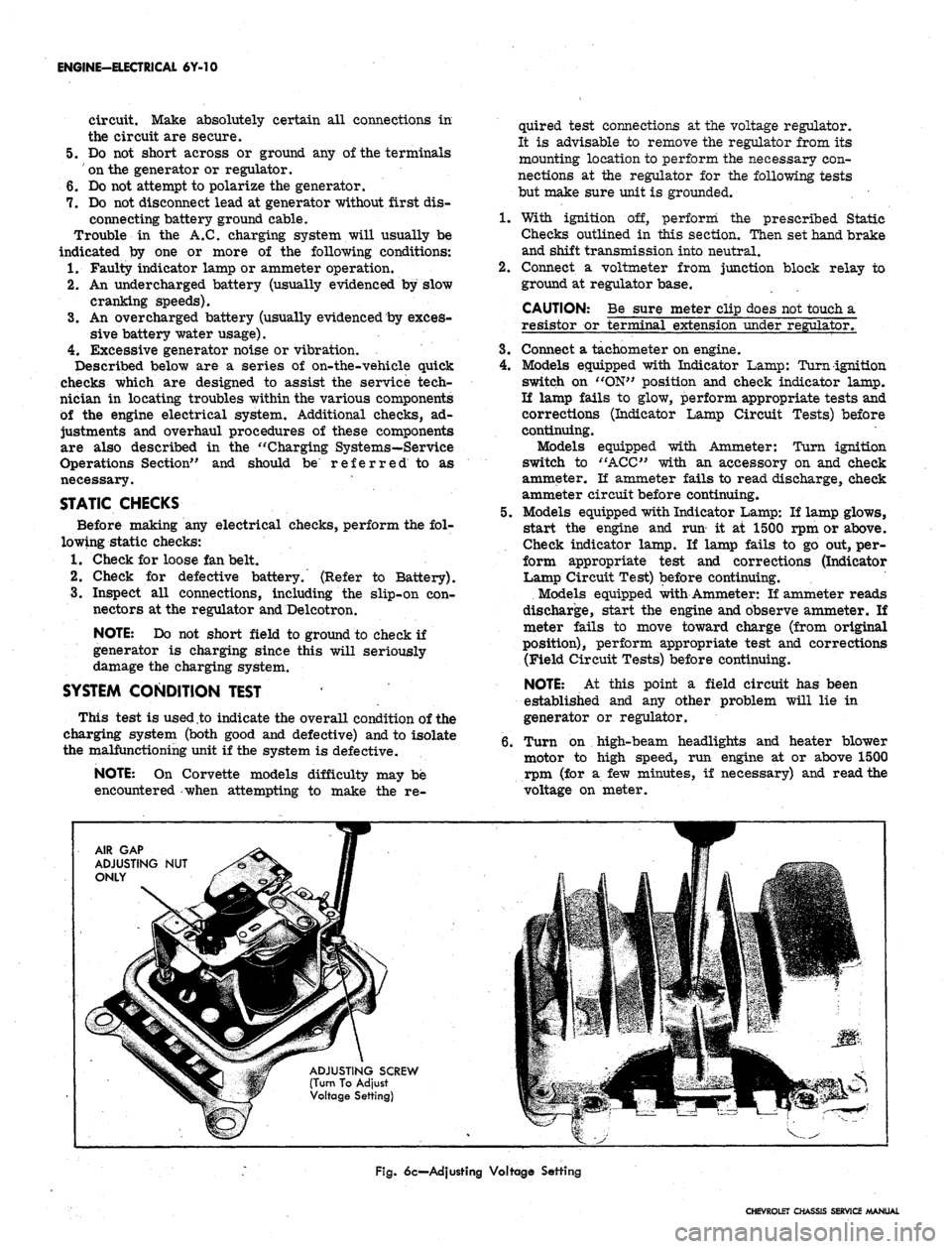
AIR GAP
ADJUSTING NUT
ONLY
ADJUSTING SCREW
(Turn To Adjust
Voltage Setting)
Fig.
6c—Adjusting Voltage Setting
CHEVROLET CHASSIS SERVICE MANUAL
Page 337 of 659

ENGINE-ELECTRICAL 6Y-J2
Fig.
8c—Ammeter Method Test Connections
10.
Turn off ignition, disconnect battery ground cable,
and remove all test equipment.
11.
li the Delcotron meets the test specifications, the
problem is not in the generator.
12.
Ti the Delcotron fails to meet the test specifications,
remove it and perform bench tests and make repair
needed.
DELCOTRON DIODE AND FIELD TEST (Fig. 9c)
NOTE:
These tests will indicate good,, shorted
or open field or shorted diode but will not indi-
cate a failed open diode. If output was low and
following tests show good, refer to service op-
erations to determine cause and repair.
1.
Disconnect battery ground cable at battery.
2.
Positive diodes (Test A) connect an ohmmeter be-
tween "R" terminal and "BAT" terminal and note
Fig.
9c-Deicotron Diode and Field Test
reading, then reverse the leads at same terminals
and note this reading. Meter should read high re-
sistance in one direction and low in the other.
3.
Negative diodes (Test B) connect ohmmeter between
"R" terminal and "GRD" and note reading, then
reverse the leads and note this reading. Meter
should read high in one direction and low in the
other.
NOTE:
A high or low reading in both directions
indicates a defective diode.
4.
Open Field Check:
a. Connect an ohmmeter from "F" terminal to
"GRD"
terminal stud and note reading on the
lowest range scale. Meter should read 7 to
20 ohms.
b.
If meter reads zero or excessively high resist-
ance, the Delcotron is faulty.
5. If above tests indicate a defective Delcotron, remove
and completely check Delcotron as outlined under
''Service Operations".
INDICATOR LAMP/INITIAL FIELD
EXCITATION CIRCUIT TESTS (Fig. 10c)
On standard models the indicator lamp circuit provides
initial field excitation (causing lamp to glow). The light
is cancelled by closing the field relay which applies bat-
tery voltage to both sides of bulb (bulb goes out).
The indicator light should glow when ignition switch is
"ON"
and go out almost immediately when engine starts.
Ammeter equipped vehicles use the same initial field
excitation and control circuits as the indicator lamp ex-
cept the lamp is omitted. The continuity tests on both
type vehicles can be made as follows:
If Lamp Fails to Glow or Ammeter Fails to
Function the Possible Causes are:
1.
Faulty bulb or bulb socket.
2.
Faulty ammeter.
3.
An open circuit in wiring, regulator, or field.
4.
A shorted positive diode—(may also cause glow with
ignition switch "OFF").
TEST AS FOLLOWS:
1.
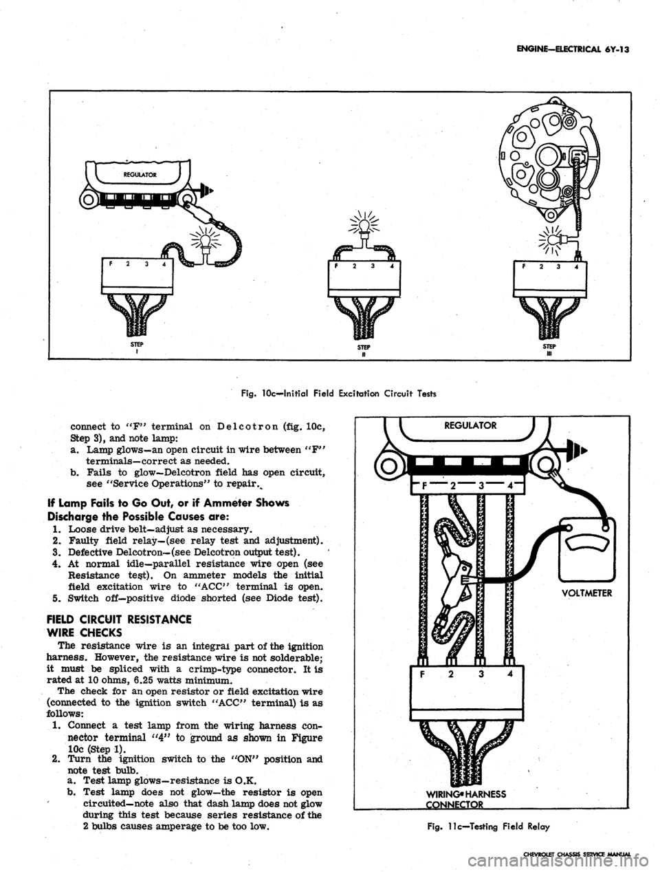
Disconnect connector from regulator and turn
ignition switch to "ON". Connect a test lamp from
connector terminal "4" to ground (fig. 10c, Step 1)
and note test lamp.
a. Lamp fails to glow—check for faulty bulb, socket
or open circuit between switch and regulator con-
nector. Repair as needed.
b.
Light goes on—failure is in regulator, Delcotron,
or wire between "F" terminals on regulator and
Delcotron. Go to Step 2.
2.
Disconnect lamp lead at ground end and connect be-
tween connector "F" and "4" terminals (fig. 10c,
Step 2), and note lamp:
a. Test Lamp glows—problem is in regulator. An
open circuit in regulator or relay is stuck dosed.
See "Service Operations" for repair.
b.
Fails to glow—problem is in wire between "F"
terminals on generator and regulator or infield
windings. Go to Step 3.
3.
Disconnect test lamp at connector "F" terminal and
CHEVROLET CHASSIS SERVICE MANUAL
Page 338 of 659
ENGINE-ELECTRICAL 6Y-13
F 2 3 4
f 2 3 4
F 2 3 4
Fig.
10c—Initial Field Excitation Circuit Tests
connect to "F" terminal on Delcotron (fig. 10c,
Step 3), and note lamp:
a. Lamp glows-an open circuit in wire between "F"
terminals—correct as needed.
b.
Fails to glow—Delcotron field has open circuit,
see "Service Operations" to repair %
If Lamp Fails to Go Out, or if Ammeter Shows
Discharge the Possible Causes are:
1.
Loose drive belt—adjust as necessary.
2.
Faulty field relay—(see relay test and adjustment).
3.
Defective Delcotron—(see Delcotron output test).
4.
At normal idle—parallel resistance wire open (see
Resistance test). On ammeter models the initial
field excitation wire to "ACC" terminal is open.
5. Switch off—positive diode shorted (see Diode test).
FIELD CIRCUIT RESISTANCE
WIRE CHECKS
The resistance wire is an integral part of the ignition
harness. However, the resistance wire is not solderable;
it must be spliced with a crimp-type connector. It is
rated at 10 ohms, 6.25 watts minimum.
The check for an open resistor or field excitation wire
(connected to the ignition switch "ACC" terminal) is as
follows:
1.
Connect a test lamp from the wiring harness con-
nector terminal "4" to ground as shown in Figure
10c (Step 1).
2.
Turn the ignition switch to the "ON" position and
note test bulb.
a. Test lamp glows—resistance is O.K.
b.
Test lamp does not glow—the resistor is open
circuited—note also that dash lamp does not glow
during this test because series resistance of the
2 bulbs causes amperage to be too low.
VOLTMETER
3 4
WIRING*
HARNESS
CONNECTOR
Fig.
11c—Testing Field Relay
CHEVROLET CHASSIS SERVICE MANUAL
Page 339 of 659
ENGINE-ELECTRICAL 6Y-14
VOLTMETER
WIRING HARNESS
CONNECTOR
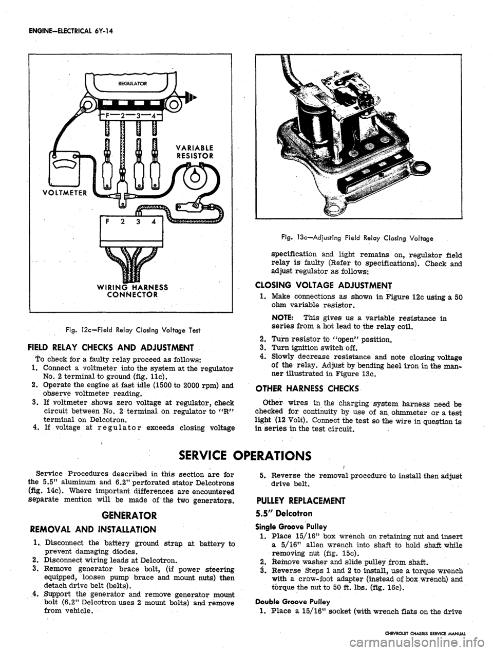
Fig.
12c—Field Relay Closing Voltage Test
FIELD RELAY CHECKS AND ADJUSTMENT
To check for a faulty relay proceed as follows:
1.
Connect a voltmeter into the system at the regulator
No.
2 terminal to ground (fig. lie).
2.
Operate the engine at fast idle (1500 to 2000 rpm) and
observe voltmeter reading.
3.
If voltmeter shows zero voltage at regulator, check
circuit between No. 2 terminal on regulator to "R"
terminal on Delcotron.
4.
If voltage at regulator exceeds closing voltage
Fig.
13c—Adjusting Field Relay Closing Voltage
specification and light remains on, regulator field
relay is faulty (Refer to specifications). Check and
adjust regulator as follows:
CLOSING VOLTAGE ADJUSTMENT
•1.
Make connections as shown in Figure 12c using a 50
ohm variable resistor.
NOTE: This gives us a variable resistance in
series from a hot lead to the relay coil.
2.
Turn resistor to "open" position.
3.
Turn ignition switch off.
4.
Slowly decrease resistance and note closing voltage
of the relay. Adjust by bending heel iron in the man-
ner illustrated in Figure 13c.
OTHER HARNESS CHECKS
Other wires in the charging system harness need be
checked for continuity by use of an ohmmeter or a test
ligjit (12 Volt). Connect the test so the wire in question is
in series in the test circuit.
SERVICE OPERATIONS
Service Procedures described in this section are for
the 5.5" aluminum and 6.2" perforated stator Delcotrons
(fig. 14c). Where important differences are encountered
separate mention will be made of the two generators.
GENERATOR
REMOVAL AND INSTALLATION
1.
Disconnect the battery ground strap at battery to
prevent damaging diodes.
2.
Disconnect wiring leads at Delcotron.
3.
Remove generator brace bolt, (if power steering
equipped, loosen pump brace and mount nuts) then
detach drive belt (belts).
4.
Support the generator and remove generator mount
bolt (6.2" Delcotron uses 2 mount bolts) and remove
from vehicle.
5.
Reverse the removal procedure to install then adjust
drive belt.
PULLEY REPLACEMENT
5.5" Delcotron
Single Groove Pulley
1.
Place 15/16" box wrench on retaining nut and insert
a 5/16" alien wrench into shaft to hold shaft while
removing nut (fig. 15c).
2.
Remove washer and slide pulley from shaft.
3.
Reverse Steps 1 and
2
to install, use a torque wrench
with a crow-foot adapter (instead of box wrench) and
torque the nut to 50 ft. lbs. (fig. 16c).
Double Groove Pulley
1.
Place a 15/16" socket (with wrench flats on the drive
CHEVROLET CHASSIS SERVICE MANUAL
Page 343 of 659
ENGINE-ELECTRICAL 6Y-18
IGNITION SYSTEMS
INDEX
Page
General Description . 6Y-18
Maintenance and Adjustments 6Y-19
Breaker Point System 6Y-19
Breakerless System . . 6Y-X9
Ignition Coil Check 6Y-19
Spark Plugs 6Y-19
Service Operations , 6Y-19
Distributor Contact Points . 6Y-19
Cleaning 6Y-19
Replacement 6Y-20
Setting Dwell Angle 6Y-21
Distributor Condenser 6Y-22
Performance Diagnosis. 6Y-22
Replacement . . 6Y-23
Distributor
Breaker Point Type 6Y-23
Removal. . 6Y-23
Disassembly • 6Y-23
Page
Cleaning and Inspection .....'.., 6Y-25
Assembly . 6Y-25
Installation 6Y-26
Breakerless i 6Y-27
Removal . 6Y-27
Disassembly and Assembly 6Y-27
Installation 6Y-27
Off-Engine Test. . 6Y-27
Coil Replacement 6Y-27
Pulse Amplifier. 6Y-28
Disassembly .6Y-4S8
Component Checks
!
6Y-28
Assembly 6Y-29
Ignition Switch Replacement 6Y-29
Spark Plugs 6Y-30
Cleaning and Regapping I ....... 6Y-30
Installation . 6Y-31
GENERAL DESCRIPTION
There are two ignition systems available on 1967
vehicles. The breaker point type which is continued as
the regular production system and the optional (Corvette
only) transistor controlled breakerless ignition system
(magnetic pulse type). The transistor ignition system
features a specially designed distributor, control unit
(ignition pulse amplifier), and a special coil. Two resist-
ance wires are also used in the circuit; one as a ballast
between the coil negative terminal and ground, while the
other resistance wire provides a voltage drop for the
engine run circuit and is by-passed at cranking. The
other units in the system (the ignition switch, spark
plugs,
and battery) are of standard design. The dis-
tributor and control unit (ignition pulse amplifier) are
shown in Figures li and 2i.
CAP-
VACUUM
PICK-UP
COIL LEADS
PICK-UP COIL
CONNECTOR BODY
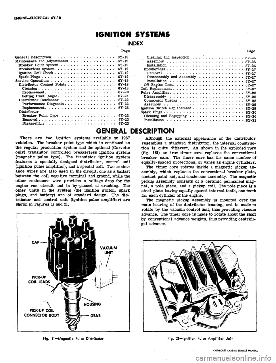
Although the external appearance of the distributor
resembles a standard distributor, the internal construc-
tion is quite different. As shown in the exploded view
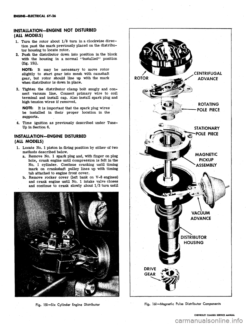
(fig. 16i) an iron timer core replaces the conventional
breaker cam. The timer core has the same number of
equally-spaced projections, or vanes as engine cylinders.
The timer core rotates inside a magnetic pickup as-
sembly, which replaces the conventional breaker plate,
contact point set, and condenser assembly. The magnetic
pickup assembly consists of a ceramic permanent mag-
net, a pole piece, and a pickup coil. The pole piece
is.
a
steel plate having equally spaced internal teeth, one tooth
for each cylinder of the engine.
The magnetic pickup assembly is mounted over the
main bearing of the distributor housing, and is made to
rotate by the vacuum control unit, thus providing vacuum
advance. The timer core is made to rotate about the shaft
by conventional advance weights, thus providing centrifu-
gal advance.
Fig.
li—
Magnetic Pulse Distributor
Fig.
2i-lgnition Pulse Amplifier Unit
CHEVROLET CHASSIS SERVICE MANUAL
Page 344 of 659
MAINTENANCE AND ADJUSTMENTS
ENGINE-ELECTRICAL 6Y-19
PERIODIC MAINTENANCE
BREAKER POINT SYSTEM
The distributor breaker points and spark plugs are the
only ignition system components that require periodic
service. The remainder of the ignition system requires
only periodic inspection to check operation of the units,
tightness of the electrical connections, and condition of
the wiring. When checking the coil, test with a reputable
tester.
Breaker type distributors are equipped with cam lubri-
cator and should have the wick replaced at the same time
contact point set is replaced. It is not necessary to
lubricate the breaker cam when using a cam lubricator.
Do not attempt to lubricate the wick - Replace when
necessary. When installing a new wick, adjust its posi-
tion so the end of the wick just touches the lobe of the
breaker cam.
Distributor shaft lubrication is accomplished by a
reservoir of lube around the mainshaft in the distributor
body.
BREAKERLESS SYSTEM
Since there are no moving parts in the ignition pulse
amplifier unit mounted forward of the radiator bulkhead,
and the distributor shaft and bushings have permanent
type lubrication, no periodic maintenance is therefore
required for the breakerless ignition system. The dis-
tributor lower bushing is lubricated by engine oil through
a splash hole in the distributor housing, and a housing
cavity next to the upper bushing contains a supply of
lubricant which will last between overhaul periods. At
time of overhaul, the upper bushing may be lubricated
by removing the plastic seal and then adding SAE 20 oil
to the packing in the cavity. A new plastic seal will be
required since the old one will be damaged during
removal.
Tachometer readings for test purposes can be made on
the primary circuit of the breakerless ignition system in
the same manner as on the conventional ignition system,
however before attempting to connect a test tachometer
into the primary circuit check with your instrument
supplier to insure that satisfactory readings can be
obtained and the breakerless system will not be damaged
by the tachometer that is to be used,
IGNITION COIL CHECK (BREAKERLESS)
The ignition coil primary can be checked for an open
PULSE
AMPLIFIER
IGN. SWITCH WIRE
"("IGN" TERMINAL)
-E3 IJU
12
WHITE-
-20 BLACKf' • 12 WHITE-
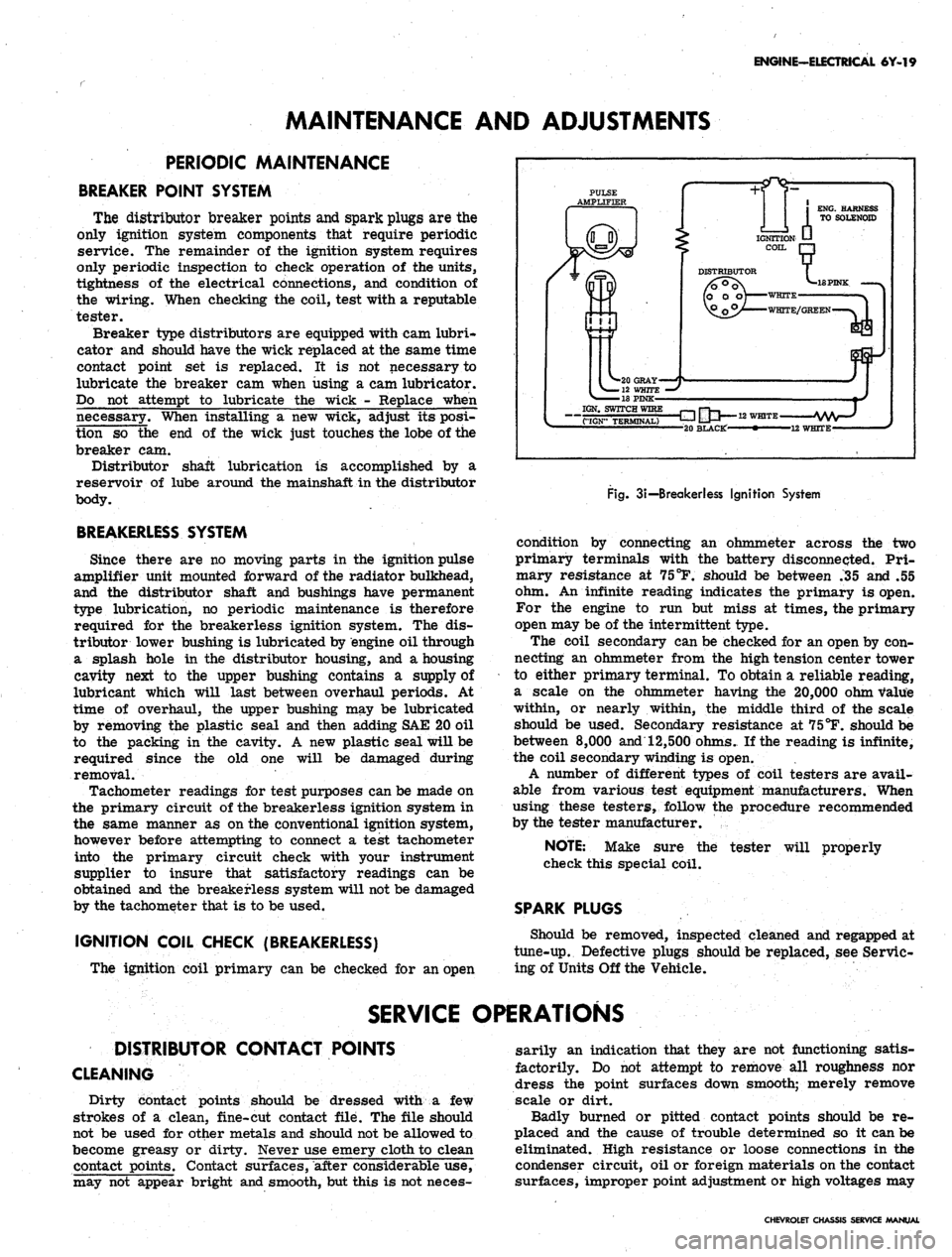
Fig.
3i—
Breakerless Ignition System
condition by connecting an ohmmeter across the two
primary terminals with the battery disconnected. Pri-
mary resistance at 75
°F.
should be between .35 and .55
ohm. An infinite reading indicates the primary is open.
For the engine to run but miss at times, the primary
open may be of the intermittent type.
The coil secondary can be checked for an open by con-
necting an ohmmeter from the high tension center tower
to either primary terminal. To obtain a reliable reading,
a scale on the ohmmeter having the 20,000 ohm value
within, or nearly within, the middle third of the scale
should be used. Secondary resistance at 75°F. should be
between
8,000
and 12,500 ohms. If the reading is infinite,
the coil secondary winding is open.
A number of different types of coil testers are avail-
able from various test equipment manufacturers. When
using these testers, follow the procedure recommended
by the tester manufacturer.
tester will properly
NOTE:
Make sure the
check this special coil.
SPARK PLUGS
Should be removed, inspected cleaned and regapped at
tune-up. Defective plugs should be replaced, see Servic-
ing of Units Off the Vehicle.
SERVICE OPERATIONS
DISTRIBUTOR CONTACT POINTS
CLEANING
Dirty contact points should be dressed with a few
strokes of a clean, fine-cut contact file. The file should
not be used for other metals and should not be allowed to
become greasy or dirty. Never use emery cloth to clean
contact points. Contact surfaces, after considerable use,
may not appear bright and smooth, but this is not neces-
sarily an indication that they are not functioning satis-
factorily. Do not attempt to remove all roughness nor
dress the point surfaces down smooth; merely remove
scale or dirt.
Badly burned or pitted contact points should be re-
placed and the cause of trouble determined so it can be
eliminated. High resistance or loose connections in the
condenser circuit, oil or foreign materials on the contact
surfaces, improper point adjustment or high voltages may
CHEVROLET CHASSIS SERVICE MANUAL
Page 345 of 659
ENGINE-ELECTRICAL 6Y-20
cause oxidized contact points. Check for these conditions
where burned contacts are experienced. An
out-of-
balance condition in the ignition system, often the result
of too much or too little condenser capacity, is indicated
where point pitting is encountered.
REPLACEMENT
Four and Six Cylinder Engine Distributor
1.
Release distributor cap hold-down screws, remove
cap and place it out of work area.
2.
Remove rotor.
3.
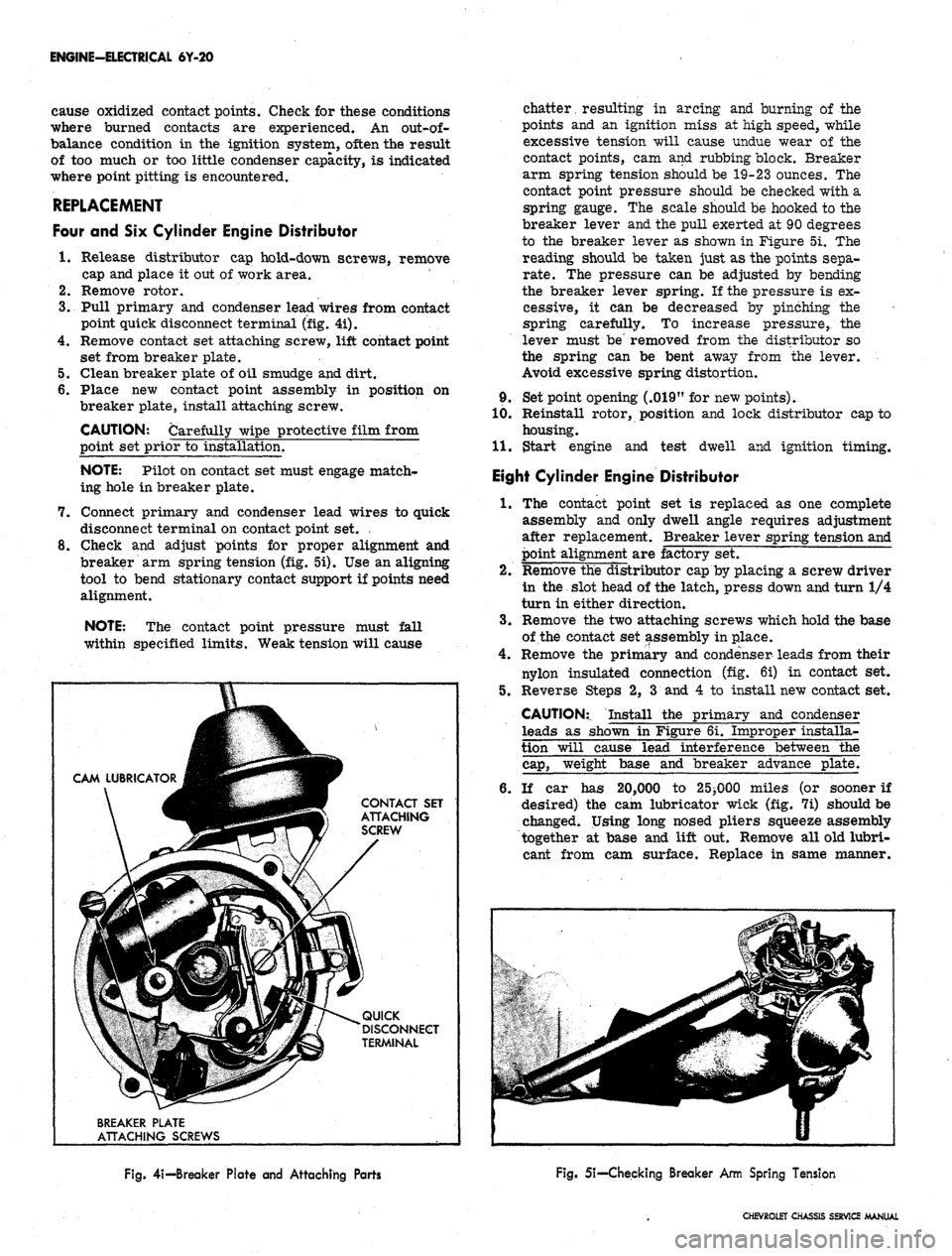
Pull primary and condenser lead wires from contact
point quick disconnect terminal (fig. 4i).
4.
Remove contact set attaching screw, lift contact point
set from breaker plate.
5.
Clean breaker plate of oil smudge and dirt.
6. Place new contact point assembly in position on
breaker plate, install attaching screw.
CAUTION: Carefully wipe protective film from
point set prior to installation.
NOTE: Pilot on contact set must engage match-
ing hole in breaker plate.
7.
Connect primary and condenser lead wires to quick
disconnect terminal on contact point set. .
8. Check and adjust points for proper alignment and
breaker arm spring tension (fig. 5i). Use an aligning
tool to bend stationary contact support if points need
alignment.
NOTE: The contact point pressure must fall
within specified limits. Weak tension will cause
CONTACT SET
ATTACHING
SCREW
QUICK
DISCONNECT
TERMINAL
BREAKER PLATE
ATTACHING SCREWS
chatter, resulting in arcing and burning of-the
points and an ignition miss at high speed, while
excessive tension will cause undue wear of the
contact points, cam and rubbing block. Breaker
arm spring tension should be 19-23 ounces. The
contact point pressure should be checked with a
spring gauge. The scale should be hooked to the
breaker lever and the pull exerted at 90 degrees
to the breaker lever as shown in Figure 5i. The
reading should be taken just as the points sepa-
rate.
The pressure can be adjusted by bending
the breaker lever spring. If the pressure is ex-
cessive, it can be decreased by pinching the
spring carefully. To increase pressure,, the
lever must be' removed from the distributor so
the spring can be bent away from the lever.
Avoid excessive spring distortion.
9. Set point opening (.019" for new points).
10.
Reinstall rotor, position and lock distributor cap to
housing.
11.
$tart engine and test dwell and ignition timing.
Eight Cylinder Engine Distributor
1.
The contact point set is replaced as one complete
assembly and only dwell angle requires adjustment
after replacement. Breaker lever spring tension and
point alignment are factory set.
2.
Remove the distributor cap by placing a screw driver
in the slot head of the latch, press down and turn 1/4
turn in either direction.
3.
Remove the two attaching screws which hold the base
of the contact set assembly in place.
4.
Remove the primary and condenser leads from their
nylon insulated connection (fig. 6i) in contact set.
5.
Reverse Steps 2, 3 and 4 to install new contact set.
CAUTION:. Install the primary and condenser
leads as shown in Figure 6i. Improper installa-
tion will cause lead interference between the
cap,
weight base and breaker advance plate.
6. If car has 20,000 to 25^000 miles (or sooner if
desired) the cam lubricator wick (fig. 7i) should be
changed. Using long nosed pliers squeeze assembly
together at base and lift out. Remove all old lubri-
cant from cam surface. Replace in same manner.
Fig.
4i—Breaker Plate and Attaching Parts
Fig. 5i—-Checking Breaker Arm Spring Tension
CHEVROLET CHASSIS SERVICE MANUAL
Page 346 of 659
ENGINE-ELECTRICAL
6Y-21
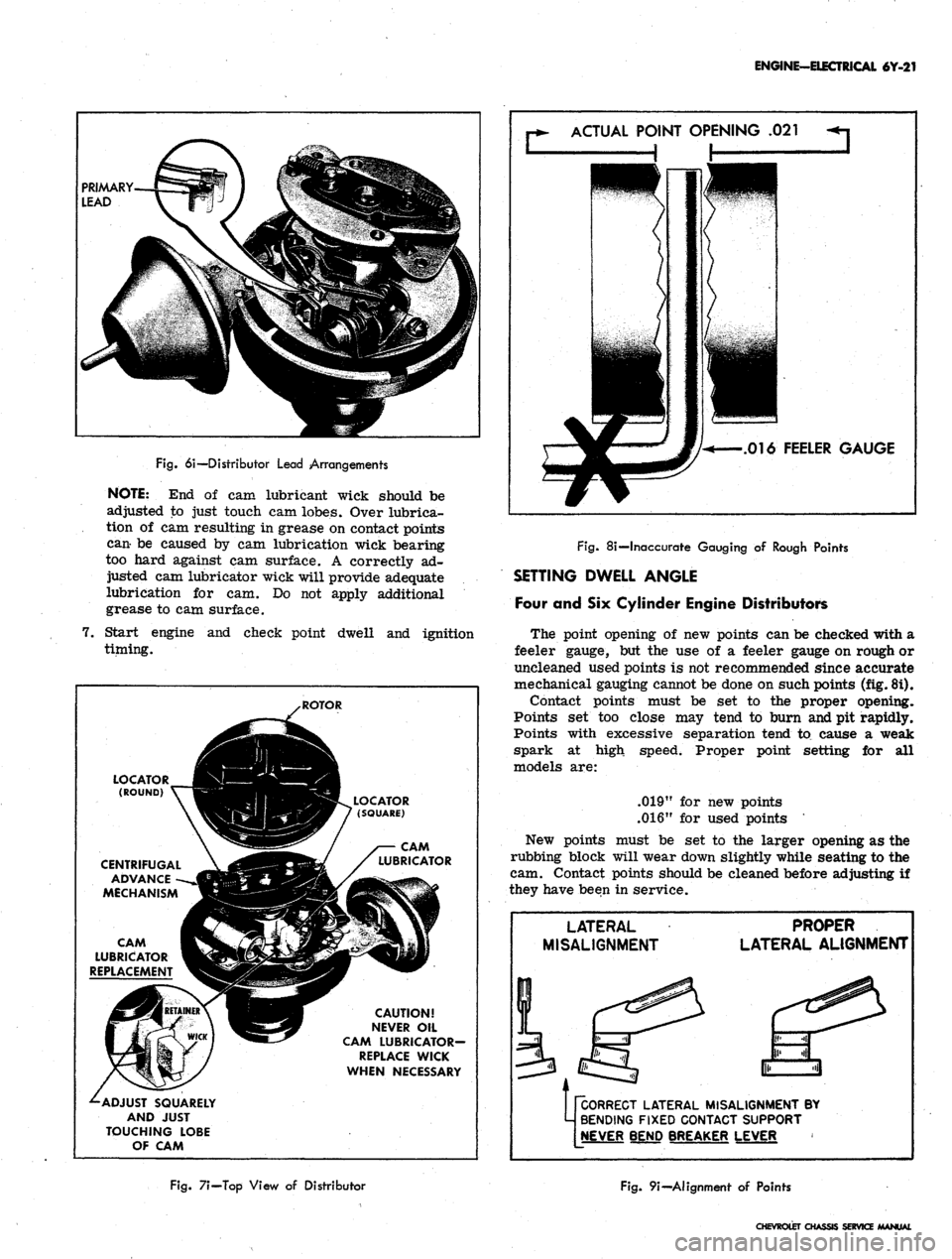
Fig.
6i—Distributor Lead Arrangements
NOTE:
End of cam
lubricant wick should
be
adjusted
to
just touch
cam
lobes. Over lubrica-
tion
of cam
resulting
in
grease
on
contact points
can-
be
caused
by cam
lubrication wick bearing
too hard against
cam
surface.
A
correctly
ad-
justed
cam
lubricator wick will provide adequate
lubrication
for cam. Do not
apply additional
grease
to cam
surface.
7.
Start engine
and
check point dwell
and
ignition
timing.
ACTUAL
POINT OPENING
.021
.016
FEELER GAUGE
LOCATOR ___JH^H
(ROUND)
V~^3H|
CENTRIFUGAL
\
jdft
ADVANCE
-~-»JBlMBl
MECHANISM
«H
CAM g^k. / X
LUBRICATOR
V^^^
REPLACEMENT
^£9
^-ADJUST
SQUARELY
AND
JUST
TOUCHING
LOBE
OF
CAM
.ROTOR
I^^I^BL
LOCATOR
(PBV 7
(SQUARE)
SBSSF
/
WWjga^/
^/
LUBRICATOR
H^f
CAUTION!
S5y
NEVER
OIL
•-^
CAM
LUBRICATOR-
REPLACE
WICK
WHEN
NECESSARY
Fig.
8i—Inaccurate Gauging
of
Rough Points
SETTING DWELL ANGLE
Four
and Six
Cylinder Engine Distributors
The point opening
of new
points
can be
checked with
a
feeler gauge,
but the use of a
feeler gauge
on
rough
or
uncleaned used points
is not
recommended since accurate
mechanical gauging cannot
be
done
on
such points (fig. 8i).
Contact points must
be set to the
proper opening.
Points
set too
close
may
tend
to
burn and
pit
rapidly.
Points with excessive separation tend
to
cause
a
weak
spark
at
high speed. Proper point setting
for all
models
are:
.019"
for new
points
.016"
for
used points
New points must
be set to the
larger opening
as the
rubbing block will wear down slightly while seating
to the
cam. Contact points should
be
cleaned before adjusting
if
they have been
in
service.
LATERAL
MISALIGNMENT
PROPER
LATERAL
ALIGNMENT
pCORRECT
LATERAL MISALIGNMENT
BY
M
BENDING FIXED CONTACT SUPPORT
[NEVER
BEND BREAKER LEVER
Fig.
7i—Top View
of
Distributor
Fig.
9i—Alignment
of
Points
CHEVROLET
CHASSIS SERVICE /MANUAL
Page 348 of 659
ENGINE-ELECTRICAL 6Y-23
condenser leak or to a defective connection. This
will cause burned points and ignition failure upon
initial starts and at high speeds.
4.
Capacity - Capacity is determined by the area of
the metallic elements and the insulating and im-
pregnating materials.
For a complete check of the condenser, use a tester
which will check for all of the above conditions. Follow
the instructions given by the manufacturer of the
test equipment. Condenser capacity should be
.18-:
23
microfarads.
REPLACEMENT
Four and Six Cylinder Engine Distributor (Fig. 4i)
1.
Release distributor cap hold-down screws, remove
cap and place it out of the work area.
2.
Remove rotor.
3.
Disconnect condenser lead wire from contact point
quick-disconnect terminal.
4.
Remove condenser attaching screw, lift.condenser
from breaker plate and wipe breaker plate clean.
5. Install new condenser using reverse of procedure
outlined above.
Eight Cylinder Engine Distributor
1.
Remove distributor cap.
2.
Loosen condenser lead attaching screw (fig. 6i) and
lift out condenser lead clip.
3.
Remove screw holding condenser bracket to breaker
plate and slide condenser from bracket.
4.
To replace condenser reverse the above procedure.
NOTE:
Make sure that new condenser lead is
installed in proper position (fig. 6i).
DISTRIBUTOR
(BREAKER POINT TYPE)
REMOVAL
1.
On radio equipped Corvettes, remove ignition shield
from over distributor and coil. One bolt is accessible
from top of shield, the other two are at rear of
shield, facing firewall.
2.
Release the distributor cap hold-down screws, re-
move the cap and place it clear of the work area.
NOTE:
If necessary, remove secondary leads
from the distributor cap after first marking the
cap tower for the lead to No. 1 cylinder. This
will aid in the reinstallation of leads in the cap.
3.
Disconnect the distributor primary lead from the coil
terminal.
4.
Scribe a realignment mark on the distributor bowl
and engine in line with the rotor segment.
5. Disconnect vacuum line to distributor and tachometer
drive cable (Corvette). Remove the distributor hold-
down bolt and elamp and remove the distributor from
the engine. Note position of vacuum advance mecha-
nism relative to the engine.
CAUTION: Avoid rotating the engine with the
distributor removed as the ignition timing will
be upset.
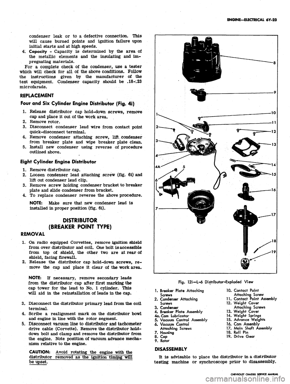
Rg.
121-L-6 Distributor-Exploded View
1.
Breaker Plate Attaching
Screws
2.
Condenser Attaching
Screws
3. Condenser
4.
Breaker Plate Assembly
4a.
Cam Lubricator
5. Vacuum Control Assembly
6. Vacuum Control
Attaching Screws
7. Housing
8. Cap
9. Rotor
DISASSEMBLY
10.
Contact Point
Attaching Screw
11.
Contact Point Assembly
12.
Weight Cover
Attaching Screws
13.
Weight Cover
14.
Weight Springs
15.
Advance Weights
16. Cam Assembly
17.
Main Shaft Assembly
18.
Roll Pin
19.
Drive Gear
It is advisable to place the distributor in a distributor
testing machine or synchroscope prior to disassembly.
CHEVROLET CU
SERVICE MANUAL
Page 351 of 659
ENGINE-ELECTRICAL 6Y-26
INSTALLATION-ENGINE NOT DISTURBED
(ALL MODELS)
1.
Turn the rotor about 1/8 turn in a clockwise direc-
tion past the mark previously placed on the distribu-
tor housing to locate rotor.
2.
Push the distributor down into position in the block
with the housing in a normal "installed" position
(fig. 15i).
NOTE: It may be necessary to move rotor
slightly to start gear into mesh with camshaft
gear, but rotor should line up with the mark
when distributor is down in place.
3.
Tighten the distributor clamp bolt snugly and con-
nect vacuum line. Connect primary wire to coil
terminal and install cap. Also install spark plug and
high tension wires if removed.
NOTE: It is important that the spark plug wires
be installed in their proper location in the
supports.
4.
Time ignition as previously described under Tune-
Up in Section 6.
INSTALLATION-ENGINE DISTURBED
(ALL MODELS)
1.
Locate No. 1 piston in firing position by either of two
methods described below,
a. Remove No. 1 spark plug and, with finger on plug
hole,
crank engine until compression is felt in the
No.
1 cylinder. Continue cranking until timing
mark on crankshaft pulley lines up with timing
tab attached to engine front cover.
b.
Remove rocker cover (left bank on V-8 engines)
and crank engine until No. 1 intake valve closes
and continue to crank slowly about 1/3 turn until
CENTRIFUGAL
jS ADVANCE
ROTATING
POLE PIECE
STATIONARY
POLE PIECE
MAGNETIC
PICKUP
ASSEMBLY
VACUUM
ADVANCE
DISTRIBUTOR
HOUSING
Fig.
151—Six Cylinder Engine Distributor
Fig.
16i—Magnetic Pulse Distributor Components
CHEVROLET CHASSIS SERVICE MANUAL