front brakes CHEVROLET CAMARO 1967 1.G Chassis Owner's Guide
[x] Cancel search | Manufacturer: CHEVROLET, Model Year: 1967, Model line: CAMARO, Model: CHEVROLET CAMARO 1967 1.GPages: 659, PDF Size: 114.24 MB
Page 483 of 659
WHEELS AND TIRES 10-3
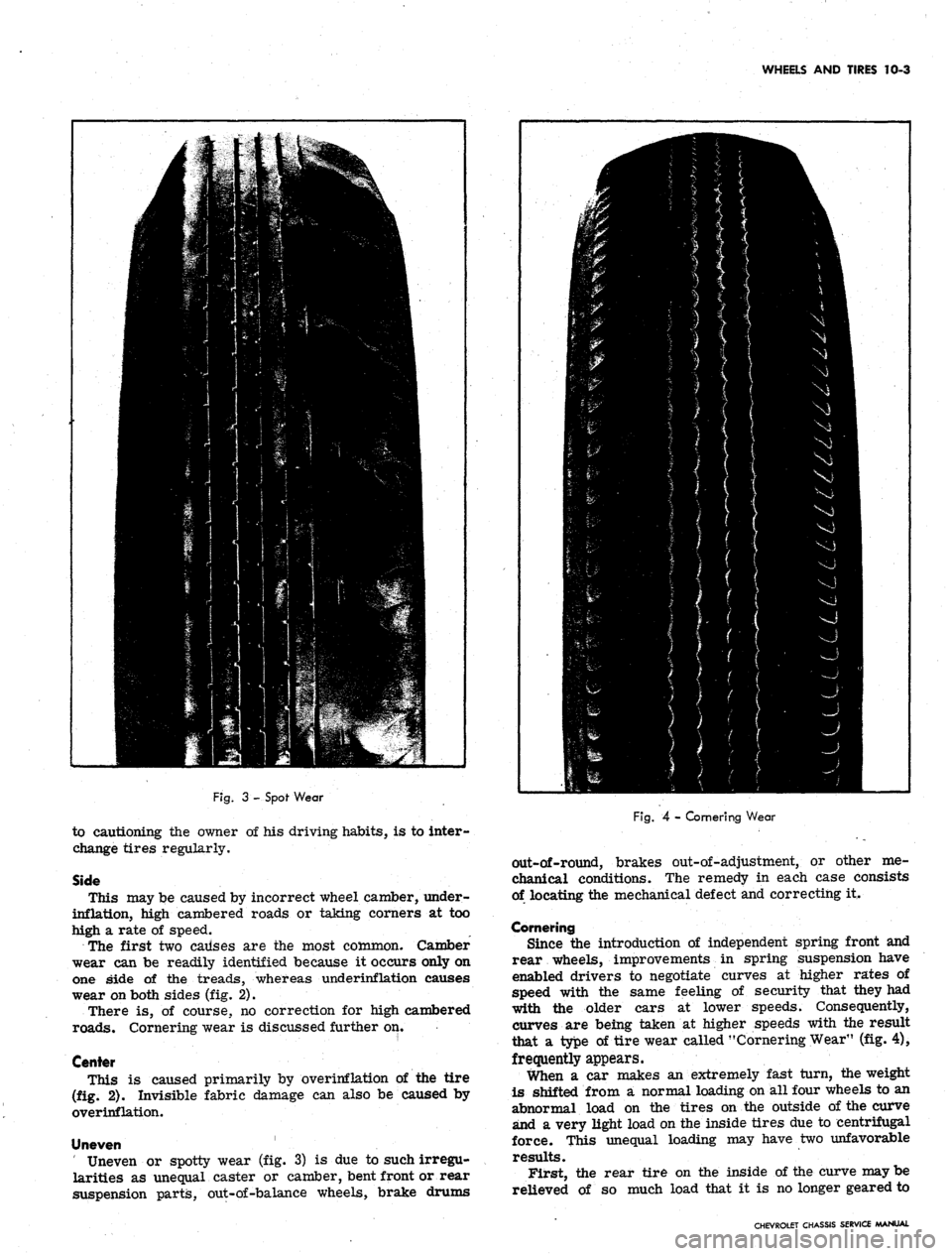
Fig.
3 - Spof Wear
to cautioning the owner of his driving habits, is to inter-
change tires regularly.
Side
This may be caused by incorrect wheel camber, under-
inflation, high cambered roads or taking corners at too
high a rate of speed.
The first two causes are the most common. Camber
wear can be readily identified because it occurs only on
one side of the treads, whereas underinflation causes
wear on both sides (fig. 2).
There is, of course, no correction for high cambered
roads.
Cornering wear is discussed further on.
Center
This is caused primarily by overinflation pf the tire
(fig. 2). Invisible fabric damage can also be caused by
overinflation.
Uneven
Uneven or spotty wear (fig. 3) is due to such irregu-
larities as unequal caster or camber, bent front or rear
suspension parts, out-of-balance wheels, brake drums
Fig.
4 - Cornering Wear
out-of-round, brakes out-of-adjustment, or other me-
chanical conditions. The remedy in each case consists
of locating the mechanical defect and correcting it.
Cornering
Since the introduction of independent spring front and
rear wheels, improvements in spring suspension have
enabled drivers to negotiate curves at higher rates of
speed with the same feeling of security that they had
with the older cars at lower speeds. Consequently,
curves are being taken at higher speeds with the result
that a type of tire wear called "Cornering Wear" (fig. 4),
frequently appears.
When a car makes an extremely fast turn, the weight
is shifted from a normal loading on all four wheels to an
abnormal load on the tires on the outside of the curve
and a very light load on the inside tires due to centrifugal
force. This unequal loading may have two unfavorable
results.
First, the rear tire on the inside of the curve may be
relieved of so much load that it is no longer geared to
CHEVROLET CHASSIS SERVICE MANUAL
Page 485 of 659
WHEELS AND TIRES 10-5
WHEELS
The wheel and tire assembly should be removed from
vehicles equipped with disc brakes to properly perform
balancing operations. This is necessary due to drag of
the spring loaded brake shoes on the disc.
Static Balancing (W/Tire)
Static Balance (still balance) is the equal distribution
of weight of the wheel and tire assembly about the axis
of rotation so that the assembly has no tendency to rotate
by
itself.
Static unbalance causes the pounding action of
the front wheels that is called "tramp".
To correct static unbalance (front and rear): The
quickest and best methods to correct static unbalance
are through the use of wheel balancers which are com-
mercially available. Refer to the Information and in-
structions included with these balaricers.
Dynamic Balancing (W/Tire)
Dynamic Balance (running balance) requires the wheel
to be not only in static balance, but balanced and running
smoothly while turning on an axis which runs through the
centerline of the wheel and tire perpendicular to the axis
of rotation.
The quickest and best methods of testing and correcting
dynamic unbalance are by the use of dynamic wheel
balancers which are commercially available. These bal-
ancers include all necessary information on where and
how the balancing weights should be placed. The follow-
ing information, however, will help in the correction of
dynamic balance.
NOTE:
Before attempting to balance the
wheels, check to be certain that no foreign
matter has been trapped in the wheel ventila-
tion slots or in the accessory wheel discs. This
is especially important if the vehicle has been
run in soft mud and then parked in freezing
weather.
When a wheel that is statically unbalanced is dynam-
ically in balance the dynamic balance can be retained
while correcting "the static balance by installing the cor-
rective weights so that half of the weight required is
placed on the inner edge of the rim and the other half
on the outer edge of the rim.
Dynamic unbalance can be corrected without destroying
static balance by installing weights so half of weight
required for dynamic balance is placed on the rim op-
posite the heavy point, while the other half is placed 180°
away and on the opposite side of the rim.
NOTE:
Vehicles with wire wheel covers should
have the wheels balanced with the wire wheel
covers installed on the wheels.
Run Out (W/OTire)
The wheels should not run out (wobble) more than
1/16" as measured on the side of the rim at the base
of the tire. Excessive run-out is the result of a bent
wheel, an improperly mounted wheel, worn knuckle bear-
ings or steering connections. These parts should be
checked for correct adjustment, proper alignment and
wear whenever excessive run-out is encountered.
The wheels should also run concentric with the steering
knuckle spindle within 1/16 inch as measured on the tire
bead seat of the rim with the tire removed.
Wheel run-out, eccentricity and balance are closely
associated with steering and front wheel alignment.
Further information on these subjects will be found under
"Suspension".
Cleaning Aluminum Wheels
Do not use wire brush or abrasive cleaners when
cleaning wheels. Use only cleaners that will not react
with aluminum.
SERVICE OPERATIONS
TIRES
Removal
Dismounting tubeless tires presents no problems if the
correct procedures are used and the following precau-
tions observed.
1.
Remove the valve cap and valve core. Let out all the
air.
2.
Press the inner side of the tire into the rim well.
Use bead loosening tool or if regular tire irons are
used, take particular care not to injure or tear the
sealing ribs on the bead.
CAUTION: Never use tire irons with sharp
edges or corners.
3.
Using tire irons on the opposite side, remove bead,
taking small "bites" around the rim.
4.
Turn the tire over, and use two tire irons, one be-
tween the rim flange and the bead to pry the rim
upward, the other iron to pry outward between the
bead seat and the bead.
Installation
Extreme care must be exercised to prevent injury to
the sealing bead and circumferential bead when forcing
tire over rim.
1.
Apply a light film of Ruglyde or other suitable rubber
lubricant to sealing bead of tire.
NOTE:
The use of excessive lubrication may
lead to rim slippage and subsequent breaking of
air seal.
2.
Carefully mount the outer bead in usual manner by
using tire irons, taking small "bites" around rim,
being careful not to injure the tire bead.
CAUTION: DO NOT use a hammer, as damage
to the bead will result.
3.
Install the inner bead in the same manner.
NOTE:
If a seal cannot be effected in the fore-
going manner with the rush of air it can be
, accomplished by applying to the circumference
of the tire a tire mounting band or heavy sash
cord and tightening with the use of a tire iron.
On tire mounting machines, bouncing the tire
assembly is not required. The tire should be
CHEVROLET CHASSIS SERVICE MANUAL
Page 504 of 659
CHASSIS SHEET METAL 11-17
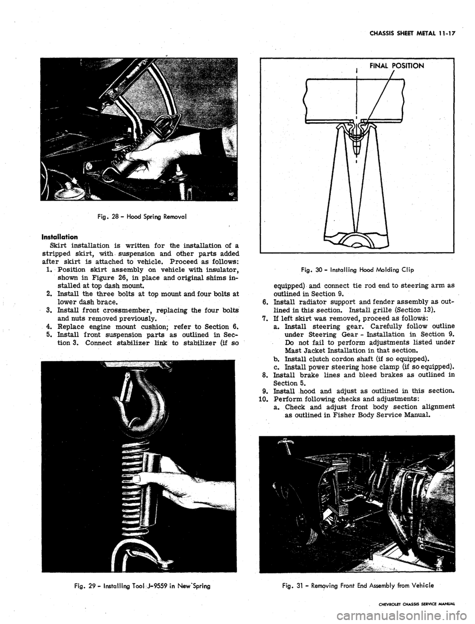
Fig.
28- Hood Spring Removal
Installation
Skirt installation is written for the installation of a
stripped skirt, with suspension and otiier parts added
after skirt is attached to vehicle. Proceed as follows:
1.
Position skirt assembly on vehicle with insulator,
shown in Figure 26, in place and original shims in-
stalled at top dash mount
2.
Install the three bolts at top mount and four bolts at
lower dash brace.
3.
Install front crossmember, replacing the four bolts
and nuts removed previously.
4.
Replace engine mount cushion; refer to Section 6.
5.
Install front suspension parts as outlined in Sec-
tion 3. Connect stabilizer link to stabilizer (if so
FINAL POSITION
Fig.
30 - Installing Hood Molding Clip
equipped) and connect tie rod end to steering arm as
outlined in Section 9.
6. Install radiator support and fender assembly as out-
lined in this section. Install grille (Section 13).
7.
If left skirt was removed, proceed as follows:
a. Install steering gear. Carefully follow outline
under Steering Gear - Installation in Section 9.
Do not fail to perform adjustments listed under
Mast Jacket Installation in that section.
b.
Install clutch cordon shaft (if so equipped).
c. Install power steering hose clamp (if so equipped).
8. Install brake lines and bleed brakes as outlined in
Section 5.
9. Install hood and adjust as outlined in this section.
10.
Perform following checks and adjustments:
a. Check and adjust front body section alignment
as outlined in Fisher Body Service Manual.
Fig.
29 - Installing Tool J-9559 in Nev/Spring
Fig.
31 - Removing Front End Assembly from Vehicle
CHEVROLET CHASSIS SERVICE MANUAL
Page 506 of 659
5.
6.
7.
8.
2.
Install all fender mounting screws, replacing original
shimming. Refer to removal procedure for screw
location.
3.
Install hydraulic lines at main cylinder and right
hand skirt. Install fuel line at right hand skirt.
4.
Install steering gear as outlined in Section 9. Do
not fail to perform adjustment procedure listed under
Mast Jacket - Installation.
CAMARO
INDEX
Page
General Description 20
Maintenance and Adjustments 20
Hood / . 20
Hinge 20
Bumpers ' . . . 20
Catch Assembly 21
Lock . 21
Fenders 21
Sheet Metal 22
CHASSIS SHEET METAL 11-19
Install pitman arm as outlined in Section 9 under
Maintenance and Adjustments - Steering Gear Ad-
justments.
Remove jack stands and jack.
Bleed brakes as outlined in Section 5.
Perform body alignment as outlined in Fisher Body
Service Manual.
Page
Component Part Replacement . 22
Battery Tray 22
Radiator Support 22
Fender and Skirt Assembly 22
Hood Assembly . 22
Lock and Catch Assembly 22
Trim and Insulation . . . 24
Cowl Vent Grille . . 24
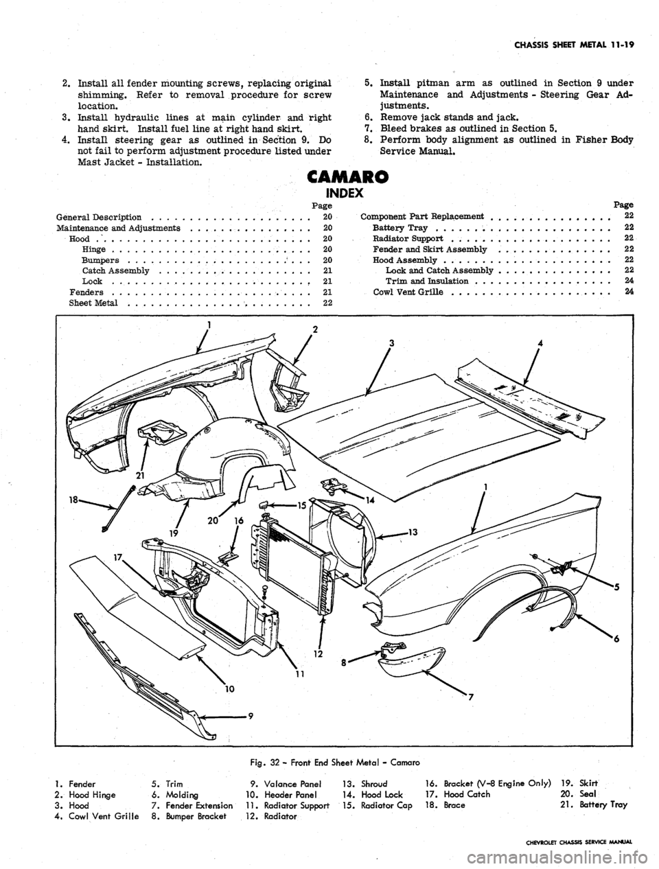
Fig.
32 - Front End Sheet Metal - Camaro
1.
Fender
2.
Hood Hinge
3. Hood
4.
Cowl Vent Grille
5. Trim
6. Molding
7. Fender Extension
8. Bumper Bracket
9. Valance Pane!
10.
Header Panel
11.
Radiator Support
12.
Radiator
13.
14.
15.
Shroud
Hood Lock
Radiator Cap
16.
17.
18.
Bracket (V-8
Hood Catch
Brace
Engine
Only)
19.
20.
21.
Skirt
Seal
Battery
Tray
CHEVROLET CHASSIS SERVICE MANUAL
Page 629 of 659
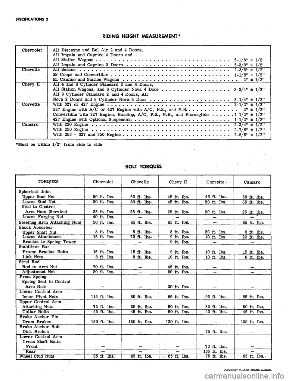
SPECIFICATIONS
2
RIDING HEIGHT MEASUREMENT*
Chevrolet
All Biscayne
and Bel Air 2 and 4
Doors,
All Impala
and
Caprice
4
Doors
and
All Station Wagons
. . . .
All Impala
and
Caprice
2
Doors
. . . . .
5-1/8"
± 1/2"
5-3/8"
± 1/2"
Chevelle
All Sedans
SS Coupe
and
Convertible
El Camino
and
Station W*
1-3/811
± 1/2"
1-1/8"
± 1/2"
..
2" ± 1/2"
Chevy
u
All
4 and 6
Cylinder Standard
2 and 4
Doors,
All Station Wagons,
and 6
Cylinder Nova
4
Door
All
8
Cylinder Standard
2 and 4
Doors,
All
Nova
2
Doors
and 8
Cylinder Nova
4
Door
. . .
3-3/4'
3-1/4'
±
1/2'
±
1/2'
Corvette
With
327 or 427
Engine
. . . .
327 Engine with
A/C or 427
Engine with
A/C,
P.S.,.and
P.B
Convertible with
327
Engine, Hardtop,
A/C, P.S., P.B., and
Powerglide
427 Engine with Optional Suspension
.
2-1/2"
.
2"
1-1/2"
1-1/2"
±
1/2"
±1/2"
±
1/2"
±
1/2"
Camaro
With
230
Engine
..... . . .
With
250
Engine
.... ...
With
283 - 327 and
350 Engine
2-3/4"
2-7/8"
2-5/8"
± 1/2"
± 1/2"
± 1/2"
•Must be within 1/2" from side to side
BOLT TORQUES
TORQUES
Spherical Joint
Upper Stud
Nut
Lower Stud
Nut
Stud
to
Control
Arm Nuts (Service)
Lower Forging
Nut
Steering
Arm
Attaching Nuts
Shock Absorber
Upper Shaft
Nut
Lower Attachment
Bracket
to
Spring Tower
Stabilizer
Bar
Frame Bracket Bolts
Link Nuts
Strut
Rod
Rod
to Arm Nut
Adjustment
Nut
Front Spring
Spring Seat
to
Control
Arm Nuts
Lower Control
Arm
Inner Pivot Nuts
Upper Control Arm
Attaching Nuts
Collar Bolts
Brake Anchor Pin
Drum Brakes
Brake Anchor Bolt
Disk Brakes
Lower Control Arm
Cross Shaft Bolts
Front
Rear .
Wheel Stud Nuts
Chevrolet
50 ft. lbs.
80 ft lbs.
25 ft. lbs.
40 ft. lbs.
50 ft. lbs.
8 ft. lbs.
15 ft. lbs.
—
15 ft lbs.
8 ft. lbs.
70 ft lbs.
80 ft lbs.
115 ft lbs.
75 ft lbs.
45 ft lbs.
130 ft lbs.
—
65 ft lbs.
Chevelle
50 ft lbs.
80 ft lbs.
25 ft. lbs.
—
85 ft lbs.
8 ft lbs.
20 ft lbs.
—
15 ft lbs.
8 ft lbs.
—
80 ft lbs.
50 ft. lbs.
45 ft. lbs.
130 ft lbs.
—
65 ft lbs.
Chevy H
45 ft lbs.
45 ft lbs.
25 ft lbs.
—
65 ft. lbs.
8 ft lbs.
9 ft lbs.
9 ft. lbs.
9 ft. lbs.
10 ft. lbs.
45 ft lbs.
80 ft lbs.
30 ft lbs.
65 ft lbs.
50 ft. lbs.
50 ft lbs.
130 ft lbs.
_
—
65 ft lbs.
Corvette
45 ft lbs.
20 ft lbs.
20 ft lbs.
—
20 ft lbs.
10 ft lbs.
—
10 ft lbs.
10 ft. lbs.
—
95 ft lbs.
35 ft lbs.
40 ft lbs.
75 ft lbs..
70 ft lbs.
135 ft lbs.
75 ft lbs.
Camaro
50 ft lbs.
65 ft lbs.
25 ft lbs.
—
85 ft lbs.
8 ft lbs.
20 ft lbs.
.
—
15 ft. lbs.
8 ft._lbs.
_
85 ft lbs.
50 ft lbs.
45 ft lbs.
130 ft lbs.
_
—
65 ft lbs.
CHEVROLET CHASSIS SERVICE MANUAL
Page 632 of 659

SPECIFICATIONS
5
BRAKES
SECTION
5
Type
Brake Drums
Diameter
Maximum
Out of Rou
Maximum Rebor©
id
Brake Shoes
Width Front
Rear
Length Primary
Secondary
Wheel Cylinder Diameter
Front
Rear
Chevrolet
Chevelle
Chevy
H
Camaro
Duo Servo Self Adjusting
11"
9-1/2
9-1/2
.008"
.060"
2-3/4
2
9-1/4
11-41/64
1-3/16
1
2-1/2
2
9
9-3/4
1-1/8
15/16
1-1/16
7/8
2-1/2
2
9
9-3/4
1-1/8
15/16
Corvette
Disc
2-7/32
5-31/32
1-7/8
1-3/8
TORQUE CHART
APPLICATION
Brake Pipe Distribution
and
Switch Assembly Mounting
Screws
Main Cylinder
to
Firewall
Mounting Nuts
Push
Rod
Clevis
Nut
Brake Hydraulic
Pipe
to
Main
Cylinder
and
Switch Connections
Brake Hose
to
Brake
Assembly Connection
Parking Brake Equalizer
Check
Nut
Hydraulic Brake
Pipe Connections
Rear Brake Hose
to
Rear
Brake Line "T" Connection
Caliper Half Retaining Bolts
Caliper
to
Mounting Bracket
Retaining Bolts
Chevrolet
24
lb. ft
14
lb. ft
100
lb. in.
(Front Line)
115
lb. in.
(Rear Line)
23
lb. ft
85
lb. in.
110
lb. in.
113
lb. in.
130
lb. ft
130
lb. ft
Chevelle
60
lb. in.
24
lb. ft
14
lb. ft
115
lb. in.
23
lb. ft
85
lb. in.
100
lb. in.
(Front)
120
lb. in.
(Rear)
113
lb. in.
130
lb. ft
130
lb. ft
Chevy
n
150
lb. in.
24
lb. ft
14
lb. ft
115
lb. in.
2^
lb. ft
—
100
lb. in.
65
lb. in.
130
lb. ft
130
lb. ft
Camaro
24
lb. ft
14
lb. ft
115
lb. in.
23
lb. ft
85
lb. in.
100
lb. in.
113
lb. in.
130
lb. ft
130
lb. ft
Corvette
90
lb. in.
24
lb. ft.
14
lb. ft.
115
lb. in.
23
lb. ft
70
lb. in.
100
lb. in.
113
lb. in.
130
lb. ft
130
lb. ft
CHEVROLET CHASSIS SERVICE MANUAL
Page 651 of 659
SPECIFICATIONS 24
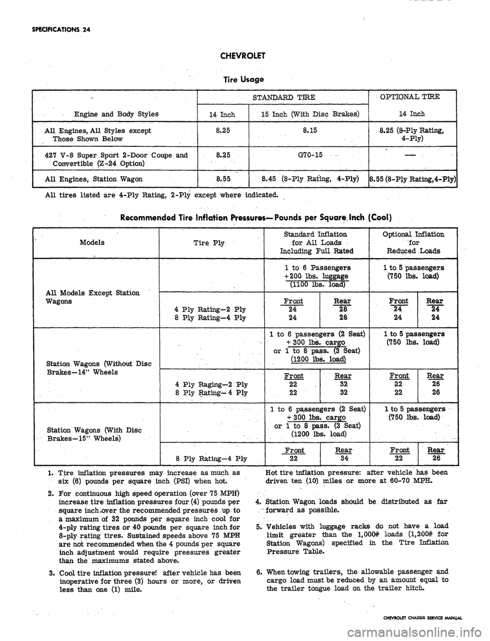
CHEVROLET
Engine and Body Styles
All. Engines, All Styles except
Those Shown Below
427 V-8 Super Sport 2-Door Coupe and
Convertible (Z-24 Option)
All Engines, Station Wagon
Tire
14 Inch
8.25
8.25
8.55
Usage
STANDARD TIRE
15 Inch (With Disc
8.15
G70-15
8.45 (8-Ply Rating,
Brakes)
4-Ply)
OPTIONAL TIRE
14 Inch
8.25 (a-Ply Rating,
4-Ply)
. —. ...
8.55 (8-Ply Rating,4-Ply)
All tires listed are 4-Ply Rating, 2-Ply except where indicated.
Recommended Tire Inflation Pressures—Pounds per Square.Inch (Cool)
' Models
All Models Except Station
Wagons
Station Wagons (Without Disc
Brakes—14" Wheels
Station Wagons (With Disc
Brakes-15" Wheels)
Tire Ply-
4 Ply Rating-2 Ply
8 Ply Rating-4 Ply
4 Ply Raging—2 Ply
8 Ply Rating-4 Ply
8 Ply Rating-4 Ply
Standard Inflation
for All Loads
Including Full Rated
1 to 6 Passengers
+ 200 lbs. luggage
(1100 lbs. load)
Front
24
24
Rear
28
28
1 to 6 passengers (2 Seat)
+ 300 lbs. cargo
or 1 to 8 pass. (3 Seat)
(1200 lbs. load)
Front
22
22
Rear
32
32
1 to 6 passengers (2 Seat)
+ 300 lbs. cargo
or 1 to 8 pass. (3 Seat)
(1200 lbs. load)
Front
22
Rear
34
Optional Inflation
ior
Reduced Loads
1 to 5 passengers
(750 lbs. load)
Front
"24~
24
Rear
24
24
1 to 5 passengers
(750 lbs. load)
Front
22
22
Rear
26
26
1 to 5 passengers
(750 lbs. load)
Front
22
Rear
26
1.
Tire inflation pressures may increase as much as
six (6) pounds per square inch (PSI) when hot
2.
For continuous high speed operation (over 75 MPH)
increase tire inflation pressures four (4) pounds per
square inch .over the recommended pressures up to
a maximum of 32 pounds per square inch cool for
4-ply rating tires or 40 pounds per square inch for
8-ply rating tires. Sustained speeds above 75 MPH
are not recommended when the 4 pounds per square
inch adjustment would require pressures greater
than the maximums stated above.
3.
Cool tire inflation pressure? after vehicle has been
inoperative for three (3) hours or more, or driven
less than one (1) mile.
Hot tire inflation pressure: after vehicle has been
driven ten (10) miles or more at 60-70 MPH.
4.
Station Wagon loads should be distributed as far
forward as possible.
5. Vehicles with luggage racks do not have a load
limit greater than the l,000# loads (l,200# for
Station Wagons) specified in the Tire Inflation
Pressure Table.
6. When towing trailers, the allowable passenger and
cargo load must be reduced by an amount equal to
the trailer tongue load on the trailer hitch.
CHEVROLET CHASSIS SERVICE MANUAL