battery replacement CHEVROLET CAMARO 1967 1.G Chassis Workshop Manual
[x] Cancel search | Manufacturer: CHEVROLET, Model Year: 1967, Model line: CAMARO, Model: CHEVROLET CAMARO 1967 1.GPages: 659, PDF Size: 114.24 MB
Page 7 of 659
GENERAL INFORMATION 0-5
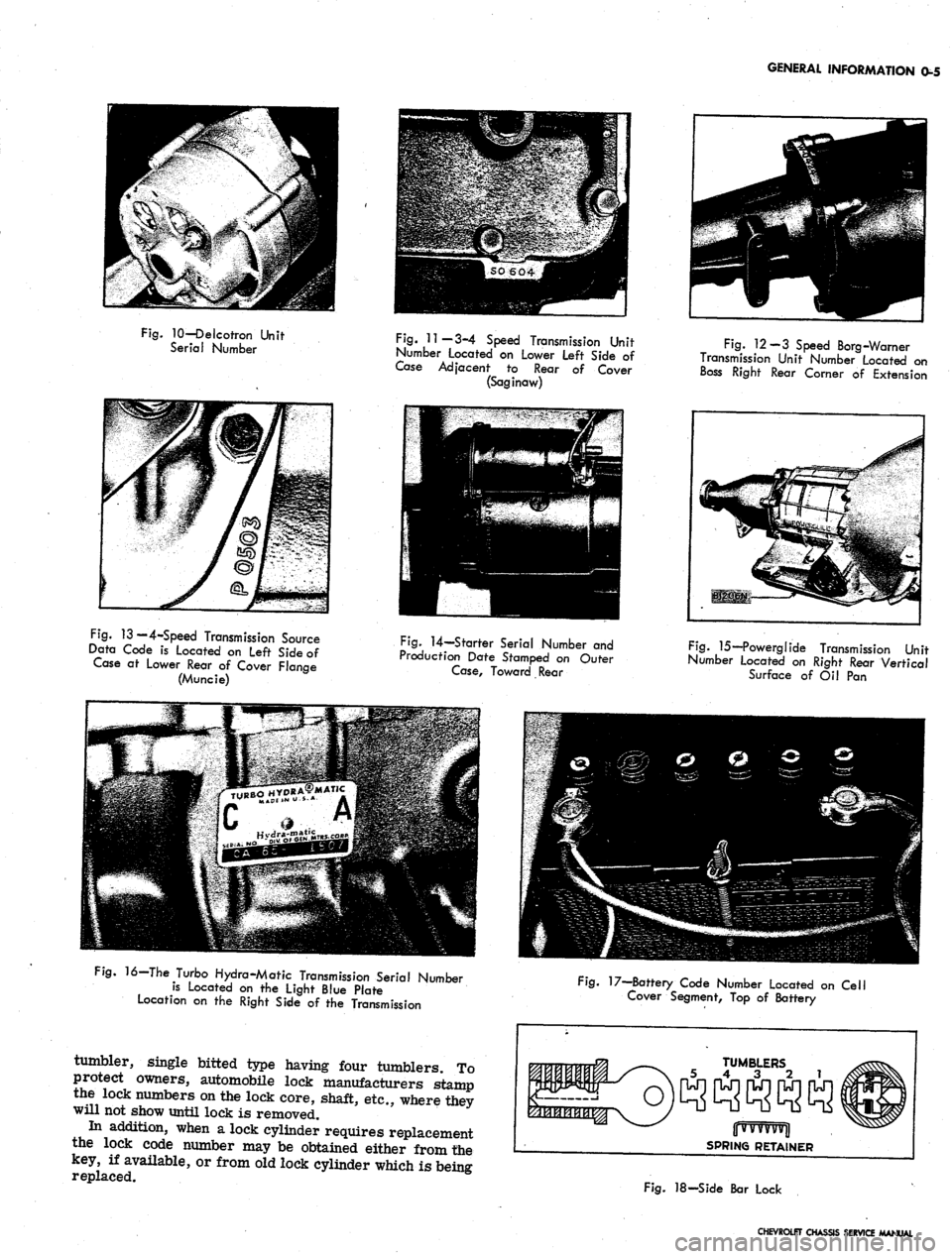
Fig.
10—Delcotron Unit
Serial Number
Fig.
11—3-4 Speed Transmission Unit
Number Located on Lower Left Side of
Case Adjacent to Rear of Cover
(Saginaw)
Fig.
12-3 Speed Borg-Warner
Transmission Unit Number Located on
Boss Right Rear Comer of Extension
Fig.
13 — 4-Speed Transmission Source
Data Code is Located on Left Side of
Case at Lower Rear of Cover Flange
(Muncie)
Fig.
14—Starter Serial Number and
Production Date Stamped on Outer
Case,
Toward Rear
Fig.
15—Powerglide Transmission Unit
Number located on Right Rear Vertical
Surface of Oil Pan
16—The Turbo Hydra-Matic Transmission Serial Number
is Located on the Light Blue Plate
Location on the Right Side of the Transmission
tumbler, single bitted type having four tumblers. To
protect owners, automobile lock manufacturers stamp
the lock numbers on the lock core, shaft, etc., where they
will not show until lock is removed.
In addition, when a lock cylinder requires replacement
the lock code number may be obtained either from the
key, if available, or from old lock cylinder which is being
replaced.
Fig.
17—Battery Code Number Located on Cell
Cover Segment, Top of Battery
TUMBLERS
5 4 3 2 1
jjwvvvvvjl
SPRING RETAINER
Fig.
18-Side Bar Lock
CHEVROLET CHASSIS SERVICE MANUAL
Page 26 of 659
HEATER AND AIR CONDITIONING 1A-3
linkage of this lever which will provide partial airflow
only to the defroster duct and which should be used for,
all normal defogging operations.
CORVETTE
Heater components are attached to the dash panel on
the right side of the vehicle with the air inlet assembly
on the engine side and the heater and air distributor
assemblies beneath the instrument panel within the pas-
senger compartment.
The heater operates on outside air only with the blower
receiving its air flow from the cowl vent plenum
chamber.
No water valve is utilized in the system. Therefore,
water flows through the heater core constantly while
the engine is running, keeping the core at maximum
temperature at all times.
Airflow through the system is shown in Figure 1.
Controls
Two knobs control all heater operations:
The FAN-TEMP knob is rotated to turn the blower
on and off and control blower speed and is pulled out
as desired to regulate heater temperature.
The AIR-DEF knob is the air on-and-off control as
well as the defroster control.
Temperature Damper: Door
At the heart of the heater operation is the temperature
damper door. Air from the blower follows parallel paths
through the distributor duct, with one path passing
through the heater core and the other path bypassing the
core.
The temperature damper door is placed in the duct
so that, when closed, the path of the heated air leaving
the heater core is blocked while the ambient air path
remains open. Positive closing of this door when no
heat is being called for is assured by a cam assembly
at the door operating lever. As the FAN-TEMP knob
is pulled out, the damper door is opened accordingly,
allowing varying proportions of heated air to mix with
the unheated airflow, thus providing heater outlet tem-
perature control. With the knob pulled fully out the
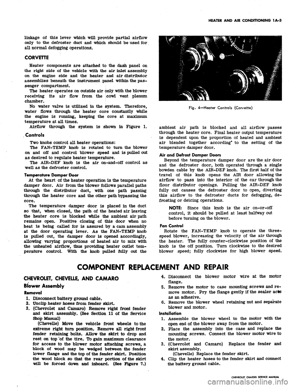
Fig.
4—Heater Controls (Corvette)
ambient air path is blocked and all airflow passes
through the heater core. Final heater output temperature
is dependent upon the proportion of heated and ambient
air blended together according* to the setting of the
temperature damper door.
Air and Defrost Damper Doors
Beyond the temperature damper door are the air door
and the defroster door, both operated through a single
bowden cable by the AIR-DEF knob. The first half of the
travel of this knob opens the AIR door allowing the
airflow to pass into the interior of the car through the
floor distributor openings. Pulling the AIR-DEF knob
fully out causes the defroster door to open, diverting
this airflow to the defroster ducts for defogging, de-
frosting or deicing operations.
NOTE: Since this knob is the air on-or-off
control, it should be pulled at least halfway out
before turning on the blower.
Fan Control
Rotate the FAN-TEMP knob to operate the three-
speed blower, increasing the velocity of the air through
the heater. The fully counter-clockwise position of the
knob is the off position. Turn clockwise to the desired
blower speed; fully clockwise for high blower speed.
COMPONENT REPLACEMENT AND REPAIR
CHEVROLET, CHEVELLE, AND CAMARO
Blower Assembly
Removal
1.
Disconnect battery ground cable.
2.
Unclip heater hoses from fender skirt.
3.
(Chevrolet and Camaro) Remove right front fender
and skirt assembly. (See Section 11 of the Service
Shop Manual)
(Chevelle) Move the vehicle front wheels to the
extreme right turn position. Remove all right front
fender retaining bolts. Allow the skirt to drop and
rest on top of the tire. To gain maximum clearance
for access to the blower motor attaching screws, a
block of wood may be wedged between the fender
lower flange and the top of the fender skirt. Position
the wood block so that the rear portion of the skirt
will be forced down and inboard. (See Figure 7.)
4.
Disconnect the blower motor wire at the motor
flange.
5.
Remove the motor to case mounting screws and re-
move motor. Pry the flange gently if the sealer acts
as an adhesive.
6. Remove the blower wheel retaining nut and separate
blower and motor.
Installation
1.
Assemble the blower wheel to the motor with the
open end of the blower away from the motor.
2.
Place the assembly into the case and replace the
mounting screws. Connect the blower motor wire to
the motor.
3.
(Chevrolet and Camaro) Replace the fender and
skirt assembly.
(Chevelle) Replace the fender skirt.
4.
Clip the heater hoses to the fender skirt and connect
the battery ground cable.
CHEVROLET CHASSIS SERVICE MANUAL
Page 29 of 659
HEATER AND AIR CONDITIONING 1A-6
CHEVROLET SHOWN AS TYPICAL
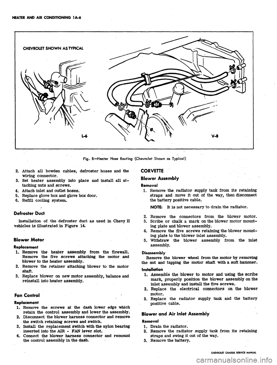
Fig.
8—Heater Hose Routing (Chevrolet Shown as Typical)
cables, defroster hoses and the
place and install all at-
4.
5.
6.
Attach all bowden
wiring connector.
Set heater assembly into
taching nuts and screws.
Attach inlet and outlet hoses.
Replace glove box and glove box door.
Refill cooling system.
Defroster Duct
Installation of the defroster duct as used in Chevy H
vehicles is illustrated in Figure 14.
Blower Motor
Replacement
1.
Remove the heater assembly from the firewall.
Remove the five screws attaching the motor and
blower to the heater assembly.
2.
Remove the retainer attaching blower to the motor
shaft.
3.
Replace blower on new motor assembly, balance and
reinstall into heater assembly.
Fan Control
Replacement
1.
Remove the screws at the dash lower edge which
retain the control assembly and lower the assembly.
2.
Disconnect the blower harness connector and remove
the switch retaining screws and switch.
3.
Install the replacement switch with the nylon bearing
inserted into the AIR - FAN lever slot.
4.
Connect the blower harness connector and remount
the control assembly in the dash.
CORVETTE
Blower Assembly
Removal
1.
Remove the radiator supply tank from its retaining
straps and move it out of the way, then disconnect
the battery positive cable.
NOTE:
It is not necessary to drain the radiator.
2.
Remove the connectors from the blower motor.
3.
Scribe or chalk a mark on the blower motor mount-
ing plate and blower assembly.
4.
Remove the five screws retaining the blower mount-
ing plate to the blower inlet assembly.
Withdraw the blower assembly from the inlet
5.
assembly.
Disassembly
Remove the blower wheel from the motor by removing
the nut and tapping the motor shaft with a soft hammer.
Installation
1.
Assemble the blower to motor and using the scribe
mark, properly position the blower assembly on the
inlet assembly and install the five screws.
2.
Replace the electrical connectors on the blower
motor.
3.
Replace the radiator supply tank and the battery
positive cable.
Blower and Air Inlet Assembly
Removal
1.
Drain the radiator.
2.
Remove the radiator supply tank from its retaining
straps and swing it out of the way.
3.
Remove the battery.
CHEVROLET CHASSIS SERVICE MANUAL
Page 85 of 659
HEATER AND AIR CONDITIONING 1A-62
2.
Insert the evaporator assembly into the outlet case
half and mount the evaporator, thermostatic switch,
and cable to the case.
3.
Install the face plate to the case and install control
retaining nuts and knobs.
4.
Assemble the case halves and mount the evaporator
pipe clamp.
5. Install the evaporator assembly as previously
described under EVAPORATOR.
BLOWER ASSEMBLY
Four-Season System
Chevrolet and Camaro
Removal
1.
Disconnect battery ground cable.
2.
Remove the right front fender and skirt assembly.
3.
Disconnect the motor wire at the flange connector.
4.
Disconnect the rubber air cooling tube from the
motor.
5. Remove the motor to case attaching screws and re-
move the blower assembly. If the sealer acts as an
adhesive, pry the assembly carefully away from the
6. Remove the blower from the motor shaft.
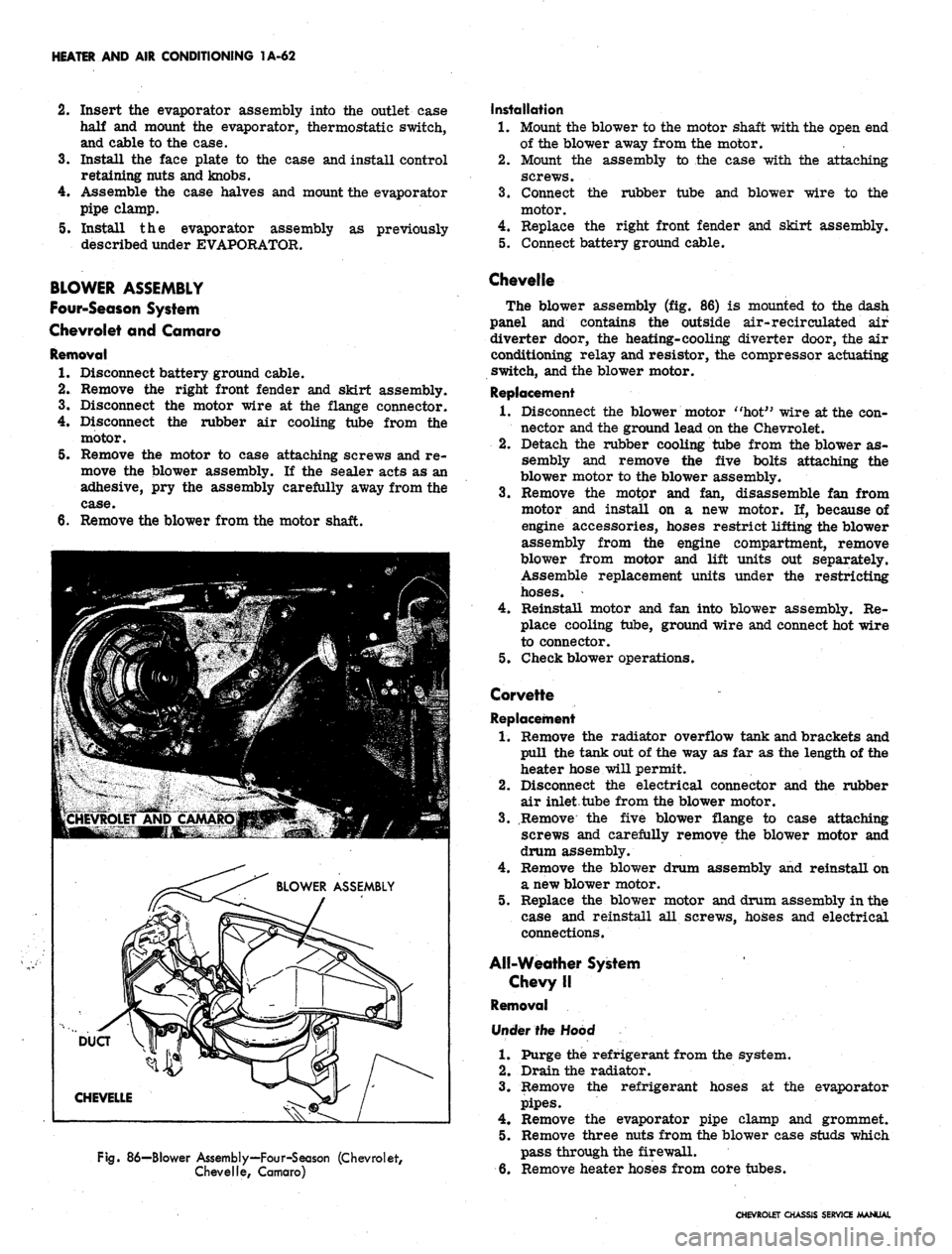
Fig.
86—Blower Assembly—Four-Season (Chevrolet,
Chevelle, Camaro)
Installation
1.
Mount the blower to the motor shaft with the open end
of the blower away from the motor.
2.
Mount the assembly to the case with the attaching
screws.
3.
Connect the rubber tube and blower wire to the
motor.
4.
Replace the right front fender and skirt assembly.
5. Connect battery ground cable.
Chevelle
The blower assembly (fig. 86) is mounted to the dash
panel and contains the outside air-recirculated air
diverter door, the heating-cooling diverter door, the air
conditioning relay and resistor, the compressor actuating
switch, and the blower motor.
Replacement
1.
Disconnect the blower motor "hot" wire at the con-
nector and the ground lead on the Chevrolet.
2.
Detach the rubber cooling tube from the blower as-
sembly and remove the five bolts attaching the
blower motor to the blower assembly.
3.
Remove the motor and fan, disassemble fan from
motor and install on a new motor. If, because of
engine accessories, hoses restrict lifting the blower
assembly from the engine compartment, remove
blower from motor and lift units out separately.
Assemble replacement units under the restricting
hoses.
4.
Reinstall motor and fan into blower assembly. Re-
place cooling tube, ground wire and connect hot wire
to connector.
5. Check blower operations.
Corvette
Replacement
1.
Remove the radiator overflow tank and brackets and
pull the tank out of the way as far as the length of the
heater hose will permit.
2.
Disconnect the electrical connector and the rubber
air inlet tube from the blower motor.
3.
Remove the five blower flange to case attaching
screws and carefully remove the blower motor and
drum assembly.
4.
Remove the blower drum assembly and reinstall on
a new blower motor.
5. Replace the blower motor and drum assembly in the
case and reinstall all screws, hoses and electrical
connections.
All-Weather System
Chevy II
Removal
Under the Hood
1.
Purge the refrigerant from the system.
2.
Drain the radiator.
3.
Remove the refrigerant hoses at the evaporator
pipes.
4.
Remove the evaporator pipe clamp and grommet.
5. Remove three nuts from the blower case studs which
pass through the firewall.
6. Remove heater hoses from core tubes.
CHEVROLET CHASSIS SERVICE MANUAL
Page 91 of 659
HEATER AND AIR CONDITIONING 1A-68
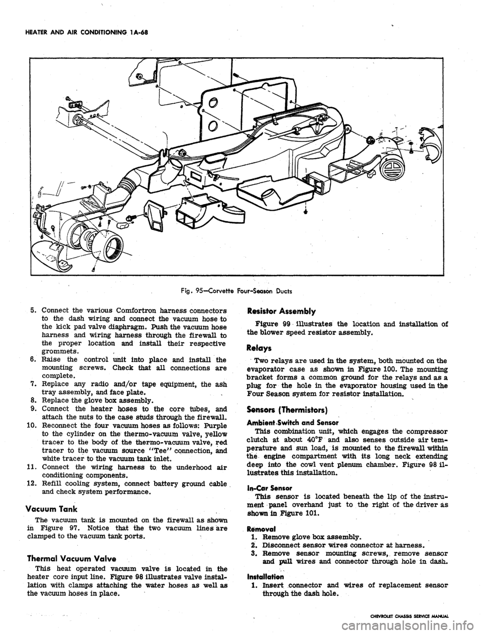
Fig.
95—Corvette Four-Season Ducts
5. Connect the various Comfortron harness connectors
to the dash wiring and connect the vacuum hose to
the kick pad valve diaphragm. Push the vacuum hose
harness and wiring harness through the firewall to
the proper location and install their respective
grommets.
6. Raise the control unit into place and install the
mounting screws. Check that all connections are
complete.
7. Replace any radio and/or tape equipment, the ash
tray assembly, and face plate.
8. Replace the glove box assembly.
9. Connect the heater hoses to the core tubes, and
attach the nuts to the case studs through the firewall.
10.
Reconnect the four vacuum hoses as follows: Purple
to the cylinder on the thermo-vacuum valve, yellow
tracer to the body of the thermo-vacuum valve, red
tracer to the vacuum source "Tee" connection, and
white tracer to the vacuum tank inlet.
11.
Connect the wiring harness to the underhood air
conditioning components.
12.
Refill cooling system, connect battery ground cable
and check system performance.
Vacuum Tank
The vacuum tank is mounted on the firewall as shown
in Figure 97. Notice that the two vacuum lines are
clamped to the vacuum tank ports. *
Thermal Vacuum Valve
This heat operated vacuum valve is located in the
heater core input line. Figure 98 illustrates valve instal-
lation with clamps attaching the water hoses as well as
the vacuum hoses in place.
Resistor Assembly
Figure 99 illustrates the location and installation of
the blower speed resistor assembly.
Relays
Two relays are used in the system, both mounted on the
evaporator case as shown in Figure 100. The mounting
bracket forms a common ground for the relays and as a
plug for the hole in the evaporator housing used in the
Four Season system for resistor installation.
Sensors (Thermistors)
Ambient Switch and Sensor
This combination unit, which engages the compressor
clutch at about 40°F and also senses outside air tem-
perature and sun load, is mounted to the firewall within
the engine compartment with its long neck extending
deep into the cowl vent plenum chamber. Figure 98 il-
lustrates this installation,
In-Car Sensor
This sensor is located beneath the lip of the instru-
ment panel overhand just to the right of the driver as
shown in Figure 101.
Removal
1.
Remove glove box assembly.
2.
Disconnect sensor wires connector at harness.
3.
Remove sensor mounting screws, remove sensor
and pull wires and connector through hole in dash.
Installation
1.
Insert connector and
through the dash hole.
wires of replacement sensor
CHEVROLET CHASSIS SERVICE MANUAL
Page 96 of 659
HEATER AND AIR CONDITIONING 1A-73
Fig.
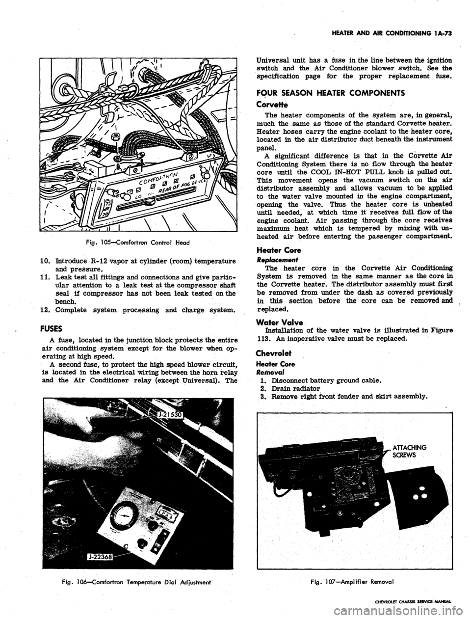
105—Comfortron Control Head
10.
Introduce R-12 vapor at cylinder (room) temperature
and pressure.
11.
Leak test all fittings and connections and give partic-
ular attention to a leak test at the compressor shaft
seal if compressor has not been leak tested on the
bench.
12.
Complete system processing and charge system.
FUSES
A fuse, located in the junction block protects the entire
air conditioning system except for the blower when op-
erating at high speed.
A second fuse, to protect the high speed blower circuit,
is located in the electrical wiring between the horn relay
and the Air Conditioner relay (except Universal). The
Universal unit has a fuse in the line between the ignition
switch and the Air Conditioner blower switch. See the
specification page for the proper replacement fuse.
FOUR SEASON HEATER COMPONENTS
Corvette
The heater components of the system are, in general,
much the same as those of the standard Corvette heater.
Heater hoses carry the engine coolant to the heater core,
located in the air distributor duct beneath the instrument
panel.
A significant difference is that in the Corvette Air
Conditioning System there is no flow through the heater
core until the COOL IN-HOT PULL knob is pulled out.
This movement opens the vacuum switch on the air
distributor assembly and allows vacuum to be applied
to the water valve mounted in the engine compartment,
opening the valve. Thus the heater core is unheated
until needed, at which time it receives full flow of the
engine coolant. Air passing through the core receives
maximum heat which is tempered by mixing with un-
heated air before entering the passenger compartment.
Heater Core
Replacement
The heater core in the Corvette Air Conditioning
System is removed in the same manner as the core in
the Corvette heater. The distributor assembly must first
be removed from under the dash as covered previously
in this section before the core can be removed and
replaced.
Water Valve
Installation of the water valve is illustrated in Figure
113.
An inoperative valve must be replaced.
Chevrolet
Heater Core
Removal
1.
Disconnect battery ground cable.
2.
Drain radiator
3.
Remove right front fender and skirt assembly.
Fig.
106—Comfortron Temperature Dial Adjustment
Fig.
107—Amplifier Removal
CHEVROLET CHASSIS SERVICE MANUAL
Page 97 of 659
HEATER AND AIR CONDITIONING 1A-74
Fig.
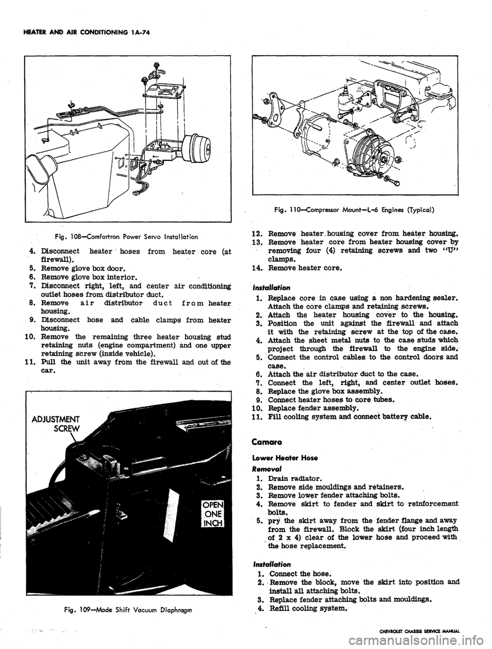
108—Comfortron Power Servo Installation
4.
Disconnect heater' hoses from heater core (at
firewall).
5. Remove glove box door.
6. Remove glove box interior.
7. Disconnect right, left, and center air conditioning
outlet hoses from distributor duct.
8. Remove air distributor duct from heater
housing.
9. Disconnect hose and cable clamps from heater
housing.
10.
Remove the remaining three heater housing stud
retaining nuts (engine compartment) and one upper
retaining screw (inside vehicle).
11.
Pull the unit away from the firewall and out of the
car.
ADJUSTMENT
SCREW
Fig.
109—Mode Shift Vacuum Diaphragm
Fig. 110'—Compressor Mount—L-6 Engines (Typical)
12.
Remove heater.housing cover from heater housing.
13.
Remove heater core from heater housing cover by
removing four (4) retaining screws and two "U"
clamps.
14.
Remove heater core.
Installation
1.
Replace core in case using a non hardening sealer.
Attach the core clamps and retaining screws.
2.
Attach the heater housing cover to the housing.
3.
Position the unit against the firewall and attach
it with the retaining screw at the top of the case.
4.
Attach the sheet metal nuts to the case studs which
project through the firewall to the engine side.
5. Connect the control cables to the control doors and
case.
6. Attach the air distributor duct to the case.
7. Connect the left, right, and center outlet hoses.
8. Replace the glove box assembly.
9. Connect heater hoses to core tubes.
10.
Replace fender assembly.
11.
Fill cooling system and connect battery cable.
Camaro
Lower Heater Hose
Removal
1.
Drain radiator.
2.
Remove side mouldings and retainers.
3.
Remove lower fender attaching bolts.
4.
Remove skirt to fender and skirt to reinforcement
bolts.
5. pry the skirt away from the fender flange and away
from the firewall. Block the skirt (four inchlengtti
of 2 x 4) clear of the lower hose and proceed with
the hose replacement.
Installation
1.
Connect the hose.
2.
Remove the block, move the skirt into position and
install all attaching bolts.
3.
Replace fender attaching bolts and mouldings.
4.
Refill cooling system.
CHEVROLET CHASSIS SERVICE MANUAL
Page 242 of 659
BRAKES 5-9
COMPONENT REPLACEMENT AND REPAIRS
PARKING BRAKE-CHEVROLET, CHEVELLE AND
CAMARO (Figs. 19 and 20)
Pedal Assembly
Removal
NOTE:
Remove positive cable from battery to
eliminate the possibility of creating short cir-
cuits under dash.
1.
Place parking brake pedal in released position.
2.
Remove equalizer check nut, and separate cable
stud from equalizer.
3.
Remove two attaching nuts from mounting studs
located in engine compartment.
4.
Remove front cable .ball end from pedal assembly
swivel.
5. Remove pedal assembly to dash brace attaching
screw.
6. Remove pedal assembly by lowering rear slightly
to avoid scratching dash, and pulling, it out of the
firewall.
Installation
1.
Place pedal assembly in position with the two mount-
ing studs protruding through the holes provided in
the firewall.
2.
Install and tighten pedal assembly to dash brace
attaching screw.
3.
Position front cable ball end into pedal assembly
swivel.
4.
Install and tighten two attaching nuts on mounting
studs located in engine compartment.
5. Place
,
equalizer in position on center cable and
insert front cable stud through equalizer and secure
with check nut.
6. Adjust parking brake as outlined under Maintenance
and Adjustments in this section.
7. Connect positive battery cable.
Front Cable
Removal
NOTE:
Remove positive cable from battery to
eliminate the possibility of creating short cir-
cuits under dash.
1.
Place parking brake pedal in released position.
2.
Remove equalizer check nut, and separate cable
, stud from equalizer.
3.
Remove retainer from cable assembly at inner side
of frame rail.
4.
Remove ball end of cable from pedal assembly
swivel.
5. Compress expanded conduit locking fingers at toe
pan arid withdraw cable from car.
6. On Chevelle, if necessary, remove rubber tube
from front cable.
Installation
1.
On Chevelle, if necessary, replace rubber tube
over front cable.
2.
Position cable ball and conduit tip through cutout
in firewall. Make sure conduit locking fingers are
fully expanded and secured in cutout, then position
cable ball into pedal assembly swivel.
3.
Feed stud end of cable through frame rail and se-
cure with retainer on inner side of frame.
4.
Place one check nut on cable stud and insert stud
through equalizer, (make sure center cable is in
position), then place second check nut on stud.
5. Adjust parking brake as outlined in this section.
6. Connect positive battery cable.
Center Cable
Removal
1.
Place parking brake pedal in released position.
2.
Remove equalizer check nut and remove equalizer
from cable.
3.
Remove cable from cable guides.
4.
Disconnect center cable from rear cables at
connectors.
Installation
1.
Install cable ends into rear cable connectors.
2.
Place cable through equalizer and install equalizer
on to front cable stud, secure with check nut. (Do
not tighten.)
3.
Install cable in cable guides (figs. 19 and 20),
4.
Adjust parking brake as outlined in this section.
Rear Cables
Removal
1.
Place parking brake pedal in released position.
2.
Remove equalizer check nut and remove equalizer
from cable.
3.
Remove rear cable from connector.
4.
Remove retainer from rear cable at frame bracket.
Pull cable out of bracket.
5. Remove rear brake drum as outlined in this section.
6. Remove rear brake shoes as outlined in this section.
7. Remove cable end from parking brake actuating
lever.
8. Compress expanded conduit locking fingers at flange
plate entry hole and withdraw cable.
Installation
1.
Pass end of cable and conduit tip through flange
plate entry hole, making sure that conduit locking
fingers all expand fully.
2.
Connect cable end to actuating lever.
3.
Install rear brake shoes, drum and wheel as out-
lined in this section.
4.
Pass cable through frame bracket and install
retainer.
5. Install cable end into cable connector.
6. Position equalizer on center cable and place on
front cable stud, secure with check nut.
7. Make sure all center cable guides are in place
and adjust parking brake as outlined in this section.
PARKING BRAKE-CHEVY II (Fig. 21)
Lever Assembly
Removal
NOTE:
Remove positive cable from battery
to eliminate possibility of creating short cir-
cuits under dash.
CHEVROLET CHASSIS SERVICE MANUAL
Page 268 of 659
ENGINE
6-3
(ROUND) Y~~fll^H
CENTRIFUGAL
A ^k
ADVANCE--jflgKpl
MECHANISM
UB|
CAM
KSK^2
LUBRICATOR
VlSMi
REPLACEMENT
^BK
-^ADJUST
SQUARELY
AND
JUST
TOUCHING
LOBE
OF
CAM
/ROTOR
HBB
__
I^BH^F
?
(SOUARE)
^K^ I /—
CAM
jKft^J / LUBRICATOR
H^T^
CAUTION!
QV NEVER
OIL
•L-^
CAM LUBRICATOR-
REPLACE
WICK
WHEN
NECESSARY
LATERAL
MISALIGNMENT
PROPER
LATERAL ALIGNMENT
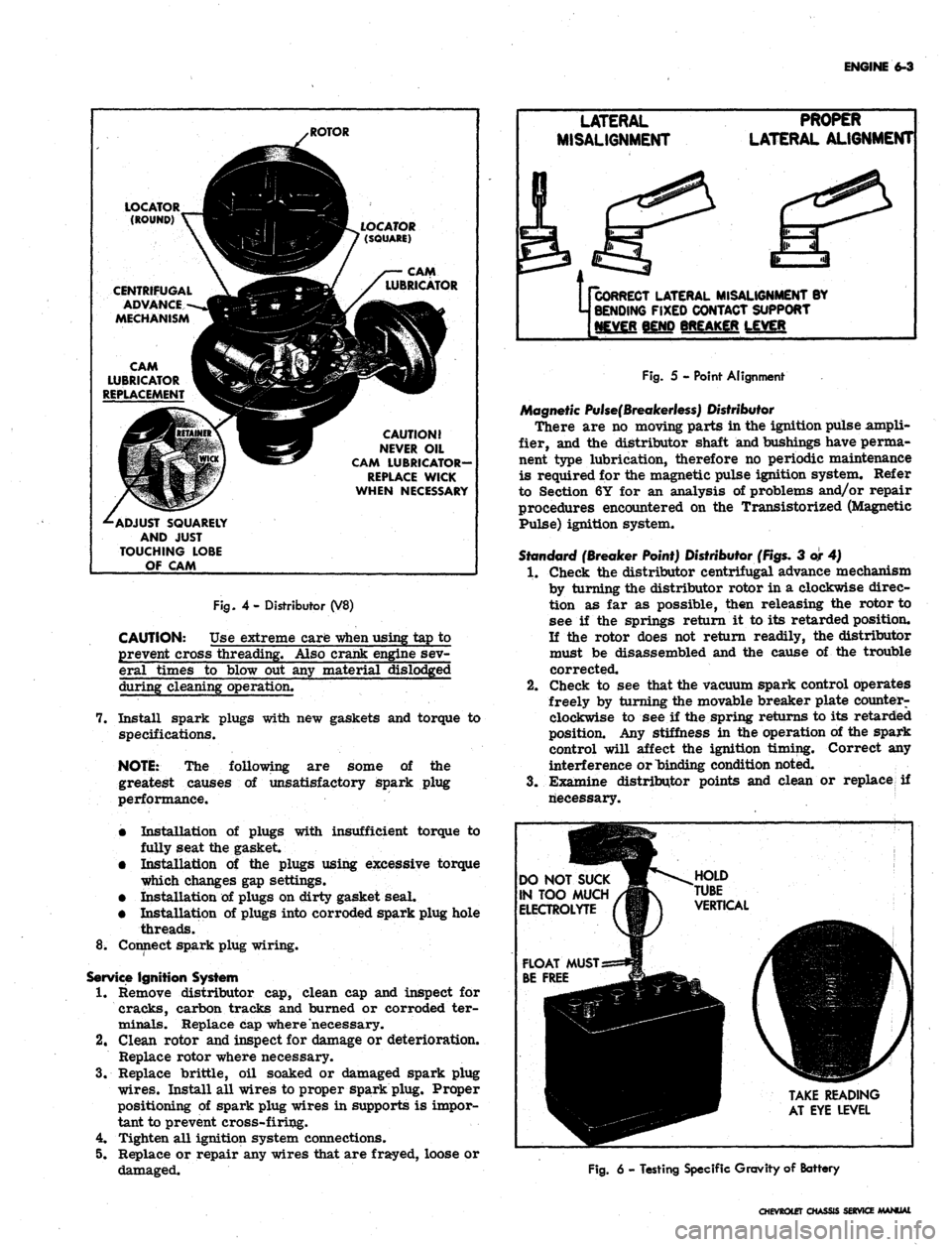
Fig.
4- Distributor (V8)
CAUTION: Use extreme care
-when
using tap to
prevent cross threading. Also crank engine sev-
eral times to blow out any material dislodged
during cleaning operation.
7. Install spark plugs with new gaskets and torque to
specifications.
NOTE:
The following are some of the
greatest causes of unsatisfactory spark plug
performance.
•
Installation of plugs with insufficient torque to
fully seat the gasket.
•
Installation of the plugs using excessive torque
which changes gap settings.
•
Installation of plugs on dirty gasket seal.
•
Installation of plugs into corroded spark plug hole
threads.
8^ Connect spark plug wiring.
Service
Ignition System
1.
Remove distributor cap, clean cap and inspect for
cracks, carbon tracks and burned or corroded ter-
minals. Replace cap where necessary.
2.
Clean rotor and inspect for damage or deterioration.
Replace rotor where necessary.
3.
Replace brittle, oil soaked or damaged spark plug
wires.
Install all wires to proper spark plug. Proper
positioning of spark plug wires in supports is impor-
tant to prevent cross-firing.
4.
Tighten all ignition system connections.
5. Replace or repair any wires that are frayed, loose or
damaged.
Us
CORRECT
LATERAL MISALIGNMENT BY
j BENDING
FIXED CONTACT SUPPORT
[NEVER
BEND BREAKER LEVER
Fig.
5 - Point Alignment
Magnetic
Pulse(Breakerless)
Distributor
There are no moving parts in the ignition pulse ampli-
fier, and the distributor shaft and bushings have perma-
nent type lubrication, therefore no periodic maintenance
is required for the magnetic pulse ignition system. Refer
to Section 6Y for an analysis of problems and/or repair
procedures encountered on the Transistorized (Magnetic
Pulse) ignition system.
Standard
(Breaker Point) Distributor
(Figs.
3 or 4)
1.
Check the distributor centrifugal advance mechanism
by turning the distributor rotor in a clockwise direc-
tion as far as possible, then releasing the rotor to
see if the springs return it to its retarded position.
If the rotor does not return readily, the distributor
must be disassembled and the cause of the trouble
corrected.
2.
Check to see that the vacuum spark control operates
freely by turning the movable breaker plate counter-
clockwise to see if the spring returns to its retarded
position. Any stiffness in the operation of the spark
control will affect the ignition timing. Correct any
interference or binding condition noted.
3.
Examine distributor points and clean or replace if
riecessary.
DO
NOT SUCK
IN
TOO MUCH
ELECTROLYTE
TAKE
READING
AT
EYE LEVEL
Fig.
6 - Testing Specific Gravity of Battery
CHEVROtET
CHASSIS SERVICE MANUAL
Page 277 of 659
ENGINE
6-12
ENGINE
MECHANICAL
IN LINE
INDEX
Page
General Description . „ 6-12
Component Replacement and Adjustment 6-12
.Engine Assembly 6-12
Removal 6-12
Installation 6-13
Manifold Assembly 6-14
Removal . 6-14
Installation 6-14
Rocker Arm Cover . 6-14
Removal 6-14
mstallation . . . 6-14
Valve Mechanism
......
1 6-14
Removal 6-14
Installation and Adjustment . 6-14
Valve Lifters
..............
6-15
Locating Noisy Lifters
„.;....
6-15
Removal
.'.*...•
6-15
Installation . 6-15
Valve Stem Oil Seal and/or Valve Spring . 6-16
Replacement . 6-16
Cylinder Head Assembly . 6-16
Removal 6-16
Installation . 6-16
Oil Pan . » 6-17
Removal . . . ; . . 6-17
Installation
.........
. 6-17
Oil Pump . 6-18
Page
Removal . 6-18
Installation . 6-18
Oil Seal (Rear Main) . 6-19
Replacement 6-19
Crankshaft Pulley and Hub 6-19
Removal 6-19
Installation 6-19
Torsional Damper 6-19
Removal 6-19
Installation 6-19
Crankcase Front Cover . 6-20
Removal . 6-20
Installation 6-20
•
Oil Seal (Front Cover) 6-20
Replacement 6-20
Camshaft 6-21
Measuring Lobe Lift . ... .
.-.••.-.
6-21
Removal 6-21
Installation 6-22
Timing Gears
..••••.............••• 6—22
Replacement
6-22
Flywheel
6-22
Removal
* 6-22
Installation
6-22
Engine
Mounts
6-23
Replacement
(Front)
6-23
Replacement
(Rear)
. 6-23
GENERAL DESCRIPTION
The
In
Line engines
(fig. 1L)
covered
in
this section
are
the 1H3 cu. in. L4, the 194,
230
and
250
cu. in. L6,
regardless
of
which passenger vehicle they
are
used
in.
This section covers
the
removal
and
installation
of en-
gine assemblies;
the
removal, installation
and
adjustment
of some sub-assemblies
and
replacement
of
some
com-
ponents.
For
service
to all
components
and
sub-assem-
blies (after removal)
and
removal
of
some sub-assem-
blies,
refer
to
Section
6 of the
Chassis Overhaul Manual.
Because
of the
interchangeability
and
similarity
of
many engine sub-assemblies
and
engine parts, regardless
of which passenger vehicle they
are
used
in,
typical illus-
trations
and
procedures
are
used except where specific
illustrations
or
procedures
are
necessary
to
clarify
the
operation. Although illustrations showing bench opera-
tions
are
used, most single operations, when
not
part
of a
general overhaul, should
be
performed
(if
practical) with
the engine
in the
vehicle.
COMPONENT REPLACEMENT
AND
ADJUSTMENT
ENGINE ASSEMBLY
Removal
1.
Drain cooling system
and
engine
oil.
2.
Remove
air
cleaner
and
disconnect battery cables
at 7.
battery.
3.
Remove hood
as
outlined
in
Section 11.
4.
Remove radiator
and
radiator shroud
as
outlined
in
Section 13.
5.
Remove
fan
blade
and
pulley
as
outlined
in
Section
6K.
6. Disconnect wires
at:
• Starter Solenoid
8.
• Delcotron
9.
Temperature Switch
Oil Pressure Switch
Coil
Disconnect:
Accelerator linkage
at
manifold bellerank.
Exhaust pipe
at
manifold flange.
.
Fuel line (from tank)
at
fuel pump.
Vacuum line
to
power brake unit
at
manifold
(if
so equipped).
• Power steering pump lines
at
pump
end (if so
equipped).
Raise vehicle
and
place
on
jack stands.
Remove propeller shaft.
CHEVROLET CHASSIS SERVICE MANUAL