fuel tank removal CHEVROLET CAMARO 1967 1.G Chassis Workshop Manual
[x] Cancel search | Manufacturer: CHEVROLET, Model Year: 1967, Model line: CAMARO, Model: CHEVROLET CAMARO 1967 1.GPages: 659, PDF Size: 114.24 MB
Page 277 of 659
ENGINE
6-12
ENGINE
MECHANICAL
IN LINE
INDEX
Page
General Description . „ 6-12
Component Replacement and Adjustment 6-12
.Engine Assembly 6-12
Removal 6-12
Installation 6-13
Manifold Assembly 6-14
Removal . 6-14
Installation 6-14
Rocker Arm Cover . 6-14
Removal 6-14
mstallation . . . 6-14
Valve Mechanism
......
1 6-14
Removal 6-14
Installation and Adjustment . 6-14
Valve Lifters
..............
6-15
Locating Noisy Lifters
„.;....
6-15
Removal
.'.*...•
6-15
Installation . 6-15
Valve Stem Oil Seal and/or Valve Spring . 6-16
Replacement . 6-16
Cylinder Head Assembly . 6-16
Removal 6-16
Installation . 6-16
Oil Pan . » 6-17
Removal . . . ; . . 6-17
Installation
.........
. 6-17
Oil Pump . 6-18
Page
Removal . 6-18
Installation . 6-18
Oil Seal (Rear Main) . 6-19
Replacement 6-19
Crankshaft Pulley and Hub 6-19
Removal 6-19
Installation 6-19
Torsional Damper 6-19
Removal 6-19
Installation 6-19
Crankcase Front Cover . 6-20
Removal . 6-20
Installation 6-20
•
Oil Seal (Front Cover) 6-20
Replacement 6-20
Camshaft 6-21
Measuring Lobe Lift . ... .
.-.••.-.
6-21
Removal 6-21
Installation 6-22
Timing Gears
..••••.............••• 6—22
Replacement
6-22
Flywheel
6-22
Removal
* 6-22
Installation
6-22
Engine
Mounts
6-23
Replacement
(Front)
6-23
Replacement
(Rear)
. 6-23
GENERAL DESCRIPTION
The
In
Line engines
(fig. 1L)
covered
in
this section
are
the 1H3 cu. in. L4, the 194,
230
and
250
cu. in. L6,
regardless
of
which passenger vehicle they
are
used
in.
This section covers
the
removal
and
installation
of en-
gine assemblies;
the
removal, installation
and
adjustment
of some sub-assemblies
and
replacement
of
some
com-
ponents.
For
service
to all
components
and
sub-assem-
blies (after removal)
and
removal
of
some sub-assem-
blies,
refer
to
Section
6 of the
Chassis Overhaul Manual.
Because
of the
interchangeability
and
similarity
of
many engine sub-assemblies
and
engine parts, regardless
of which passenger vehicle they
are
used
in,
typical illus-
trations
and
procedures
are
used except where specific
illustrations
or
procedures
are
necessary
to
clarify
the
operation. Although illustrations showing bench opera-
tions
are
used, most single operations, when
not
part
of a
general overhaul, should
be
performed
(if
practical) with
the engine
in the
vehicle.
COMPONENT REPLACEMENT
AND
ADJUSTMENT
ENGINE ASSEMBLY
Removal
1.
Drain cooling system
and
engine
oil.
2.
Remove
air
cleaner
and
disconnect battery cables
at 7.
battery.
3.
Remove hood
as
outlined
in
Section 11.
4.
Remove radiator
and
radiator shroud
as
outlined
in
Section 13.
5.
Remove
fan
blade
and
pulley
as
outlined
in
Section
6K.
6. Disconnect wires
at:
• Starter Solenoid
8.
• Delcotron
9.
Temperature Switch
Oil Pressure Switch
Coil
Disconnect:
Accelerator linkage
at
manifold bellerank.
Exhaust pipe
at
manifold flange.
.
Fuel line (from tank)
at
fuel pump.
Vacuum line
to
power brake unit
at
manifold
(if
so equipped).
• Power steering pump lines
at
pump
end (if so
equipped).
Raise vehicle
and
place
on
jack stands.
Remove propeller shaft.
CHEVROLET CHASSIS SERVICE MANUAL
Page 290 of 659
ENGINE 6-25
refer to Section 6 of the Chassis Overhaul Manual.
Because of the interchangeability and similarity of
many engines, engine sub-assemblies and engine parts,
regardless of which passenger vehicle they are used in,
typical illustrations and procedures are used except
where specific illustrations or procedures are necessary
to clarify the operation. Although illustrations showing
bench operations are used, most single operations, when
not part of a general overhaul, should be performed (if
practical) with the engine in the vehicle.
COMPONENT REPLACEMENT AND ADJUSTMENT
ENGINE ASSEMBLY
Removal
• .1. Drain cooling system and engine oil.
2.
Remove air cleaner and disconnect battery cables at
battery.
3.
Remove hood as outlined in Section 11.
4.
Remove radiator and shroud as outlined in Sec-
tion 13.
5. Remove fan blade and pulley as outlined in Sec-
tion 6K.
6. Disconnect wires at:
• Starter solenoid
• Delcotron
• Temperature switch
• Oil pressure switch
• Coil
7. Disconnect:
• Accelerator linkage at pedal lever.
• Exhaust pipes at manifold flanges.
• Vacuum line to power brake unit at manifold (if
so equipped),
• Power steering pump lines at pump end (if so
equipped).
• Fuel line (from tank) at fuel pump.
• Engine cooler lines (if so equipped).
• Oil pressure gauge line (if so equipped).
8. Raise vehicle and place on jack stands.
9. Remove propeller shaft.
NOTE:
If plug for propeller shaft opening
in transmission is not available, drain
transmission.
10.
Disconnect:
• Shift linkage at transmission.
• Speedometer cable at transmission.
• Transmission cooler lines (if so equipped).
11.
On synchromesh equipped vehicles, disconnect clutch
linkage at cross-shaft then remove cross-shaft en-
gine bracket.
12.
Remove rocker arm covers as outlined, then attach
engine lifting adapter at the proper cylinder head bolt
locations.
13.
Remove front mount bolts.
14.
Attach lifting device and raise engine to take weight
off front mounts, then remove rear mount bolts.
15.
Raise engine to take weight off rear mount, then re-
move crossmember.
NOTE:
On Chevrolets it will be necessary to
remove mount from transmission before cross-
member can be removed.
16.
Remove engine-transmission assembly from vehicle
as a unit.
17.
Remove transmission (and clutch):
Synchromesh Transmission
a. Remove clutch housing cover plate screws.
b.
Remove bolts attaching the clutch housing to en-
gine block then remove transmission and clutch
housing as a unit.
NOTE:
Support the transmission as the last
mounting bolt is removed, and as it is being
pulled away from the engine (to prevent damage
to clutch disc).
c. Remove starter and clutch housing rear cover
plate.
d. Loosen clutch mounting bolts a turn at a time (to
prevent distortion of clutch cover) until the spring
pressure is released. Remove all bolts, clutch
disc and pressure plate assembly.
Automatic
Transmission
a. Lower engine, secured by the hoist, and support
engine on blocks.
b.
Remove starter and converter housing underpan.
c. Remove flywheel-to-converter attaching bolts.
d. Support transmission on blocks.
e. Remove transmission-to-engine mounting bolts.
f. With the hoist attached, remove blocks from the
engine only and slowly guide the engine from the
transmission.
18.
Mount engine in stand.
Installation
1.
Attach lifting device to engine and remove engine
from engine stand.
2.
Install transmission (and clutch):
Synchromesh Transmission
a. Install the clutch on flywheel as outlined in Sec-
tion 7.
b.
Install clutch housing rear cover and starter.
c. Install transmission and clutch housing as out-
lined in Section 7.
d. Install clutch housing cover screws and tighten
securely.
Automatic
Transmissions
a. Position engine adjacent to the transmission and
align the converter with the flywheel.
b.
Bolt transmission to engine, then raise engine and
transmission assembly and install flywheel to
converter attaching bolts.
c. Install converter housing underpan and starter.
3.
Tilt and lower engine and transmission assembly into
the chassis as a unit, guiding engine to align front
mounts with frame supports.
4.
Install front mount bolts and torque to specifications.
5. Raise engine enough to install rear crossmember,
then install crossmember, install rear mount, lower
engine and torque rear mount to specifications.
CHEVROLET CHASSIS SERVICE MANUAL
Page 318 of 659
ENGINE FUEL
6M-10
the
two
"FILL71 lines
(fig.
6A). Refill whenever
the
level
falls below the lower
<'FILL"
line.
Storing Tool
When
the
tool
is
not used, fully depress
the
inner tube.
This seals
off
the
oil
reservoir from the vent hole
to pre-
vent
oil
loss
if
the tool
is
tipped.
Fig. 6A-Filling Tool with
Oil
FUEL PUMP
INDEX
Page
General Description
. . . . 6M-10
Service Procedures .6M-10
Inspection .6M-10
Page
Test
. . ; 6M-10
Removal
6M-11
Installation
6M-11
GENERAL DESCRIPTION
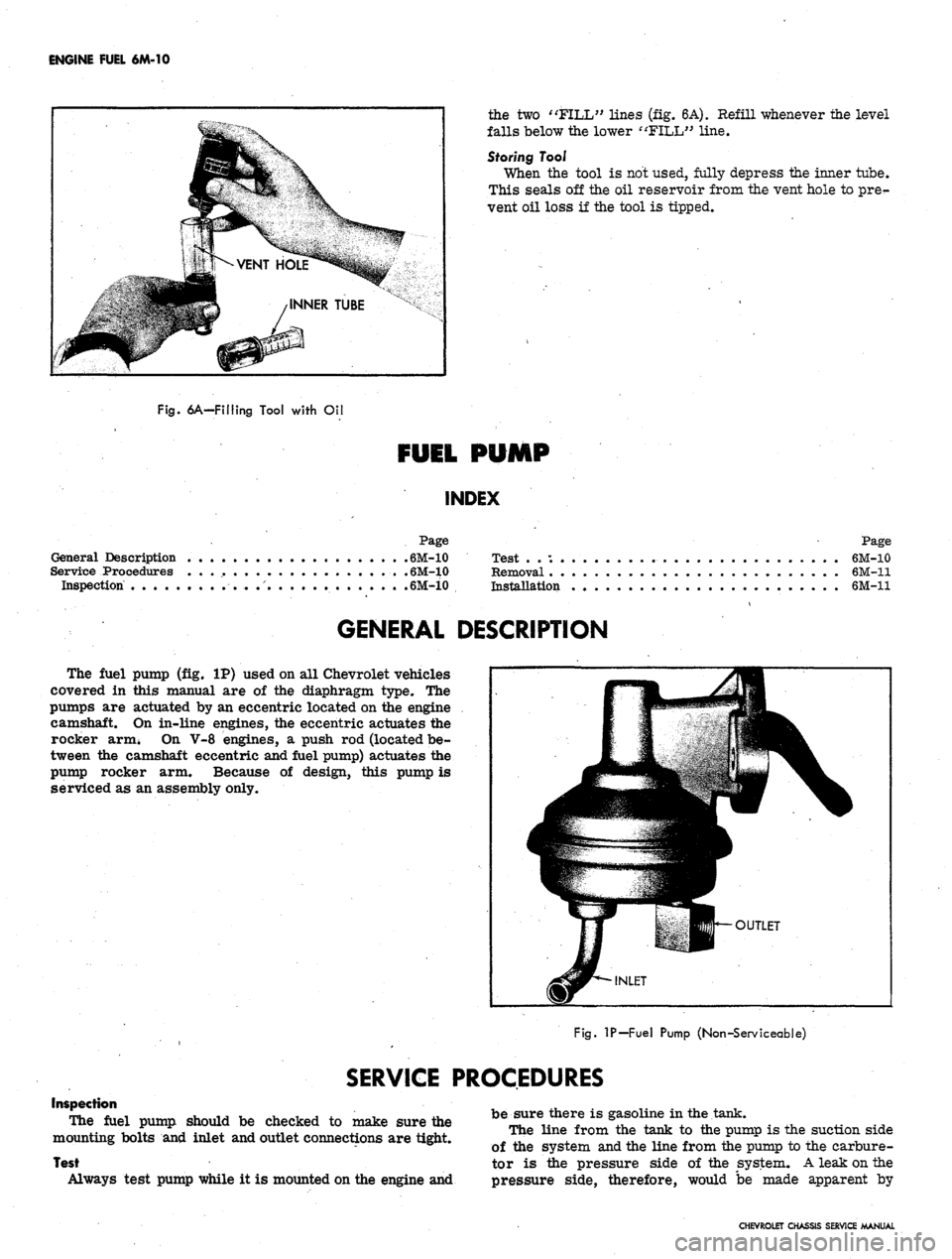
The fuel pump
(fig. IP)
used
on all
Chevrolet vehicles
covered
in
this manual
are of the
diaphragm type.
The
pumps
are
actuated
by an
eccentric located on
the
engine
camshaft.
On
in-line engines,
the
eccentric actuates
the
rocker arm*
On V-8
engines,
a
push
rod
(located be-
tween
the
camshaft eccentric and fuel pump) actuates
the
pump rocker
arm.
Because
of
design, this pump
is
serviced
as an
assembly only.
Fig.
IP—Fuel Pump (Non-Serviceable)
SERVICE PROCEDURES
Inspection
The fuel pump should
be
checked
to
make sure
the
mounting bolts
and
inlet and outlet connections
are
tight.
Test
Always test pump while
it is
mounted on the engine
and
be sure there
is
gasoline
in
the tank.
The line from
the
tank
to the
pump
is the
suction side
of
the
system and the line from the pump
to the
carbure-
tor
is the
pressure side
of the
system.
A
leak on
the
pressure side, therefore, would
be
made apparent
by
CHEVROLET CHASSIS SERVICE MANUAL
Page 319 of 659
ENGINE FUEL 6M-11
dripping fuel, but a leak on the suction would not be ap-
parent except for its effect of reducing volume of fuel on
the pressure side.
1.
Tighten any loose line connections and look for bends
or kinks in lines.
2.
Disconnect fuel pipe at carburetor. Disconnect dis-
tributor to coil primary wire so that engine can be
cranked without firing. Place suitable container at
end of pipe and crank engine a few revolutions. If
little or no gasoline flows from open end of pipe then
fuel pipe is clogged or pump is inoperative. Before
removing pump disconnect fuel pipe at gas tank and
outlet pipe and blow through them with an air hose
to make sure they are clear. Reconnect pipes and
retest while cranking engine.
CAUTION: Whenever the engine is cranked re-
motely at the starter, with a special jumper
cable or other means, the primary distributor
lead must be disconnected from the negative
post on the coil and the ignition switch must be
in the "ON" position. Failure to do this will
result in a damaged grounding circuit in the
ignition switch.
3.
If fuel flows from pump in good volume from pipe
at carburetor, check fuel delivery pressure to be
certain that pump is operating withint specified limits
as follows:
a. Attach a fuel pump pressure test gauge to dis-
connect end of pump to carburetor pipe.
b.
Run engine at approximately 450-1,000 rpm (on
gasoline in carburetor bowl) and note reading on
pressure gauge.
c. If pump is operating properly the pressure will
be within specifications and will remain constant
at speeds between 450-1,000 rpm. If pressure
is too low, too high, or varies materially at dif-
ferent speeds, the pump should be replaced.
Removal
1.
Disconnect fuel inlet and outlet pipes at fuel pump.
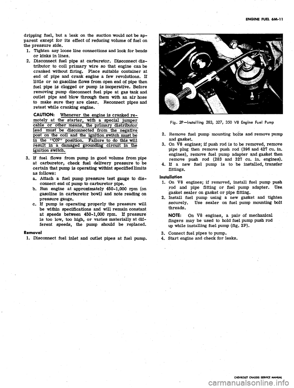
Fig.
2P-Installing 283, 327, 350 V8 Engine Fuel Pump
2.
Remove fuel pump mounting bolts and remove pump
and gasket.
3.
On V8 engines; if push rod is to be removed, remove
pipe plug then remove push rod (396 and 427 cu. in.
engines), remove fuel pump adapter and gasket then
remove push rod (283 and 327 cu. in. engines).
4.
If a new fuel pump is to be installed, transfer
fittings.
Installation
1.
On V8 engines; if removed, install fuel pump push
rod and pipe fitting or fuel pump adapter. Use.
gasket sealer on gasket or pipe fitting.
2.
Install fuel pump using a new gasket and tighten
securely. Use sealer on fuel pump mounting bolt
threads.
NOTE:
On V8 engines, a pair of mechanical
fingers may be used to hold fuel pump push rod
up while installing fuel pump (fig. 2P).
3.
Connect fuel pipes to pump.
4.
Start engine and check for leaks.
CHEVROLET CHASSIS SERVICE MANUAL
Page 409 of 659
FUEL TANK AND EXHAUST SYSTEMS 8-3
CAUTION: Always drain gasoline from com-
plete fuel system including carburetor, fuel
pump and all fuel lines and fuel tank if the vehi-
cle is to be stored for any appreciable length of
time. This precaution will prevent accumulation
of gum formation and resultant poor engine
performance.
Removal and Installation (Except Station Wagon)
1.
Drain fuel tank.
2.
Raise vehicle.
3.
Disconnect fuel pickup line, ground wire.
4.
Disconnect meter wire at rear harness connector.
5. Disconnect vent pipe hose.
6. Remove tank support straps and lower tank carefully.
7. To install, reverse the removal procedure.
Removal and Installation (Station Wagon)
1.
Drain fuel tank.
2.
Raise vehicle.
3.
Remove gas tank shield at the back of the left rear
wheel; remove all screws including the screw
attachment at the bottom of the quarter panel.
4.
Disconnect fuel pickup line and gauge wires from
tank unit.
5. Remove ground wire attaching bolt at body location.
6. Remove strap assembly nut and carefully lower tank.
7. Reverse removal procedure to install.
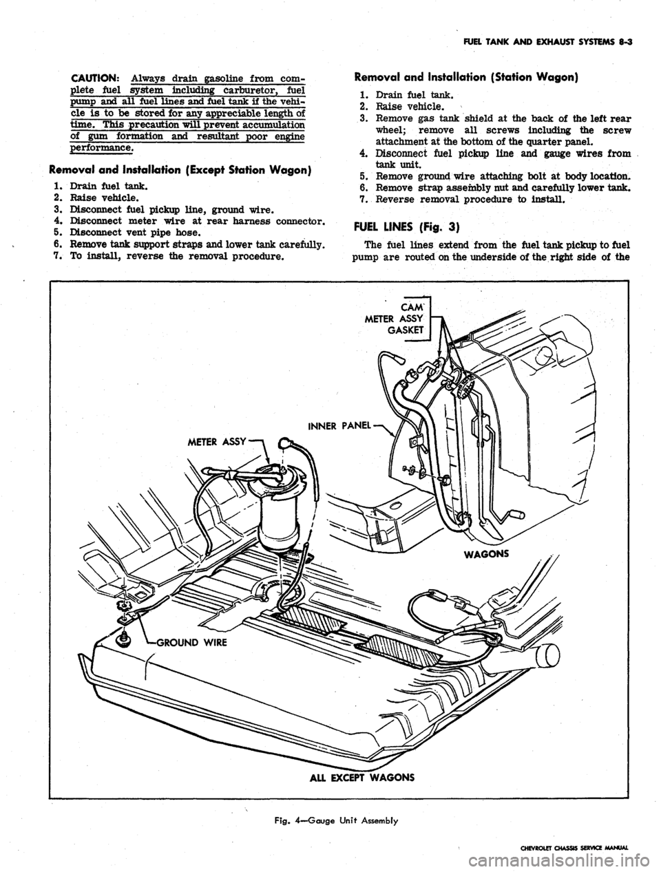
FUEL LINES (Fig. 3)
The fuel lines extend from the fuel tank pickup to fuel
pump are routed on the underside of the right side of the
CAM
METER ASSY
GASKET
METER ASSY
ALL EXCEPT WAGONS
Fig.
4—Gauge Unit Assembly
CHEVROLET CHASSIS SERVICE MANUAL
Page 410 of 659
FUEL TANK AND EXHAUST SYSTEMS 8-4
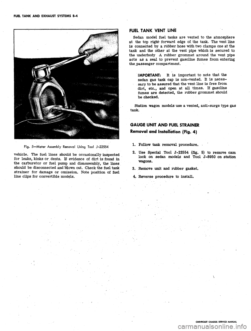
Fig.
5— Meter Assembly Removal Using Tool J-22554
vehicle. The fuel lines should be occasionally inspected
for leaks, kinks or dents. If evidence of dirt is found in
the carburetor or fuel pumto and disassembly, the lines
should be disconnected
and
blown out. Check the fuel tank
strainer for damage or omission. Note position of fuel
line clips for convertible models.
FUEL TANK VENT LINE
Sedan modei fuel tanks are vented to the atmosphere
at the top right- forward edge of. the tank. The vent line
is connected by a rubber hose with two clamps one at the
tank and the other at the vent pipe which is secured to
the underbody A rubber grommet around the vent pipe
acts as a seal to prevent gasoline fumes from entering
the.passenger compartment.
IMPORTANT: It is important to note that the
sedan gas tank cap is non-vented. It is neces-
sary to be assured that the vent line is free from
dirt, etc., and open at all times. If gasoline
fumes are detected, the rubber grommet should
be checked.
Station wagon models use a vented, anti-surge type gas
tank.
GAUGE UNIT AND FUEL STRAINER
Removal and Installation (Fig. 4)
1.
Follow tank removal procedure.
2.
Use Special Tool J-22554 (fig. 5) to remove cam
lock on sedan models and Tool J-8950 on station
wagons.
3.
Remove unit and rubber gasket.
4.
Reverse procedure to install.
CHEVROLET CHASSIS SERVICE MANUAL
Page 414 of 659
FUEL TANK AND EXHAUST SYSTEMS
8-8
CHEVELLE
FUEL TANKS
INDEX
Page
General Description.
g.g
Component Part Replacement
8-8
Fuel Tanks
. 8-8
Fuel Lines
8-8
Metering Units (Gauge, Sending Unit)
Fuel Tank Filler Neck Caps.
. .
Fuel Tank Vent Lines
Page
8-8
8-8
8-9
GENERAL DESCRIPTION
All models
use a 20
gallon capacity (approx.) fuel tank
mounted between
the
frame rails behind
the
rear axle.
The fuel tanks
are
basically
the
same
for
sedan, 2-seat
station wagon
and
pickup models except
for
filler neck
location
and
venting
(fig. 8).
All fuel tanks
are
vented
to the
atmosphere. Sedan
model tanks have
an
external vent hose and pipe assem-
bly
(fig. 11) and use a
non-vented fuel cap. Station wagon
and pickup model tanks
are
vented through
a
hose
and
vent pipe assembly
to the
filler neck
(fig. 8)
and
use a
vented, anti-surge type
gas cap. The
fuel caps
are two
different designs conforming
to SAE
standards
and are
not interchangeable.
The filler neck assembly
on
sedan models
is a
rear
fill design located behind
the
center
bar of the
bumper.
Station wagon
and
sedan pickup model filler neck assem-
blies
are
located
in
the left rear quarter panel.
The fuel pickup pipe
is
built integrally with
the
tank
gauge, located
at the
top-front center
of
the tank.
A
fine
mesh screen
is
located
at
the bottom-end
of the
fuel pick-
up pipe
to
prevent
the
entrance
of
foreign material into
the fuel system.
The sedan fuel tanks
are
held
in
place
by
two metal
straps attached individually
to the
underbody
at
each
end.
The straps hinge
at the
forward end and secure
the
tank
at
the
rear with
an
adjustable bolt
and nut
assembly.
The station wagon
and
pickup models have
a
frame
mounted fuel tank secured with straps
to
front and rear
supports.
COMPONENT PART REPLACEMENT
FUEL TANK
Draining Tank
The absence
of a
drain plug
in the gas
tanks makes
it
necessary
to
siphon fuel from
the
tank when draining
is
needed. Refer
to the
recommended draining procedures
previously outlined under Chevrolet Models
in
this
section.
Removal
and
Installation (Sedan Models)
1.
Raise vehicle.
2.
Drain fuel tank.
3.
Disconnect fuel pickup line
and
gauge wires from
tank unit.
4.
Disconnect vent hose from tank.
5. Remove tank support straps and lower tank carefully.
6.
To
install, reverse
the
removal procedure.
Removal
and
Installation
(Station Wagon
and
Pickup)
1.
Follow Steps
1
thru
3
outlined under sedan models.
2.
Remove tank support straps.
3.
Remove frame screw attachments from
the
front
support
(fig. 8).
4.
Guide tank forward
and
remove.
5.
To
install, reverse removal procedure.
FUEL LINES
The fuel lines, extending from fuel tank toiiuelpump,
are routed
on the
underside
of the
underbody along
the
right side
of the
vehicle opposite
the
single exhaust
sys-
tem.
The
fuel lines should occasionally
be
inspected
for
leaks,
kinks,
or
dents.
If
evidence
of
dirt
is
found
in the
carburetor
or
fuel pump
on
disassembly,
the
lines should
be disconnected
and
blown
out.
Check
the
fuel tank
strainer
for
damage
or
omission. Fuel lines
are of 5/16"
diameter tubing with beaded type ends
for
connections
of
hoses.
FUEL PIPE RETAINER
CUP
Removal
and
Installation
If fuel pipes
and
retainer clips
are
removed, Tool
J-7777 should
be
used
to
install
new
retainer clips
(fig.
10).
After removal
of the old
clip from
the
frame, position
the
new
clip
in the
location
of the old
clip. Index
the
"blind rivet"
and
press hard (hand pressure should
do)
to expand rivet.
GAUGE UNIT
AND
FUEL STRAINER
Removal
and
Installation
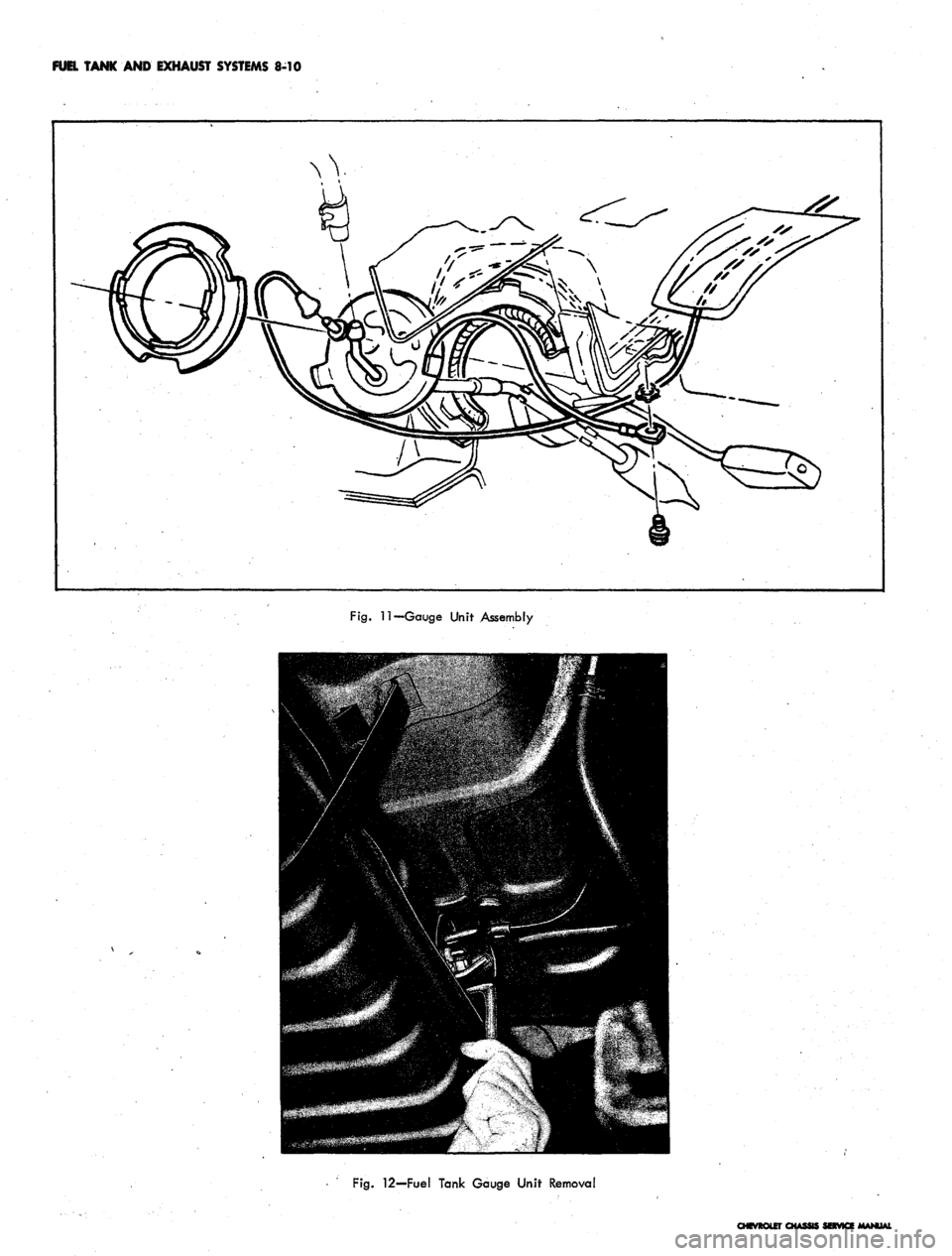
(Fig. 11)
1.
Drain tank
to a
level below
the
unit.
2.
Disconnect fuel pickup line
and
gauge unit wire.
3.
Use
special Tool J-8950
to
remove
cam
lock.
Re-
move unit
and
rubber gasket.
CAUTION: Carefully remove unit
so as not to
damage screen
on the end of
the pipe.
4.
Clean screen
by
blowing
out
with compressed
air.
5. Reverse procedure
to
install.
FUEL TANK FILLER NECK CAPS
The fuel tank filler neck caps
are
non-vented with
an
anti-surge feature. Station wagons have vented caps.
(Refer
to
"Fuel Tank Vent Lines").
CHEVROLET CHASSIS SERVICE MANUAL
Page 416 of 659
FUEL TANK
AND
EXHAUST SYSTEMS
8-10
Fig.
11—Gauge Unit Assembly
Fig.
12—Fuel Tank Gauge Unit Removal
CHEVROLET CHASSIS SERVICE
Page 419 of 659
FUEL TANK
AND
EXHAUST SYSTEMS
8-13
CHEVY II
FUEL TANKS
INDEX
Page
Page
General Description.
8-13
Component Part Replacement
8-13
Fuel Tanks
8-13
Fuel Lines
8-14
Metering Units (Gauge Sending Unit)
8-13
Fuel Tank Filler- Neck Caps.
. . 8-14
Fuel Tank Vent Lines .......
8-14
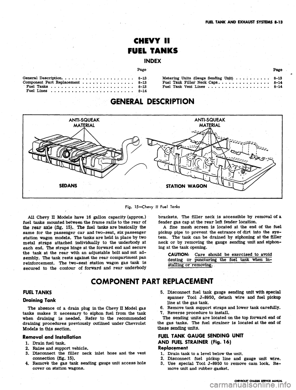
GENERAL DESCRIPTION
ANTI-SQUEAK
MA'
ANTI-SQUEAK
MATERIAL
SEDANS
STATION WAGON
Fig.
15-Chevy
II
Fuel Tanks
All Chevy
II
Models have
16
gallon capacity (approx.)
fuel tanks mounted between
the
frame rails
to the
rear
of
the rear axle
(fig. 15). The
fuel tanks
are
basically
the
same
for the
passenger
car
and two-seat,
six
passenger
station wagon models. The tanks
are
held
in
place
by two
metal straps attached individually
to the
underbody
at
each
end. The
straps hinge
at the
forward
end
and secure
the tank
at the
rear with
an
adjustable bolt and nut
ad-
sembly. The tank rests against the rear compartment
pan
reinforcement.
The
two-seat station wagon
gas
tank
is
secured
to the
contour
of
forward
and
rear underbody
brackets.
The
filler neck
is
accessible
by
removal
of a
fender
gas cap at the
rear left fender location.
A fine mesh screen
is
located
at the end of the
fuel
pickup pipe
to
prevent
the
entrance
of
dirt into
the sys-
tem.
The
tank
can be
drained
by
siphoning
at the
filler
neck
or by
removing
the
gauge sending unit and siphon-
ing
at the
tank opening.
CAUTION: Care should
be
exercised
to
avoid
denting
or
puncturing
the
fuel tank when
in-
stalling
or
removing.
~
COMPONENT PART REPLACEMENT
FUEL TANKS
Draining Tank
The absence
of a
drain plug
in
the Chevy
n
Model
gas
tanks makes
it
necessary
to
siphon fuel from
the
tank
when draining
is
needed. Refer
to the
recommended
draining procedures previously outlined under Chevrolet
Models
in
this section.
Removal
and
Installation
1.
Drain fuel tank.
2.
Raise
and
support vehicle.
3.
Disconnect
the
filler neck inlet hose
and the
vent
connection
(fig. 15).
4.
Remove
the gas
tank sending gauge unit access hole
cover
on
station wagons.
5. Disconnect fuel tank gauge sending unit with special
spanner Tool J-8950, detach wire
and
fuel pickup
line
at the gas
tank.
6. Remove tank support straps and lower tank carefully.
7. Reverse procedure
to
install.
The sending units
are
located on
the top
forward
end of
the
gas
tanks.
The
fuel strainer
is
located
at the end of
these sending units.
FUEL TANK GAUGE SENDING UNIT
AND FUEL STRAINER
(Fig. 16)
Replacement
1.
Drain tank
to a
level below
the
unit.
2.
Disconnect fuel pickup line
and
gauge unit wire.
3.
Use
special Tool J-8950
to
remove
cam
lock.
Re-
move unit and rubber gasket.
CHEVROLET CHASSIS SERVICE MANUAL
Page 424 of 659
FUEL TANK
AND
EXHAUST SYSTEMS
8-18
CORVETTE
FUEL TANK
INDEX
Page
General Description.
. 8-18
Service Operations
8-18
Fuel Tank
8-18
Gauge Sending Unit
8-20
Fuel Lines.
8-20
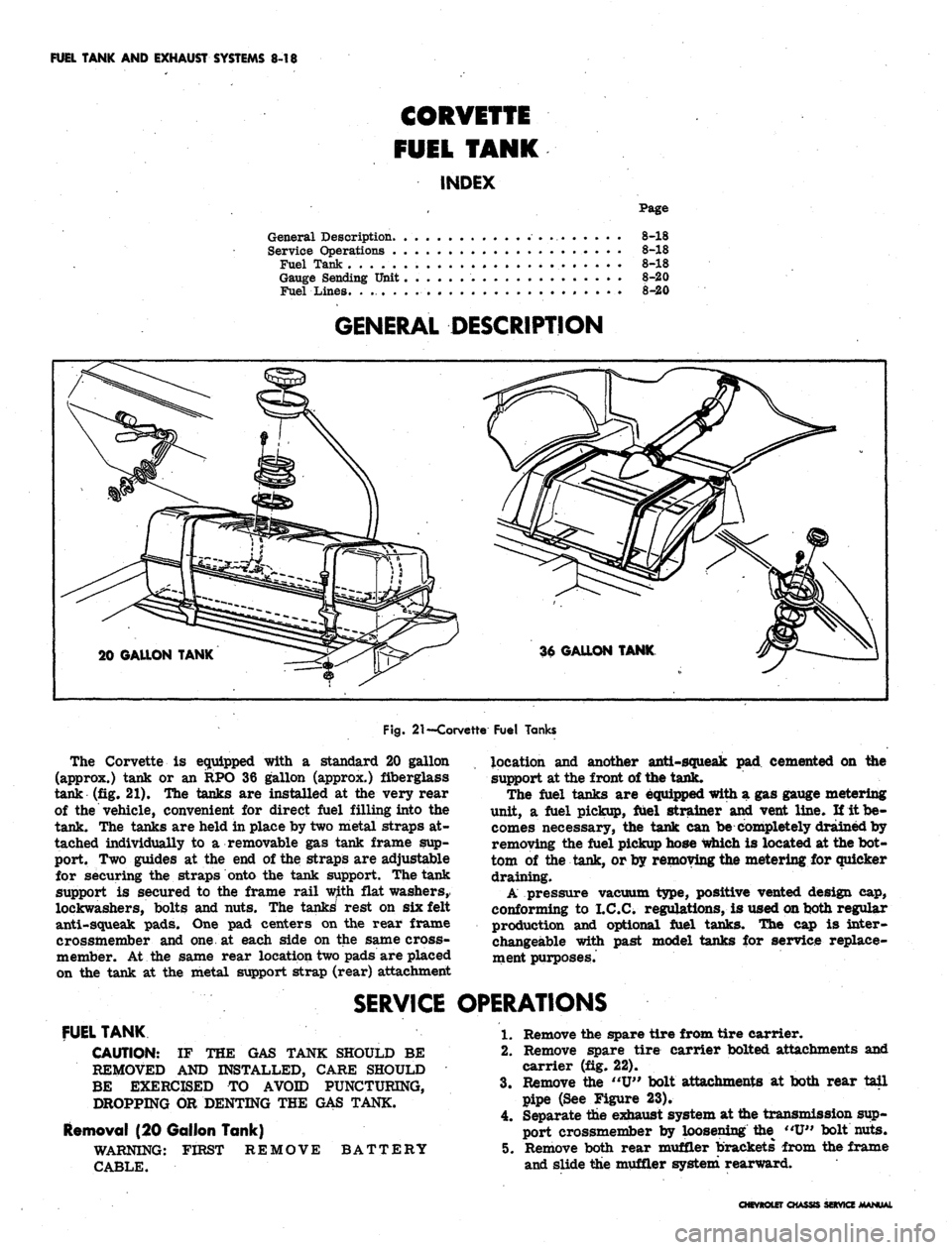
GENERAL DESCRIPTION
20 GALLON TANK
Fig.
21
—Corvette Fuel Tanks
The Corvette
is
equipped with
a
standard
20
gallon
(approx.) tank
or an RPO 36
gallon (approx.) fiberglass
tank
(fig. 21). The
tanks
are
installed
at the
very rear
of
the
vehicle, convenient
for
direct fuel filling into
the
tank.
The
tanks
are
held
in
place
by
two metal straps
at-
tached individually
to a
removable
gas
tank frame
sup-
port.
Two
guides
at the end of
the straps
are
adjustable
for securing
the
straps onto
the
tank support. The tank
support
is
secured
to the
frame rail with flat washers,
lockwashers, bolts
and
nuts.
The
tanks' rest
on six
felt
anti-squeak pads.
One pad
centers
on the
rear frame
crossmember
and one at
each side
on the
same cross-
member.
At the
same rear location two pads
are
placed
on
the
tank
at the
metal support strap (rear) attachment
location
and
another anti-squeak
pad
cemented
on the
support
at
the front
of
the tank.
The fuel tanks
are
equipped with
a gas
gauge metering
unit,
a
fuel pickup, fuel strainer
and
vent line.
If it be-
comes necessary,
the
tank
can be
completely drained
by
removing
the
fuel pickup hose which
is
located
at
the
bot-
tom
of the
tank,
or
by removing the metering
for
quicker
draining.
A pressure vacuum type, positive vented design
cap,
conforming
to
I.C.C. regulations,
is
used on both regular
production
and
optional fuel tanks.
The cap is
inter-
changeable with past model tanks
for
service replace-
ment purposes.
SERVICE OPERATIONS
FUEL TANK
CAUTION:
IF THE GAS
TANK SHOULD
BE
REMOVED
AND
INSTALLED, CARE SHOULD
BE EXERCISED
TO
AVOID PUNCTURING,
DROPPING
OR
DENTING
THE GAS
TANK.
Removal
(20
Gallon Tank)
WARNING: FIRST REMOVE BATTERY
CABLE.
1.
Remove
the
spare tire from tire carrier.
2.
Remove spare tire carrier bolted attachments
and
carrier
(fig. 22).
3.
Remove
the "U"
bolt attachments
at
both rear tail
pipe
(See
Figure
23).
4.
Separate
the
exhaust system
at
the transmission sup-
port crossmember
by
loosening
the "U"
bolt nuts.
5. Remove both rear muffler brackets from
the
frame
and slide
the
muffler system rearward.
CHEVROLET CHASSIS SERVICE MANUAL