gauges CHEVROLET CAMARO 1967 1.G Chassis Workshop Manual
[x] Cancel search | Manufacturer: CHEVROLET, Model Year: 1967, Model line: CAMARO, Model: CHEVROLET CAMARO 1967 1.GPages: 659, PDF Size: 114.24 MB
Page 52 of 659
HEATER AND AIR CONDITIONING 1A-29
time as possible will be required to perform the
operation. Don't leave the system open any longer
than is necessary.
• Finally, after the operation has been completed and
the system sealed again, air and moisture should be
evacuated from the system before recharging.
GAUGE SET
The gauge set (fig. 41) is used when purging, evacua-
ting, charging or diagnosing trouble in the system. The
gauge at the left is known as the low pressure gauge.
The face is graduated into pounds of pressure and, in
the opposite direction, in inches of vacuum. This is the
gauge that should always be used in checking pressures
on the low pressure side of the system. When all parts of
the system are functioning properly the refrigerant
pressure on the low pressure side never fails below 0
pounds pressure. However, several abnormal conditions
can occur that will cause the low pressure to fall into a
partial vacuum. Therefore, a low pressure gauge is
required.
The high pressure gauge is used for checking pres-
sures on the high pressure side of the system.
The connection at the left is for attaching the low
pressure gauge line and the one at the right the high
pressure gauge line. The center connector is common to
both and is for the purpose of attaching a line for adding
refrigerant, discharging refrigerant, evacuating the sys-
tem and other uses. When not required, this line or
connection should be capped.
NOTE:
Gauge fitting connections should be in-
stalled hand tight only and the connections leak
tested before proceeding.
The hand shutoff valves on the gauge manifold do not
control the opening or closing off of pressure to the
gauges. They merely close each opening to the center
connector and to each other. During most diagnosing
and service operation, the valves must be closed. The
only occasion for opening both at the same time would be
to bypass refrigerant vapor from the high pressure to
the low pressure side of the system, or in evacuating
both sides of the system.
CHARGING STATION
The J-8393 Charging Station is a portable assembly of
a vacuum pump, refrigerant supply, gauges, valves, and
most important, a five (5) pound metering refrigerant
charging cylinder. The use of a charging ey'inder elim-
inates the need for scales, hot water pails, etc.
The chief advantage of this unit is savings. A very
definite savings in refrigerant and time can be obtained
by using this unit. Since the refrigerant is metered into
the system by volume, the correct amount may be added
to.
the system and charged to the customer. This, coupled
with the fact that the unit remains "plumbed" at all times
and thus eliminates loss of refrigerant in purging of
lines and hooking-up, combines to enable the operator to
get full use of all refrigerant purchased by the
dealership.
All evacuation and charging equipment is hooked to-
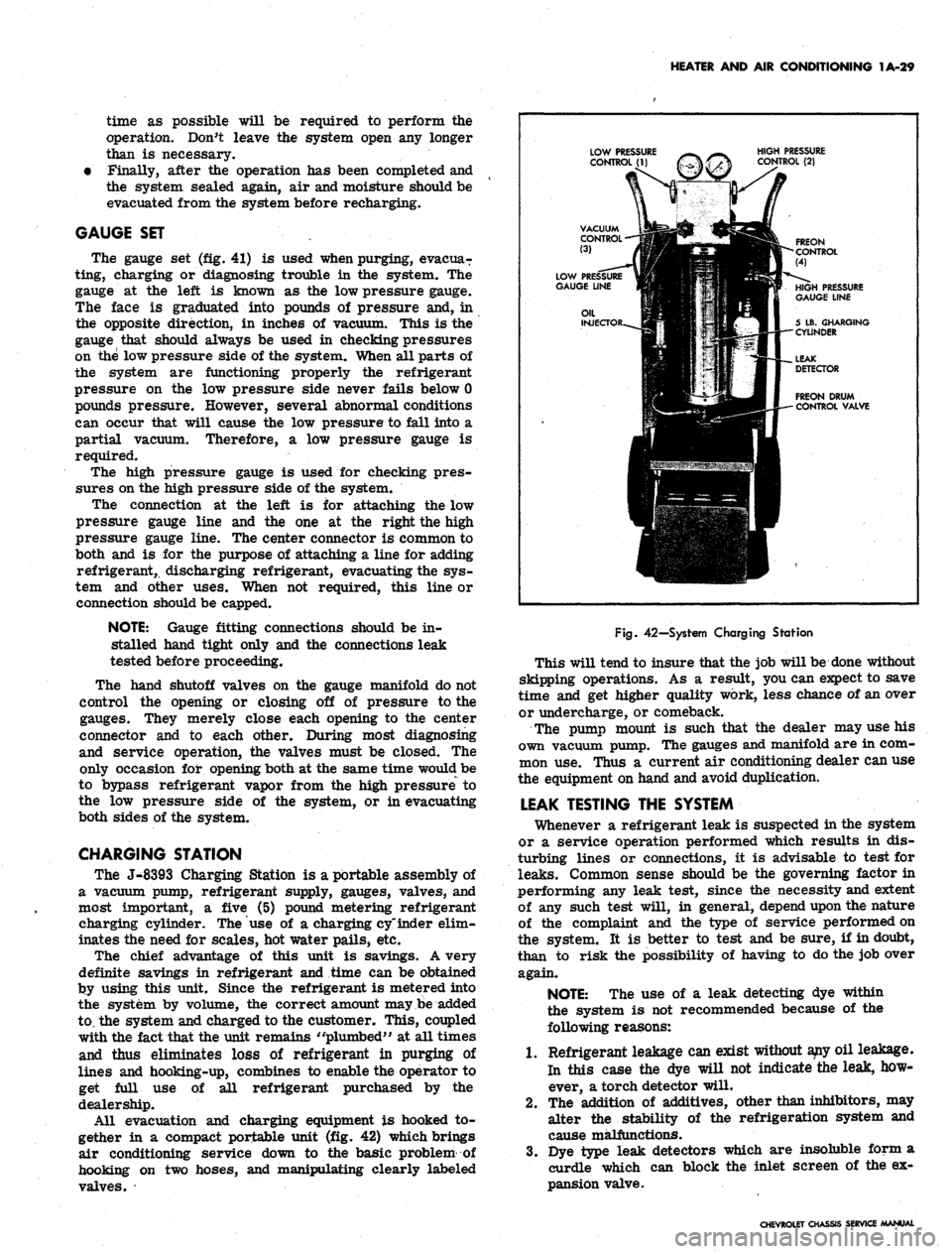
gether in a compact portable unit (fig. 42) which brings
air conditioning service down to the basic problem of
hooking on two hoses, and manipulating clearly labeled
valves.
Fig.
42—System Charging Station
This will tend to insure that the job will be done without
skipping operations. As a result, you can expect to save
time and get higher quality work, less chance of an over
or undercharge, or comeback.
The pump mount is such that the dealer may use his
own vacuum pump. The gauges and manifold are in com-
mon use. Thus a current air conditioning dealer can use
the equipment on hand and avoid duplication.
LEAK TESTING THE SYSTEM
Whenever a refrigerant leak is suspected in the system
or a service operation performed which results in dis-
turbing lines or connections, it is advisable to test for
leaks.
Common sense should be the governing factor in
performing any leak test, since the necessity and extent
of any such test will, in general, depend upon the nature
of the complaint and the type of service performed on
the system. It is better to test and be sure, if in doubt,
than to risk the possibility of having to do the job over
again.
NOTE:
The use of a leak detecting dye within
the system is not recommended because of the
following reasons:
1.
Refrigerant leakage can exist without any oil leakage.
In this case the dye will not indicate the leak, how-
ever, a torch detector will.
2.
The addition of additives, other than inhibitors, may
alter the stability of the refrigeration system and
cause malfunctions.
3.
Dye type leak detectors which are insoluble form a
curdle which can block the inlet screen of the ex-
pansion valve.
CHEVROLET CHASSIS SERVICE MANUAL
Page 66 of 659
HEATER AND AIR CONDITIONING 1A-43
LOW PRESSURE
CONTROL
HIGH PRESSURE
CONTROL
3
VACUUM
CONTROL
4
FREON
CONTROL
Fig,
56—Charging Station Controls
3.
When the pressure is reduced to below 100 pounds
on the high pressure gauge, open the low pressure
gauge valve and continue discharging until all re-
frigerant has been released. Close both gauge valves.
EVACUATING AND CHARGING THE SYSTEM
GENERAL NOTE: La all evacuating procedures
shown below, the specification of 26-28 inches
of Mercury vacuum is used. These figures are
only attainable at or near Sea Level Elevation.
For each 1000 feet above sea level where this
operation is being performed, the specifications
should be lowered by 1 inch. Example: at 5000
ft. elevation, only 21 to 23 inches of vacuum can
normally be obtained.
Whenever the air conditioning system is open for any
reason, it should not be put into operation again until it
has been evacuated to remove air and moisture which
may have entered the system.
The following procedures are based on the use of the
J-8393 Charging Station.
Filling Charging Cylinder
1.
Open control valve on refrigerant drum.
2.
Open valve on bottom of charging cylinder allowing
refrigerant to enter cylinder.
3.
Bleed cylinder valve on top (behind control panel) as
required to allow refrigerant to enter. When re-
frigerant reaches desired level (see "Air Condition-
ing System Capacities"), close valve at bottom of
cylinder and be certain bleed valve is closed
securely.
NOTE: It will be necessary to close bleed valve
periodically to allow boiling to subside to check
level in sight glass.
Installing Charging Station to System
1.
Be certain all valves on charging station are closed.
2.
Connect high pressure gauge line to high pressure
gauge fitting. (See "Installing Gauge Set to Check
System Operations.")
3.
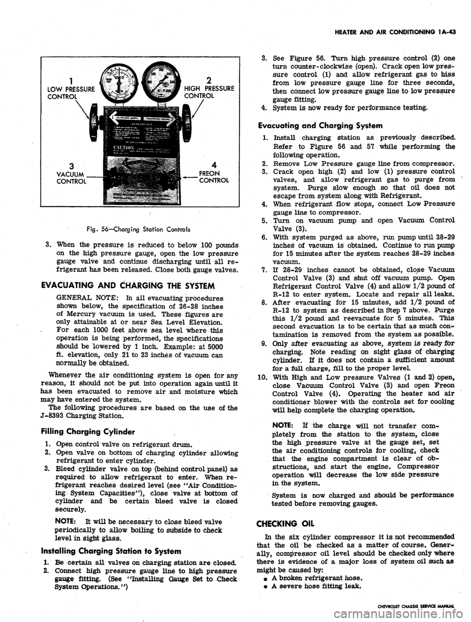
See Figure 56. Turn high pressure control (2) one
turn counter-clockwise (open). Crack open low pres-
sure control (1) and allow refrigerant gas to hiss
from low pressure gauge line for three seconds,
then connect low pressure gauge line to low pressure
gauge fitting.
4.
System is now ready for performance testing.
Evacuating and Charging System
1.
Install charging station as previously described.
Refer to Figure 56 and 57 while performing the
following operation.
2.
Remove Low Pressure gauge line from compressor.
3.
Crack open high (2) and low (1) pressure control
valves, and allow refrigerant gas to purge from
system. Purge slow enough so that oil does not
escape from system along with Refrigerant.
4.
When refrigerant flow stops, connect Low Pressure
gauge line to compressor.
5.
Turn on vacuum pump and open Vacuum Control
Valve (3).
6. With system purged as above, run pump until 28-29
inched of vacuum is obtained. Continue to run pump
for 15 minutes after the system reaches 28-29 inches
vacuum.
7.
If 28-29 inches cannot be obtained, close Vacuum
Control Valve (3) and shut off vacuum pump. Open
Refrigerant Control Valve (4) and allow 1/2 pound of
R-12 to enter system. Locate and repair all leaks.
8. After evacuating for 15 minutes, add 1/2 pound of
R-12 to system as described in Step 7 above. Purge
this 1/2 pound and reevacuate for 5 minutes. This
second evacuation is to be certain that as much con-
tamination is removed from the system as possible.
9. Only after evacuating as above, system is ready for
charging. Note reading on sight glass of charging
cylinder. If it does not contain a sufficient amount
for a full charge, fill to the proper leveL
10.
With High and Low pressure Valves (1 and 2) open,
close Vacuum Control Valve (3) and open Freon
Control Valve (4). Operating the heater and air
conditioner blower with the controls set for cooling
will help complete the charging operation.
NOTE: If the charge will not transfer com-
pletely from the station to the system, close
the high pressure valve at the gauge set, set
the air conditioning controls for cooling, check
that the engine compartment is clear of ob-
structions, and start the engine. Compressor
operation will decrease the low side pressure
in the system.
System is now charged and should be performance
tested before removing gauges.
CHECKING OIL
In the six cylinder compressor it is not recommended
that the oil be checked as a matter of course. Gener-
ally, compressor oil level should be checked only where
there is evidence of a major loss of system oil such as
might be caused by:
• A broken refrigerant hose.
• A severe hose fitting leak.
CHEVROLET CHASSIS SERVICE MANUAL
Page 273 of 659
ENGINE
6-8
Check
and
Adjust Ignition Timing
(Fig. 13)
1.
Disconnect
the
distributor spark advance hose
and
plug
the
vacuum source opening.
2.
Start engine
and run at
idle speed
(see
tune
up
chart).
3.
Aim
timing light
at
timing
tab.
NOTE:
- The
markings
on the
tabs
are in 2°
increments
(the
greatest number
of
markings
on
the
"A"
side
of the "O"). the "O"
markings
is
TDC
of
#1 cylinder
and all
BTDC settings fall
on
the
"A"
(advance) side
of "O".
4.
Adjust
the
timing
by
loosening
the
distributor clamp
and
,
rotating
the
distributor body
as
required, then
tighten
the
clamp.
5.
Stop engine
and
remove timing light
and
reconnect
the spark advance hose.
Adjust Idle Speed
and
Mixture
(Fig. 14)
(Except when
equipped with
Air
Injection Reactor System)
1.
As a
preliminary adjustment, turn idle mixture
screws lightly
to
seat
and
back
out 2
turns.
CAUTION:
Do not
turn idle mixture screw
tightly against seat
or
damage
may
result.
2.
With engine running
at
operating temperature (choke
wide open) adjust idle speed screw
to
bring idle
speed
to
specified
rpm
(automatic transmission
in
drive, manual transmission
in
neutral).
3.
Adjust idle mixture screw
to
obtain highest steady
idle speed
(1/4
turn
out
from lean roll).
4.
Repeat Steps
2 and 3 as
needed
for
final adjustment.
5.
Shut down
the
engine, remove gauges
and
install
air
cleaner.
Adjust Idle Speed
and
Mixture
(Fig. 14)
(With
Air
Injection Reactor System)
The recommended adjustment procedure
for Air
Injec-
tion Reactor System equipped engines
is as
follows:
1.
As a
preliminary adjustment, turn idle mixture
screws lightly
to
seat
and
than back
out 3
turns.
CAUTION:
Do not
turn idle mixture screw
tightly against seat
or
damage
may
result.
2.
With engine running
at
operating temperature, choke
wide open,
and
parking brake applied, adjust idle
specified idle speed (automatic
"drive"-manual transmission
in
to
in
screw
transmission
"neutral").
;3.
Adjust idle mixture screw (turn
in) to
"lean roll"
position; then turn screw
out 1/4
turn
(1/4
turn rich
from "lean roll").
The
definition
of
"lean roll" point
is
a 20 to 30 rpm
drop
in
engine speed, obtained
by
leaning
the
idle mixture.
4.
Repeat Steps
2 and 3 as
needed
for
final adjustments.
ADDITIONAL CHECKS
AND
ADJUSTMENTS
Testing Crankcase Ventilation Valve
(Fig. 15) 0
1.
Connect tachometer
and
vacuum gauge
as for
idle
speed
and
mixture adjustment.
2.
Set
parking brake, start engine
and
adjust idle speed
and mixture.
3.
Disconnect ventilation hose
at
valve, block opening
of
valve
and
read engine
rpm
change.
4.
A
change
of
less than
50 rpm
indicates
a
plugged
ventilation valve
-
replace
the
valve.
Cylinder Balance Test
(Fig. 16)
It
is
often difficult
to
locate
a
weak cylinder.
A com-
pression test,
for
example, will
not
locate
a
leaky intake
manifold,
a
valve
not
opening properly
due to a
worn
camshaft,
or a
defective spark plug.
With
the
cylinder balance test,
the
power output
of one
cylinder
may be
checked against another, using
a set of
grounding leads. When
the
power output
of
each cylinder
is
not
equal,
the
engine will lose power
and run
roughly.
Perform
a
cylinder balance test
as
follows:
1.
Connect
the
tachometer
and
vacuum gauge.
2.
Start engine
and run at 1500 rpm.
3.
Ground large clip
of
grounding leads
and
connect
in-
dividual leads
to all
spark plugs except
the
pair being
tested.
Divide
the
firing order
in
half
and
arrange
one
half
over
the
other.
The
cylinders
to be
tested together
ap-
pear
one
over
the
other.
L4 Firing Order
V8 Firing Order
1-8-4-3-6-5-7-2
1-6, 8-5, 4-7, 3-2
1-3-4-2
= 1-3
4-2
L6 Firing Order
1-5-3-6-2-4
=
=
1-4. 3-2
1-5-3
6-2-4
1-6, 5-2, 3-4
1-8-4-3
6-5-7-2
4.
Operate engine
on
each pair
of
cylinders
in
turn
and
note engine
rpm and
manifold vacuum
for
each pair.
A variation
of
more than
1
inch
of
vacuum
or 40 rpm
between pairs
of
cylinders being tested indicates that
the cylinders
are off
balance.
Battery
The battery should
be
checked with special testing
equipment
and to the
equipment manufacturers specifica-
tions.
See
Section 6Y
for
complete information
on
battery
tests.
Ignition
The following additional ignition checks
may be
made
with
any of
several pieces
of
equipment available
for un-
covering
the
source
of
engine difficulties.
The
specific
operating instructions
of the
equipment manufacturer
should
be
followed:
Cranking voltage
Ignition switch
Distributor resistance
Secondary resistance
Ignition output
and
secondary leakage
Cranking Voltage
(Fig. 17)
1.
Disconnect coil primary lead
at the
coil negative
terminal
to
prevent engine from firing during
cranking.
2.
Connect voltmeter between primary terminal
of coi|
(resistance wire side)
and
ground.
3.
Operate starting motor.
CHEVROLET CHASSIS SERVICE MANUAL
Page 309 of 659

SECTION 6M
ENGINE FUEL
CONTENTS OF THIS SECTION
Page
Carburetors 6M-1 Fuel Pumps .
Air Cleaners 6M-7 Special Tools
Page
6M-10
6M-12
CARBURETORS
INDEX
Page
General Description 6M-1
Service Procedures 6M-1
Preliminary Checks 6M-1
Idle Speed and Mixture Adjustment ........... 6M-1
Fast Idle Adjustment .................. 6M-3
Choke Adjustment 6M-3
Float Adjustment 6M-4
Page
Additional Adjustments 6M-4
Removal 6M-4
Test Before Installation 6M-5
Installation 6M-5
Fuel Filter Maintenance 6M-5
Choke Coil Replacement 6M-5
Throttle Linkage Adjustment . . 6M-6
GENERAL DESCRIPTION
Various carburetors (fig. lc) are used with Chevrolet,
Chevelle, Chevy II, Camaro and Corvette passenger
vehicles. These carburetors are designed to meet the
particular requirements of engines, transmissions and
vehicles, therefore carburetors that look alike are not
always interchangeable. (Refer to carburetor part num-
ber and/or specifications.)
Because many service procedures for the various
carburetors are similar, typical illustrations and pro-
cedures are used except where specific illustrations or
procedures are necessary to clarify the operation.
This section covers removal, installation and adjust-
ments (on engine) of carburetors. Also covered in this
section are maintenance procedures for choke coils,
throttle linkage and fuel filters. For carburetor .over-
haul procedures and additional adjustments (bench), re-
fer to Section 6M of the Overhaul Manual under the
carburetor being serviced.
Specifications for carburetors are located in the back
of this manual.
SERVICE PROCEDURES
Preliminary Checks
1.
Thoroughly warm-up engine. If the engine is cold,
allow to run for at least 15 minutes.
2.
Inspect torque of carburetor to intake manifold bolts
and intake manifold to cylinder head bolts to exclude
the possibility of air leaks.
3.
Inspect manifold heat control valve (if used) for free-
dom of action and correct spring tension.
Idle Speed and Mixture Adjustment (Except Air Injection
Reactor System)
NOTE:
This adjustment should be performed
with engine at operating temperature and park-
ing brake applied.
1.
Remove Air Cleaner.
2.
Connect tachometer and vacuum gauge to engine, then
set hand brake and shift transmission into neutral.
3.
As a preliminary adjustment, turn idle mixture
screws lightly to seat and back out 1-1/2 turns.
CAUTION: Do not turn idle mixture screw
tightly against seat or damage may result.
4.
With engine running (choke wide open) adjust idle
speed screw to specified idle speed, (automatic
transmission in drive, synchronized transmission in
neutral).
5. Adjust idle mixture screw to obtain highest steady
vacuum at specified idle speed.
NOTE:
On air conditioned vehicles, turn air
conditioning to the "on" position and hold the
hot idle compensator valve closed while adjust-
ing idle speed and idle mixture screws.
NOTE:
On Rochester BV carburetors the idle
mixture screw should be turned out 1/4 turn
from the "lean roll" position. The definition
of "lean roll" point is a 20 to 30 rpm drop
in engine speed obtained by leaning the idle
mixture.
6. Repeat Steps 4 and5 as needed for final adjustment.
NOTE:
If necessary, final adjustment of the \
carburetor may be made with the air cleaner
installed.
7. Turn engine off, remove gauges and install air
clearer.
CHEVROLET CHASSIS SERVICE MANUAL
Page 311 of 659

ENGINE FUEL 6M-3
Idle Speed and Mixture Adjustment (With Air Injection
Reactor System)
The following is the recommended procedure for Air
Injection Reactor System equipped engines.
NOTE: This adjustment should be performed
with engine at operating temperature and parking
brake applied.
1.
Remove air cleaner.
2.
Connect tachometer to engine, then set hand brake
and shift transmission into neutral.
3.
As a preliminary adjustment, turn idle mixture
screws lightly to seat and back out 3 turns.
CAUTION: Do not turn idle mixture screw
tightly against seat or damage may result."
4.
With engine running (choke wide open) adjust idle
speed screw to specified idle speed. (Automatic
transmission in dirve, synchronized transmission in
neutral).
5.
Adjust idle mixture screw (turn in) to "lean roll"
position; then turn screw out 1/4 turn (1/4 turn
rich from "lean roll"). The definition of "lean
roll" point is a 20 to 30 rpm drop in engine speed,
obtained by leaning the idle mixture.
NOTE: On air conditioned vehicles, turn air
conditioning "OFF" on in-line, 283, 327, and'
350 cu. in. engines, and turned "ON" and hot
idle compensator held closed on 396 and 427 cu.
in. engines.
6. Repeat Steps 4 and 5 as needed for final adjustment.
NOTE: If necessary, final adjustment of the
carburetor may be made with air cleaner
installed.
7.
Shut down the engine, remove gauges and install air
cleaner. *
Fast Idle Adjustment
Rochester
4MV and Holley
With fast idle lever on high step of cam and choke valve
open (engine warm) set fast idle to give specified engine
rpm. Adjust sejrew on Rochester 4MV and bend fast
idle lever *pn Holley. .
Choke Adjustment
With Remote Choke (Fig. 2c)
1.
Remove air cleaner and check to see that choke
valve and rod move freely.
2.
Disconnect choke rod at choke lever.
3.
Check choke adjustment as follows:
On all except 275 and 300 h.p. 327 cu. in. engines,
hold choke valve closed and pull.rod up against stop.
The top of choke rod end should be 1/2-1 rod diame-
ter above top of hole in choke valve lever.
On 275 and 300 h.p. 327 cu. in. engines, hold choke
valve closed and push rod down against stop on ther-
mostat bracket. The top of the choke rod should be
1/2-1 rod diameter below the top of the hole in the
choke lever.
4.
If necessary, adjust rod length by bending rod at
offset bend. (Bend must be such that rod enters
choke lever hole freely and squarely).
5.
Connect rod at choke lever and install air cleaner.
With Manual Choke (Carter YF)
1.
Remove air cleaner.
CHOKE VALVE
COMPLETELY
CLOSED
PULL UPWARD ON
ROD TO END OF
TRAVEL
BEND ROD
TO ADJUST
ROD IN BOTTOM
OF SLOT
BOTTOM OF
ROD SHOULD
BE EVEN WITH
TOP OF
HOLE
CHOKE VALVE
CLOSED
BOTTOM OF
ROD SHOULD
BE EVEN WITH
TOP OF HOLE
TOP OF ROD
SHOULD BE EVEN
WITH BOTTOM
OF HOLE (CHOKE
CLOSED)
BEND ROD TO
ADJUST
PULL DOWNWARD'
ON ROD TO CON-
TACT STOP
L6 (TYPICAL)
[
V8 327-275 HP
V8 350-295 HP
BEND ROD
TO ADJUST
PULL UPWARD ON
ROD TO CONTACT
STOP ON BRACKET
ALL V8 (EXCEPT 327-275 HP
AND 350-295 HP)
Fig.
2C—Remote Choke Adjustment
CHEVROLET CHASSIS SERVICE MANUAL
Page 392 of 659
CLUTCH AND TRANSMISSIONS 7-33
from rolling. The pointer on the indicator quadrant
should line up properly with the range indicators in all
ranges.
OIL LEAKS
Before attempting to correct an oil leak, the actual
source of the leak must be determined. In many cases
the source of the leak can be deceiving due to "wind flow1 f
around the engine and transmission.
The suspected area should be wiped clean of all oil
before inspecting for the source of the leak. Red dye is
used in the transmission oil at the assembly plant and
will indicate if the oil leak is from the transmission.
The use of a "black light"* to identify the oil at the
source of leak is also helpful. Comparing the oil from
the leak to that on the engine or transmission dip stick
(when viewed by black light) will determine the source
of the leak.
Oil leaks around the engine and transmission are gen-
erally carried toward the rear of the car by the air
stream. For example, a transmission "oil filter tube
to case leak" will sometimes appear as a leak at the
rear of the transmission. In determining the source of
an oil leak it is most helpful to keep the engine running.
The mating surfaces of servo cover, converter housing,
transmission case and transmission case extension
should be carefully examined for signs of leakage. The
vacuum modulator must also be checked to insure that
the diaphragm has not ruptured as this would allow trans-
mission oil to be drawn into the intake manifold. Us-
ually, the exhaust will be excessively smoky if the
diaphragm ruptures due to the transmission oil added to
the combustion. The transmission case extension rear
oil seal should also be checked. All test plugs should be
checked to make sure that they are tight and that there
is no sign of leakage at these points. The converter
underpan should also be removed. Any appreciable quan-
tity of oil in this area would indicate leakage at the pump
square seal ring, pump seal assembly, or pump bolt
sealing washers.
BASIC PRESSURE CHECKS
Four basic pressure checks are used for diagnosis and
operational checks for the Aluminum Powerglide trans-
mission. All checks should be made only after thoroughly
warming up the transmission.
• Wide Open Throttle Upshift Pressure.
• Idle Pressure in "Drive" Range.
• Manual "Low" Range Pressure.
• "Drive" Range Overrun (Coast) Pressure.
It is not recommended that stall tests be conducted
which would result in engine vacuum falling below 10" Hg.
Pressure gauge hose connections should be made at
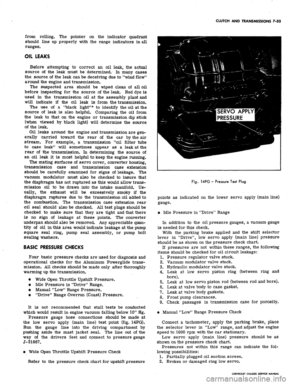
the low servo apply (main line) test point (fig. 14PG).
Run the gauge line into the driving compartment by
pushing aside the mast jacket seal. The line out of the
way of the drivers feet and connect to pressure gauge
J-21867.
• Wide Open Throttle Upshift Pressure Check
Refer to the pressure check chart for upshift pressure
SERVO APPLY
PRESSURE
Fig.
14PG - Pressure Test Plug
points as indicated on the lower servo apply (main line)
gauge.
• Idle Pressure in "Drive" Range
In addition tp the oil pressure gauges, a vacuum gauge
is needed for this check.
With the parking brake applied and the shift selector
lever in "Drive", low servo apply (main line) pressure
should be as shown on the pressure check chart.
If pressures are not within these ranges, the following
items should be checked for oil circuit leakage:
1.
Pressure regulator valve stuck.
2.
Vacuum modulator valve stuck.
3.
Hydraulic modulator valve stuck.
4.
Leak at low servo piston ring (between ring and
bore).
5.
Leak at low servo piston rod (between rod and bore).
6. Leak at valve body to case gasket.
7.
Leak at valve body gaskets.
8. Front pump clearances.
9. Check passages in transmission case for porosity.
• Manual "Low" Range Pressure Check
Connect a tachometer, apply the parking brake, place
the selector lever in "Low" range, and adjust the engine
speed to 1000 rpm with the car stationary.
Low servo apply (main line) pressure should be as
shown on the pressure check chart.
Pressures not within this range can indicate the fol-
lowing possibilities:
1.
Partially plugged oil suction screen.
2.
Broken or damaged ring low servo.
CHEVROLET CHASSIS SERVICE MANUAL
Page 513 of 659
SECTION 12
ELECTRICAL-BODY AND CHASSIS
CONTENTS
OF
THIS
SECTION
Page
Page
System 12-1
Instruments and Gauges 12-21
Directional Signal 12r40
Windshield Wipers and Washers 12-44
Wiring Diagrams 12-56
Special Tools 12-60
LIGHTING SYSTEM
INDEX
Page
General Description
!2-i
Maintenance and Adjustments
•.................. 12-2
Headlamp Adjustment......................
12-3
Headlamp Panel Travel Adjustment.
12-5
Service Operations.
. . .. 12-5
Front Lighting
12-5
Headlamp
. 12_5
Parking Lamp
12-5
Fender Lamp
. 12_^
Headlamp Panel
12-8
Headlamp Panel Motor
^2-9
Rear Lighting
l2-10
Tail, Stop and Directional Lamps
12-10
Page
Backing Lamps
12-14
License Plate Lamp
12-14
Automatic Transmission Quadrant Lamp
12-14
Seat Separator Console Lamps
. 12-15
Lighting Switch
. . 12-15
Wiper Switch.
12-15
Stoplight Switch
12-15
Dimmer Switch
12-15
Backing Lamp Switches
12-15
Neutral Safety Switches
12-17
Parking Brake Alarm Switch
................. 12-19
Instrument Panel Compartment Lamp/Switch
12-19
Cirgarette Lighter
12-19
GENERAL DESCRIPTION
.
The lighting system includes: the main lighting switch,
stop light, dimmer, and backing lamp switches, head-
lamps, parking lamps, stop, tail and directional lamps,
instrument illumination and indicator lamps, and the
necessary wiring to complete the various circuits. A
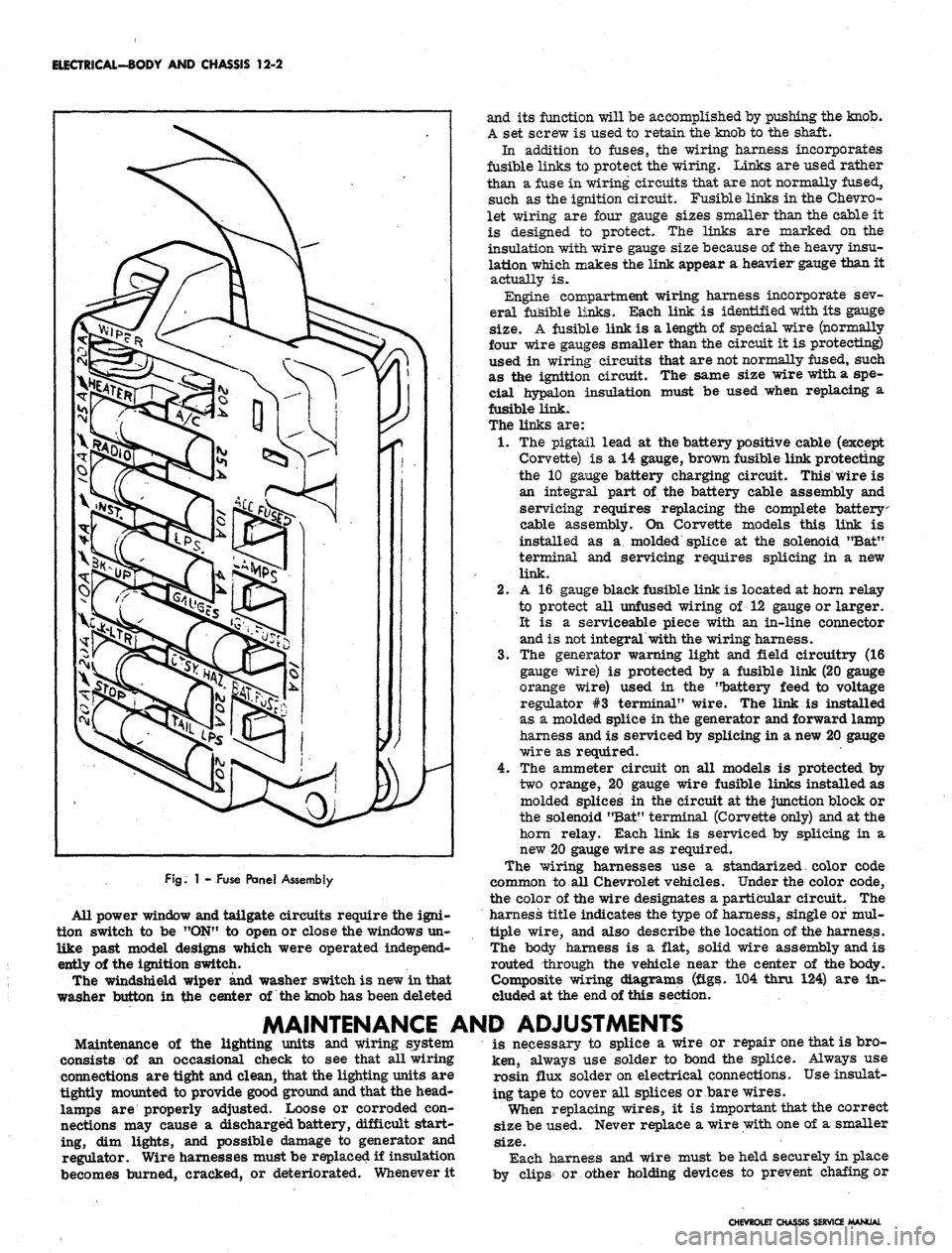
fuse panel provides convenient power take offs and fuse
clips for the appropriate circuits (fig. 1).
Chevrolet and Chevelle headlamp installation is all
new in that the headlamps are located in the radiator
support with adjusting screws and springs. Eliminating
the need for having separate headlamp housings. Chev-
rolet and Chevelle headlamp retainers and springs are
interchangeable.
Chevy n headlamp housings are new because of revised
front end styling and Corvette front end lighting is basi-
cally carryover.
Front fender lamps have been added as an option for
Chevrolet models and as standard equipment on Caprice
series.
Camaro models use single headlamps and the Rally
Sport model headlamps are covered by a retractable
section of the grille when lamps are not used. The sec-
tion of the grille covering the headlamps folds back when
lights are required; the headlamps are stationary. The
covering is retracted by a small electric motor mounted
to the headlamp housing. The headlamps are automat-
ically uncovered when the headlight switch is pulled "ON"
for illumination. If at any time the electrical circuit
becomes inoperative, the lamps can be uncovered manu-
ally. The ignition switch must be
"ON"
in order to close
the headlamp doors.
Parking lamp for Chevelle and Chevrolet models are
new due to revised front end sheet metal and bumper
styling. Parking lamps are located in the bumper on
Chevrolet, Chevelle and Chevy n models
Camaro parking lamps are located in the radiator
grille except for the Rally Sport models on which the
parking lamps are in the valance panel. For styling
reasons, the lens is white and an amber glass bulb is
used. All Camaro parking lamps require a separate
ground wire to assure a good ground contact because of
the plastic grille and painted contact surfaces.
The Chevrolet tail, stop, and directional lamps are in
one housing with a three section lens design on Impala
and Caprice sedans. The center lens for Impala series
is the back-up lamp. The center lens on the Caprice is
a tail lamp with the back-up lamps being located in the
rear bumper. Chevrolet station wagons have three indi-
vidual housings with three lenses, the center lamp being
the back-up. Biscayne and Bel-Air sedans have a single
housing and lens for tail, stop, and directional lamp with
a similarly constructed back-up lamp inboard and adja-
cent to it.
Chevelle tail, stop, and directional lamps are a single
lens design that follows through with the rear fender
styling. The back-up lamp is located in r.ear bumper.
Camaro models except Rally Sport have tail lamps
with integral back-up lamps mounted inboard of the rear
fenders between the trunk opening and bumper. The
Rally Sport model has dual tail lamps in the rear housing
and valance mounted back-up lamps.
Corvette, Chevy n, and Corvair tail and directional
signal lights are carryover. The Corvette has new back-
up lamps center mounted above the license plate opening.
CHEVROLET CHASSIS SERVICE
Page 514 of 659
ELECTRICAL-BODY AND CHASSIS 12-2
FJg.
1 - Fuse Panel Assembly
All power window and tailgate circuits require the igni-
tion switch to be "ON" to open or close the windows un-
like past model designs which were operated independ-
ently of the ignition switch.
The windshield wiper and washer switch is new in that
washer button in the center of the knob has been deleted
and its function will be accomplished by pushing the knob.
A set screw is used to retain the knob to the shaft.
In addition to fuses, the wiring harness incorporates
fusible links to protect the wiring. Links are used rather
than a fuse in wiring circuits that are not normally fused,
such as the ignition circuit. Fusible links in the Chevro-
let wiring are four gauge sizes smaller than the cable it
is designed to protect. The links are marked on the
insulation with wire gauge size because of the heavy insu-
lation which makes the link appear a heavier gauge than it
actually is.
Engine compartment wiring harness incorporate sev-
eral fusible links. Each link is identified with its gauge
size.
A fusible link is a length of special wire (normally
four wire gauges smaller than the circuit it is protecting)
used in wiring circuits that are not normally fused, such
as the ignition circuit. The same size wire with a spe-
cial hypalon insulation must be used when replacing a
fusible link.
The links are:
1.
The pigtail lead at the battery positive cable (except
Corvette) is a 14 gauge, brown fusible link protecting
the 10 gange battery charging circuit. This wire is
an integral part of the battery cable assembly and
servicing requires replacing the complete battery
cable assembly. On Corvette models this link is
installed as a molded splice at the solenoid "Bat"
terminal and servicing requires splicing in a new
link.
2.
A 16 gauge black fusible link is located at horn relay
to protect all unfused wiring of 12 gauge or larger.
It is a serviceable piece with an in-line connector
and is not integral with the wiring harness.
3.
The generator warning light and field circuitry (16
gauge wire) is protected by a fusible link (20 gauge
orange wire) used in the "battery feed to voltage
regulator #3 terminal" wire. The link is installed
as a molded splice in the generator and forward lamp
harness and is serviced by splicing in a new 20 gauge
wire as required.
4.
The ammeter circuit on all models is protected by
two orange, 20 gauge wire fusible links installed as
molded splices in the circuit at the junction block or
the solenoid "Bat" terminal (Corvette only) and at the
horn relay. Each link is serviced by splicing in a
new 20 gauge wire as required.
The wiring harnesses use a standarized. color code
common to all Chevrolet vehicles. Under the color code,
the color of the wire designates a particular circuit. The
harness title indicates the type of harness, single of mul-
tiple wire, and also describe the location of the harness.
The body harness is a flat, solid wire assembly and is
routed through the vehicle near the center of the body.
Composite wiring diagrams (figs. 104 thru 124) are in-
cluded at the end of this section.
MAINTENANCE AND ADJUSTMENTS
Maintenance of the lighting units and wiring system
consists of an occasional check to see that all wiring
connections are tight and clean, that the lighting units are
tightly mounted to provide good ground and that the head-
lamps are properly adjusted. Loose or corroded con-
nections may cause a discharged battery, difficult start-
ing, dim lights, and possible damage to generator and
regulator. Wire harnesses must be replaced if insulation
becomes burned, cracked, or deteriorated. Whenever it
is necessary to splice a wire or repair one that is bro-
ken, always use solder to bond the splice. Always use
rosin flux solder on electrical connections. Use insulat-
ing tape to cover all splices or bare wires.
When replacing wires, it is important that the correct
size be used. Never replace a wire with one of a smaller
size.
Each harness and wire must be held securely in place
by clips or other holding devices to prevent chafing or
CHEVROLET CHASSIS SERVICE MANUAL
Page 533 of 659
ELECTRICAL-BODY AND CHASSIS 12-21
2.
Remove ash tray, retainer attaching screws and
retainer.
3.
Remove Air Conditioning distributor
duct'
retaining
screws and duct.
4.
Remove heater and/or Air Conditioning control panel
assembly retaining screws and push panel assembly
from console.
NOTE:
If interference between control panel
and radio is encountered, loosen radio retaining
nuts.
5. Remove radio control knobs, bezels and retaining
nuts.
6. Disconnect radio wiring harness and antenna lead-in.
7. Remove radio rear brace attaching screw and re-
move ra(Jio from vehicle.
8. Remove ignition switch bezel nut using Tool J-7607
and push switch rearward.
9. Disconnect cigarette wiring connector.
10.
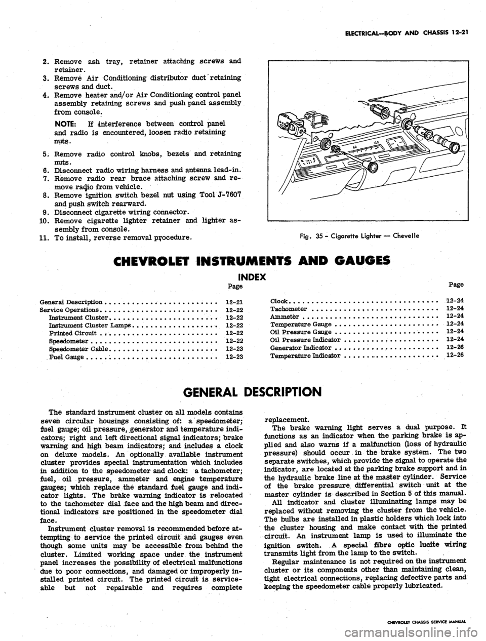
Remove cigarette lighter retainer and lighter as-
sembly from console.
11.
To install, reverse removal procedure.
Fig.
35 - Cigarette Lighter — Chevelle
CHEVROLET INSTRUMENTS AND GAUGES
INDEX
Page
General Description 12-21
Service Operations 12-22
Instrument Cluster........................ 12-22
Instrument Cluster Lamps 12-22
Printed Circuit .
* •
12-22
Speedometer 12-22
Speedometer Cable 12-23
Fuel Gauge 12-23
Page
Clock 12-24
Tachometer 12-24
Ammeter . . 12-24
Temperature Gauge 12-24
Oil Pressure Gauge 12-24
Oil Pressure Indicator 12-24
Generator Indicator 12-26
Temperature Indicator 12-26
GENERAL DESCRIPTION
The standard instrument cluster on all models contains
seven circular housings consisting of: a speedometer;
fuel gauge; oil pressure, generator and temperature indi-
cators; right and left directional signal indicators; brake
warning and high beam indicators; and includes a clock
on deluxe models. An optionally available instrument
cluster provides special instrumentation which includes
in addition to the speedometer and clock: a tachometer;
fuel, oil pressure, ammeter and engine temperature
gauges; which replace the standard fuel gauge and indi-
cator lights. The brake warning indicator is relocated
to the tachometer dial face and the high beam and direc-
tional indicators are positioned in the speedometer dial
face.
Instrument cluster removal is recommended before at-
tempting to service the printed circuit and gauges even
though some units may be accessible from behind the
cluster. Limited working space under the instrument
panel increases the possibility of electrical malfunctions
due to poor connections, and damaged or improperly in-
stalled printed circuit. The printed circuit is service-
able but not repairable and requires complete
replacement.
The brake warning light serves a dual purpose. It
functions as an indicator when the parking brake is ap-
plied and also warns if a malfunction (loss of hydraulic
pressure) should occur in the brake system. The two
separate switches, which provide the signal to operate the
indicator, are located at the parking brake support and in
the hydraulic brake line at the master cylinder. Service
of the brake pressure, differential switch unit at the
master cylinder is described in Section 5 of this manual.
All indicator and cluster illumihating lamps may be
replaced without removing the cluster from the vehicle.
The bulbs are installed in plastic holders which lock into
the cluster housing and make contact with the printed
circuit. An instrument lamp is used to illuminate the
ignition switch. A special fibre optic lucite wiring
transmits light from the lamp to the switch.
Regular maintenance is not required on the instrument
cluster or its components other than maintaining clean,
tight electrical connections, replacing defective parts and
keeping the speedometer cable properly lubricated.
CHEVROLET CHASSIS SERVICE MANUAL
Page 536 of 659
ELECTRICAL-BODY AND CHASSIS 12-24
1.
Temperature Gauge
2.
Instrument Cluster Lamp
3.
R.H. Directional Indicator
4.
Ammeter Gauge
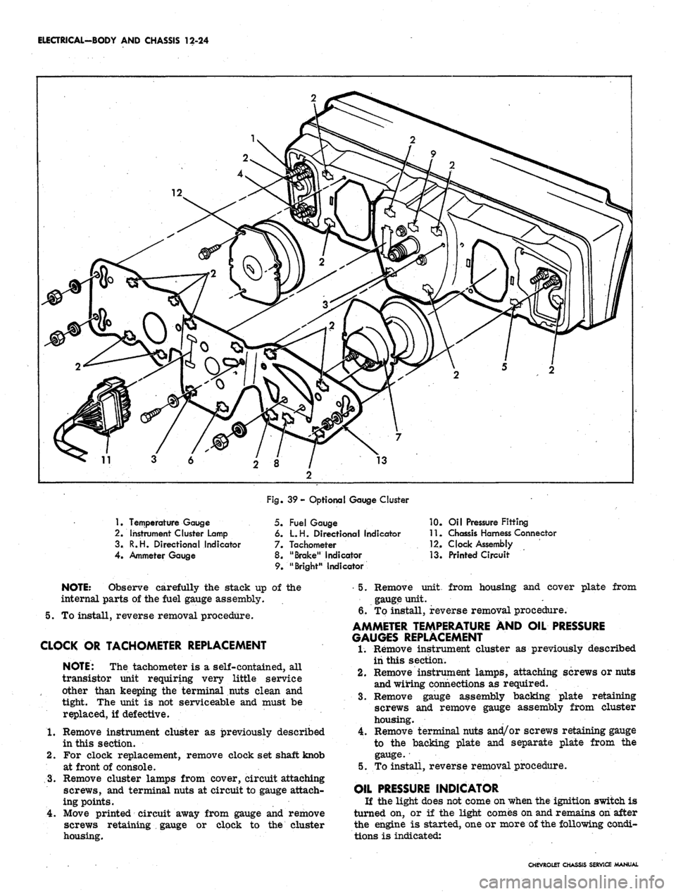
Fig. 39- Optional Gauge Cluster
5. Fuel Gauge
6. L.H. Directional Indicator
7. Tachometer
8. "Brake" Indicator
9. "Bright" Indicator
10.
Oil Pressure Fitting
11.
Chassis Harness Connector
12.
Clock Assembly
13.
Printed Circuit
NOTE:
Observe carefully the stack up of the
internal parts of the fuel gauge assembly.
5. To install, reverse removal procedure.
CLOCK OR TACHOMETER REPLACEMENT
NOTE:
The tachometer is a self-contained, all
transistor unit requiring very little service
other than keeping the terminal nuts clean and
tight. The unit is not serviceable and must be
replaced, if defective.
1.
Remove instrument cluster as previously described
in this section.
2.
For clock replacement, remove clock set shaft knob
at front of console.
3.
Remove cluster lamps from cover, circuit attaching
screws, and terminal nuts at circuit to gauge attach-
ing points.
4.
Move printed circuit away from gauge and remove
screws retaining
•_
gauge or clock to the cluster
housing.
•5.
Remove unit, from housing and cover plate from
gauge unit.
6/To install, reverse removal procedure.
AMMETER TEMPERATURE AND OIL PRESSURE
GAUGES REPLACEMENT
1.
Remove instrument cluster as previously described
iii this section.
2.
Remove instrument lamps, attaching screws or nuts
and wiring connections as required.
3.
Remove gauge assembly backing plate retaining
screws and remove gauge assembly from cluster
housing.
4.
Remove terminal nuts and/or screws retaining gauge
to the backing plate and separate plate from the
gauge.
•
5. To install, reverse removal procedure.
OIL PRESSURE INDICATOR
If the light does not come on when the ignition switch is
turned on, or if the light comes on and remains on after
the engine is started, one or more of the following condi-
tions is indicated:
CHEVROLET CHASSIS SERVICE MANUAL