ESP CHEVROLET CAMARO 1967 1.G Chassis Workshop Manual
[x] Cancel search | Manufacturer: CHEVROLET, Model Year: 1967, Model line: CAMARO, Model: CHEVROLET CAMARO 1967 1.GPages: 659, PDF Size: 114.24 MB
Page 17 of 659
LUBRICATION 0-15
CRANKCASE VENTILATION VALVE
VALVE TYPE
NOTE: Under prolonged dusty driving condi-
tions,
it is recommended that these operations
be performed more often. Every 12,000 miles
or 12 months the valve should be replaced.
Connecting hoses, fittings, flame arrestor and
crankcase breather cap (where used) should be
cleaned. At every oil change the system should
be tested for proper function and serviced, if
necessary.
FUEL FILTER
Replace filter element located in carburetor inlet if
flooding occurs, if engine surges during constant speed
operation (pulsating effect) or if poor performance is
experienced during acceleration or at higher speeds.
AIR CLEANER
NOTE: Under prolonged dusty driving condi-
tions,
it is recommended that these operations
be performed more often.
POLYURETHANE TYPE-
Every 12,000 miles clean element in solvent, squeeze
out solvent, then soak in engine oil and squeeze out
excess.
OIL WETTED PAPER ELEMENT TYPE-
First 12,000 miles inspect or test element; if satis-
factory, re-use element but recheck every 6,000 miles
until replaced. Element must not be washed, oiled,
tapped or cleaned with an air hose.
BATTERY TERMINAL WASHERS
Battery terminals have felt washers between top of
case and cable connections to minimize corrosive action
of battery acid. These felt washers should be saturated
with engine oil every 6,000 miles.
DISTRIBUTOR
4 and 6-Cylinder Engine—Remove distributor cap and
rotate lubricator 1/2 turn at 12,000 mile intervals. Re-
place at 24,000 mile intervals.
8-Cylinder Engine—Change cam lubricator end for end
at 12,000 mile intervals. Replace at 24,000 mile
intervals.
REAR AXLE AND 3-SPEED AND
OVERDRIVE, 4-SPEED TRANSMISSIONS
The passenger car operates under the most severe
lubrication conditions at high speed and requires a hypoid
lubricant which will meet this condition.
Recommended Lubricants
Standard Rear Axles—SAE 90 "Multi-Purpose" gear
lubricant.
Positraction Rear Axles—Use special Positraction
lubricant.
CAUTION: Straight Mineral Oil gear lubricants
must not be used in hypoid rear axles.
Transmissions—SAE 90 "Multi-Purpose" gear
lubricant.
The SAE 90 viscosity grade is recommended for year
round use. However, when extremely low temperatures
are encountered for protracted periods during the winter
months, the SAE 80 viscosity grade may be used.
"Multi-Purpose" Gear Lubricants
Gear lubricants that will satisfactorily lubricate hypoid
rear axles have been developed and are commonly re-
ferred to as ' 'Multi-Purpose" gear lubricants meeting
U.S.
Army Ord. Spec. MIL-L-2105B.
These lubricants can also be satisfactorily used in
manual transmissions.
CAUTION: With Positraction rear axles use
special Positraction lubricant.
"Multi-Purpose" gear lubricants must be manufac-
tured under carefully controlled conditions and the
lubricant manufacturer must be responsible for the
satisfactory performance of his product. His reputation
is the best indication of quality.
Lubricant Additions
The lubricant level in the axle and transmission hous-
ings should be checked periodically. (Every 6,000 miles.)
It is recommended that any additions required to bring
up the lubricant level be made using the same type lubri-
cant already in the housing.
When checking lubricant level in transmission or rear
axle the unit being cheeked should be at operating
temperature. With unit at operating temperature the
lubricant should be level with bottom of the filler plug
hole.
If the lubricant level is checked with the unit cold
the lubricant level should be 1/2 inch below the filler
plug hole.
Lubricant Changes
The rear axle lubricant does not require changing for
the life of the vehicle. If additions are needed, or when
refilling the axle after service procedures, use lubricants
described above.
POWERGLIDE TRANSMISSION
NOTE: Every 12,000 miles, it is recommended
that the Powerglide low band be adjusted as
specified in Section 7 of this manual.
Every 6,000 miles--Check fluid level on dipstick with
engine idling, selector lever in neutral position, parking
brake set and transmission at operating temperature. If
fluid level is below full mark on dip stick, adding a small
amount of Automatic Transmission Fluid, General Motors
Automatic Transmission Fluid (Part Numbers 1050568-
69,
70) is recommended. If this fluid is not obtainable,
use Automatic Transmission Fluid Type 'A' bearing the
mark AQ-ATF followed by a number and the suffix letter
'A'.
Recheck fluid level on dip stick and again add a
small amount of fluid if needed to bring level to full
mark. DO NOT OVERFILL.
CHEVROLET CHASSIS SERVICE MANUAL
Page 45 of 659
HEATER AND AIR CONDITIONING 1A-22
RECEIVER &
OEHYDRATOR ASM
HOSES
CONDENSER
ASM.
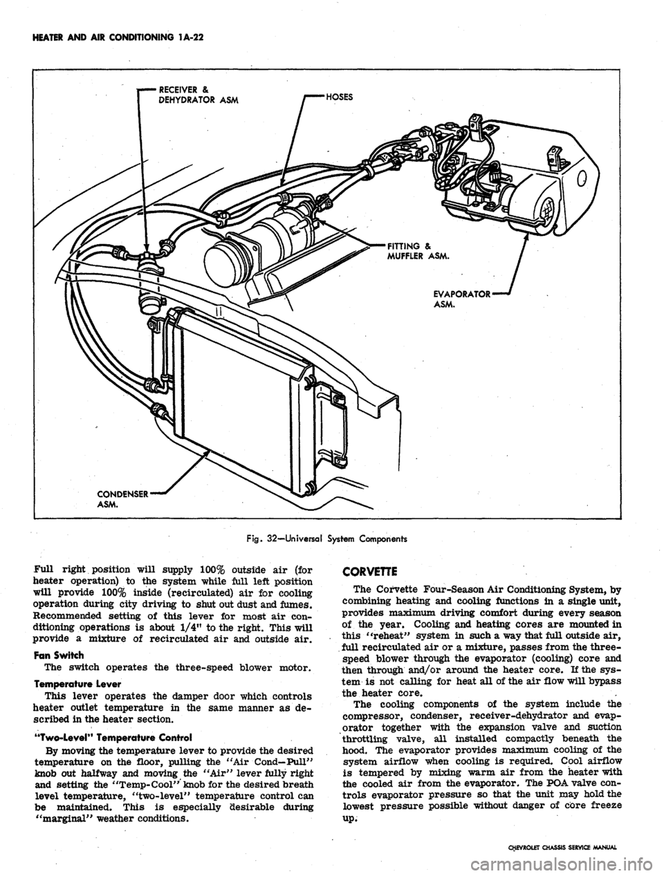
Fig.
32—Universal System Components
Full right position will supply 100% outside air (for
heater operation) to the system while full left position
will provide 100% inside (recirculated) air for cooling
operation during city driving to shut out dust and fumes.
Recommended setting of this lever for most air con-
ditioning operations is about 1/4" to the right. This will
provide a mixture of recirculated air and outside air.
Fan Switch
The switch operates the three-speed blower motor.
Temperature Lever
This lever operates the damper door which controls
heater outlet temperature in the same manner as de-
scribed in the heater section.
"Two-Level"
Temperature Control
By moving the temperature lever to provide the desired
temperature on the floor, pulling the "Air Cond— Pull"
knob out halfway and moving the "Air" lever fully right
and setting the "Temp-Cool" knob for the desired breath
level temperature, "two-level" temperature control can
be maintained. This is especially desirable during
"marginal" weather conditions.
CORVETTE
The Corvette Four-Season Air Conditioning System, by
combining heating and cooling functions in a single unit,
provides maximum driving comfort during every season
of the year. Cooling and heating cores are mounted in
this "reheat" system in such a way that full outside air,
full recirculated air or a mixture, passes from the three-
speed blower through the evaporator (cooling) core and
then through and/or around the heater core. If the sys-
tem is not calling for heat all of the air flow will bypass
the heater core.
The cooling components of the system include the
compressor, condenser, receiver-d,ehydrator and evap-
orator together with the expansion valve and suction
throttling valve, all installed compactly beneath the
hood. The evaporator provides maximum cooling of the
system airflow when cooling is required. Cool airflow
is tempered by mixing warm air from the heater with
the cooled air from the evaporator. The PDA valve con-
trols evaporator pressure so that the unit may hold the
lowest pressure possible without danger of core freeze
up.
CHEVROLET CHASSIS SERVICE MANUAL
Page 49 of 659
HEATER AND AIR CONDITIONING 1A-26
clockwise for medium and high blower speed, as
desired. Low blower speed is automatic during
cooling operations.
4.
"Def-Pull". This knob should be pushed fully in.
Additional Cooling Hints
1.
The center barrel outlet in the dash may be rotated
to deflect air as desired or used to act as a shut off
door.
2.
The right and left ball outlets may be rotated to
deflect air in the direction desired. Each outlet has
a shut off valve operated by a knob approximately
4 in. inboard. When the knob is horizontal, the valve
is open.
3.
There are two (2) additional outlets in the bottom of
the ducts approximately 6" inboard from the valve
knobs. A rotating cover will open these outlets to
provide cool air for the feet if desired.
4.
When first entering a very warm car, open the
windows for a few minutes until the interior of the
car has cooled off.
Heating
1.
"Air Pull-Fan". Pull this knob fully out. Rotate
the knob clockwise for low, medium or high blower
speed as desired. If just a small amount of heat is
desired, leave the fan on low or medium speed and
regulate the temperature with the "Cool In-Hot Pull"
knob.
2.
"Air Cond-Pull". This knob should normally be
pushed fully in. However, during cool, damp days
it is possible, by pulling this knob fully out, to de-
humidify the air by passing it through the evaporator
core before reheating to the desired outlet
temperature.
3.
"Cool In-Hot Pull". Pull this knob out as far as
necessary to provide the temperature desired.
4.
"Def-Pull". Pull this knob all the way out for
maximum defrosting or de-icing. When the knob is
partly out, a portion of the hot air is used for de-
frosting and the balance is discharged through the
heater outlet.
GENERAL INFORMATION
In any vocation or trade, there are established proce-
dures and practices that have been developed after many
years of experience. In addition, occupational hazards
may be present that require the observation of certain
precautions or use of special tools and equipment. Ob-
serving the procedures, practices and precautions of
servicing refrigeration equipment will greatly reduce the
possibilities of damage to the customers' equipment as
well as virtually eliminate the element of hazard to the
serviceman.
PRECAUTIONS IN HANDLING REFRIGERANT-12
Refrigerant-12 is transparent and colorless in both the
gaseous and liquid state. It has a boiling point of 21.7^
below zero and, therefore, at all normal temperatures
and pressures it will be a vapor. The vapor is heavier
than air and is noninflammable, nonexplosive, non-
poisonous (except when in contact with an open flame)
and noncorrosive (except when in contact with water).
The following precautions in handling R-12 should be
observed at all times.
• All refrigerant drums are shipped with a heavy metal
screw cap. The purpose of the cap is to protect the
valve and safety plug from damage. It is good .prac-
tice to replace the cap after each use of the drum.
• If it is ever necessary to transport or carry a drum
or can of refrigerant in a car, keep it in the luggage
compartment. Refrigerant should not be exposed to
the radiant heat from the sun for the resulting in-
crease in pressure may cause the safety plug to
release or the drum or can to burst..
• Drums or disposable cans should never be subjected
to high temperature when adding refrigerant to the
system. In most instances, heating the drum or can
is required to raise the pressure in the container
higher than the pressure in the system during the
operation. It would be unwise to place the drum on a
gas stove, radiator or use a blow torch while pre-
paring for the charging operation, for a serious ac-
cident can result. Don't depend on the safety
plug - many drums have burst when the safety plug
failed.' Remember, high pressure means that great
forces are being exerted against the walls of the
container. A bucket of warm water, not over 125°F,
or warm wet rags around the container is all the heat
that is required.
• Do not weld or steam clean on or near the system.
Welding or steam cleaning can result in a dangerous
pressure buildup in the system.
• When filling a small drum from a large one, never
fill the drum completely. Space should always be
allowed above the liquid for expansion. If the drum
were completely full and the temperature was in-
creased, hydraulic pressure with its tremendous
force would result.
• Discharging large quantities of R-12 into a room can
usually be done safely as the vapor would produce
no ill effects, however, in the event of an accidental
rapid discharge of the system it is recommended
that inhalation of large quantities of R-12 be avoided.
This caution is especially important if the area con-
tains a flame producing device such as a gas heater.
While R-12 normally is nonpoisonous, heavy con-
centrations.. of it in contact with a live flame will
produce a toxic gas. The same gas will also attack
all bright metal surfaces.
• Protection of the eyes is of vital importance! When
working around a refrigerating system, an accident
may cause liquid refrigerant to hit the face. If the
eyes are protected with goggles or glasses, no
serious damage can result. Just remember, any
R-12 liquid that you can touch or that touches you is
at least 21.7"F. below zero. The eyeballs can't take
much of this temperature. If R-12 liquid should
strike the eyeballs, here is what to do:
1.
Keep calm.
2.
Do not rub the eyes! Splash the affected area with
quantities of cold water to gradually get the tem-
perature above the freezing point. The use of min-
eral, cod liver or an antiseptic oil is important in
CHEVROLET CHASSIS SERVICE MANUAL
Page 54 of 659
HEATER
AND AIR
CONDITIONING
1A-31
FIVE
AMP
TIME DELAY
FUSE
CORD
TO
110
AC
SOURCE
PUMP
INLET
PUMP DISCHARGE
OUTLET
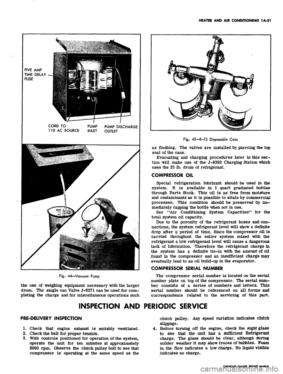
Fig.
44—Vacuum Pump
the use of weighing equipment necessary with the larger
drum. The single can Valve J-6271 can be used for com-
pleting the charge and for miscellaneous operations such
Fig.
45-R-12 Disposable Cans
as flushing. The valves are installed by piercing the top
seal of the cans.
Evacuating and charging procedures later in this sec-
tion will make use of the J-8393 Charging Station which
uses the 25 lb. drum of refrigerant.
COMPRESSOR OIL
Special refrigeration lubricant should be used in the
system. It is available in 1 quart graduated bottles
through Parts Stock. This oil is as free from moisture
and contaminants as it is possible to attain by commercial
processes. This condition should be preserved by im-
mediately capping the bottle when not in use.
See "Air Conditioning System Capacities" for the
total system oil capacity.
Due to the porosity of the refrigerant hoses and con-
nections, the system refrigerant level will show a definite
drop after a period of time. Since the compressor oil is
carried throughout the entire system mixed with the
refrigerant a low refrigerant level will cause a dangerous
lack of lubrication. Therefore the refrigerant charge in
the system has a definite tie-in with the amount of oil
found in the compressor and an insufficient charge may
eventually lead to an oil build-up in the evaporator.
COMPRESSOR SERIAL NUMBER
The compressor serial number is located on the serial
number plate on top of the compressor. The serial num-
ber consists of a series of numbers and letters. This
serial number should be referenced on all forms and
correspondence related to the servicing of this part.
INSPECTION AND PERIODIC SERVICE
PRE-DELIVERY INSPECTION
1.
Check that engine exhaust is suitably ventilated.
2.
Check the belt for proper tension.
3.
With controls positioned for operation of the system,
operate the unit for ten minutes at approximately
2000 rpm. Observe the clutch pulley bolt to see that
compressor is operating at the same speed as the
clutch pulley. Any speed variation indicates clutch
slippage.
Before turning off the engine, check the sight glass
to see that the.unit has a sufficient Refrigerant
charge. The glass should be clear, although during
milder weather it may show traces of bubbles. Foam
in.
the flow indicates a low charge. No liquid visible
indicates no charge.
CHEVROLET CHASSIS SERVICE MANUAL
Page 91 of 659
HEATER AND AIR CONDITIONING 1A-68
Fig.
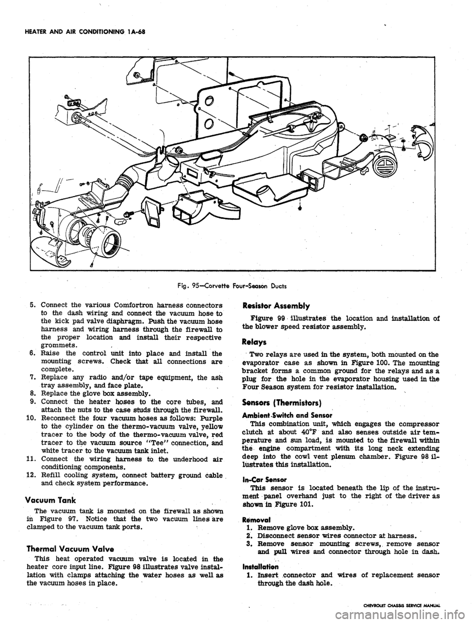
95—Corvette Four-Season Ducts
5. Connect the various Comfortron harness connectors
to the dash wiring and connect the vacuum hose to
the kick pad valve diaphragm. Push the vacuum hose
harness and wiring harness through the firewall to
the proper location and install their respective
grommets.
6. Raise the control unit into place and install the
mounting screws. Check that all connections are
complete.
7. Replace any radio and/or tape equipment, the ash
tray assembly, and face plate.
8. Replace the glove box assembly.
9. Connect the heater hoses to the core tubes, and
attach the nuts to the case studs through the firewall.
10.
Reconnect the four vacuum hoses as follows: Purple
to the cylinder on the thermo-vacuum valve, yellow
tracer to the body of the thermo-vacuum valve, red
tracer to the vacuum source "Tee" connection, and
white tracer to the vacuum tank inlet.
11.
Connect the wiring harness to the underhood air
conditioning components.
12.
Refill cooling system, connect battery ground cable
and check system performance.
Vacuum Tank
The vacuum tank is mounted on the firewall as shown
in Figure 97. Notice that the two vacuum lines are
clamped to the vacuum tank ports. *
Thermal Vacuum Valve
This heat operated vacuum valve is located in the
heater core input line. Figure 98 illustrates valve instal-
lation with clamps attaching the water hoses as well as
the vacuum hoses in place.
Resistor Assembly
Figure 99 illustrates the location and installation of
the blower speed resistor assembly.
Relays
Two relays are used in the system, both mounted on the
evaporator case as shown in Figure 100. The mounting
bracket forms a common ground for the relays and as a
plug for the hole in the evaporator housing used in the
Four Season system for resistor installation.
Sensors (Thermistors)
Ambient Switch and Sensor
This combination unit, which engages the compressor
clutch at about 40°F and also senses outside air tem-
perature and sun load, is mounted to the firewall within
the engine compartment with its long neck extending
deep into the cowl vent plenum chamber. Figure 98 il-
lustrates this installation,
In-Car Sensor
This sensor is located beneath the lip of the instru-
ment panel overhand just to the right of the driver as
shown in Figure 101.
Removal
1.
Remove glove box assembly.
2.
Disconnect sensor wires connector at harness.
3.
Remove sensor mounting screws, remove sensor
and pull wires and connector through hole in dash.
Installation
1.
Insert connector and
through the dash hole.
wires of replacement sensor
CHEVROLET CHASSIS SERVICE MANUAL
Page 136 of 659
CORVETTE BODY 1B-29
CUSHION
CUSHION ASNi.^ty** ACCESS
#2 BODY BRACKET
( 67 ONLY)
SHIM
( 37 POSITION).
CUSHION ASM.
( 37)
SHIM
( 67 POSITION)
CUSHION
( 37 ONLY)
#1 BODY BRACKET
Fig.
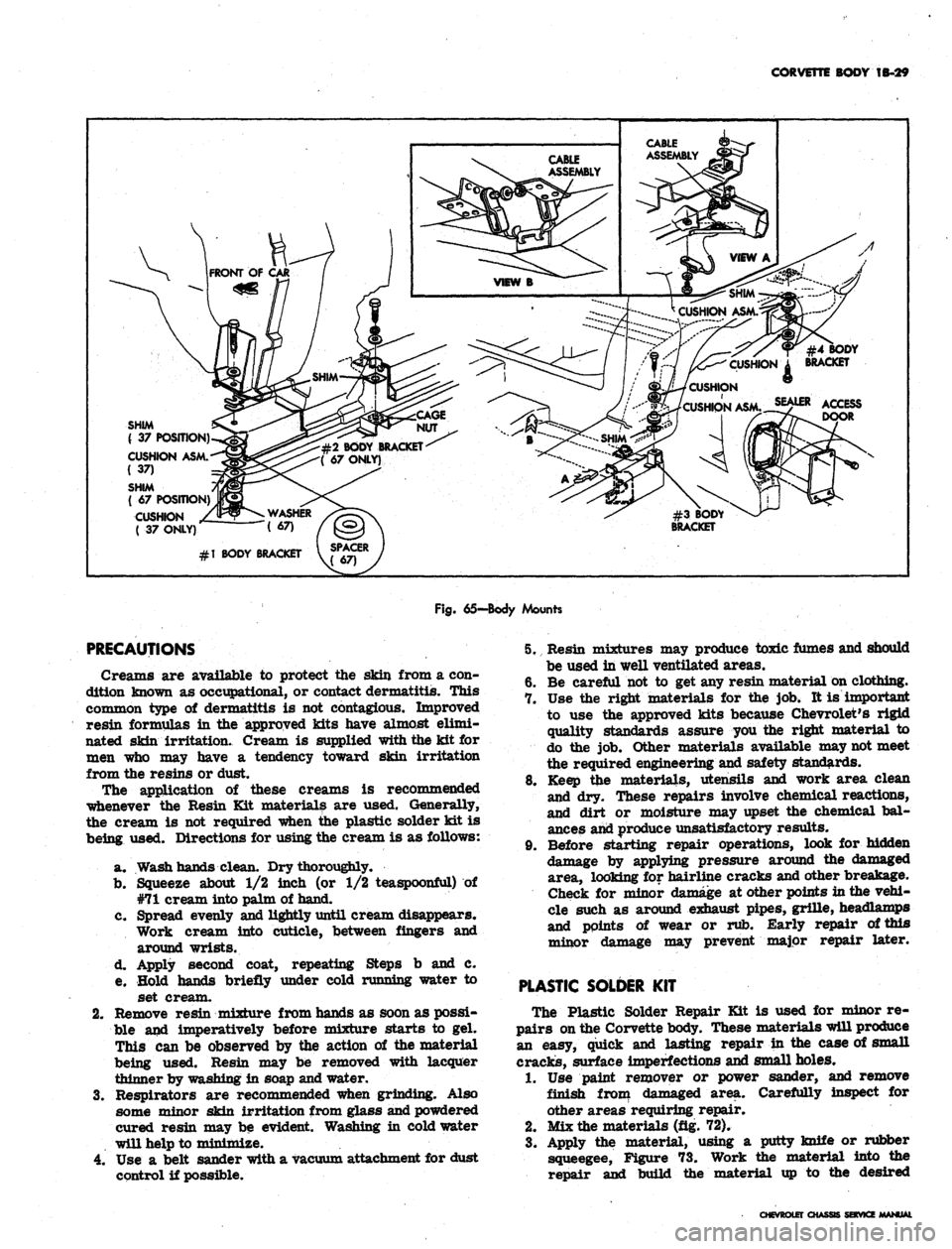
65—Body Mounts
PRECAUTIONS
Creams are available to protect the skin from a con-
dition known as occupational, or contact dermatitis. This
common type of dermatitis is not contagious. Improved
resin formulas in the approved kits have almost elimi-
nated skin irritation. Cream is supplied with the kit for
men who may have a tendency toward skin irritation
from the resins or dust.
The application of these creams is recommended
whenever the Resin Kit materials are used. Generally,
the cream is not required when the plastic solder kit is
being used. Directions for using the cream is as follows:
a. Wash hands clean. Dry thoroughly.
b.
Squeeze about 1/2 inch (or 1/2 teaspoonful) of
#71 cream into palm of hand.
c. Spread evenly and lightly until cream disappears.
Work cream into cuticle, between fingers and
around wrists.
d. Apply second coat, repeating Steps b and c.
e. Hold hands briefly under cold running water to
set cream.
2.
Remove resin mixture from hands as soon as possi-
ble and imperatively before mixture starts to gel.
This can be observed by the action of the material
being used. Resin may be removed with lacquer
thinner by washing in soap and water.
3.
Respirators are recommended when grinding. Also
some minor skin irritation from glass and powdered
cured resin may be evident. Washing in cold water
will help to minimize.
4.
Use a belt sander with a vacuum attachment for dust
control if possible.
5. Resin mixtures may produce toxic fumes and should
be used in well ventilated areas.
6. Be careful not to get any resin material on clothing.
7. Use the right materials for the job. It is important
to use the approved kits because Chevrolet's rigid
quality standards assure you the right material to
do the job. Other materials available may not meet
the required engineering and safety standards.
8. Keep the materials, utensils and work area clean
and dry. These repairs involve chemical reactions,
and dirt or moisture may upset the chemical bal-
ances and produce unsatisfactory results.
9. Before starting repair operations, look for hidden
damage by applying pressure around the damaged
area, looking for hairline cracks and other breakage.
Check for minor damage at other points in the vehi-
cle such as around exhaust pipes, grille, headlamps
and points of wear or rub. Early repair of this
minor damage may prevent major repair later.
PLASTIC SOLDER
KIT
The Plastic Solder Repair Kit is used for minor re-
pairs on the Corvette body. These materials will produce
an easy, quick and lasting repair in the case of small
cracks, surface imperfections and small holes.
1.
Use paint remover or power sander, and remove
finish from damaged area. Carefully inspect for
other areas requiring repair.
2.
Mix the materials (fig. 72).
3.
Apply the material, using a putty knife or rubber
squeegee, Figure 73. Work the material into the
repair and build the material up to the desired
CHEVROLET CHASSIS SERVICE
Page 159 of 659
CORVETTE BODY 1B-52
and pull weatherstrip and trim from rear bow.
Section A-A shows installed position of these com-
ponents. Refer also to figure 105.
installation
1.
Find and mark center of header, #3 bow, rear bow
and leading and trailing edges of top trim. Align
these marks during installation and recheck their
alignment from time to time while installation is in
progress, especially during tacking or stapling.
2.
Assemble top trim and weatherstrip to rear bow,
referring to Section A-A and Figure 105. Note that
filler strip locks this assembly together and goes
in last. Align center marks.
3.
If new pads are required, install at this time, align-
ing with marks made when old pads were removed.
Figure 106 shows pad construction; Figure 107 shows
pad installed.
4.
Install top trim-rear bow assembly on top frame
with four screws removed at disassembly.
5.
Lock down rear bow in desired "top up" position.
Pull up stay straps and staple or tack to #3 bow
(fig. 108).
6. Pull leading edge of trim iip to header and align
center marks. Smooth out fabric and clamp, tack
or staple temporarily to header.
7.
Draw window extension up to #3 bow, aligning cen-
tering marks. Turn an ample amount of fabric under
and tack to #3 bow. Apply neoprene trim cement,
GM Part #3695016 or equivalent, to area shown in
View D of Figure 102. Follow directions on package.
8. Draw roof portion of trim over #3 bow, align marks
and tack on staple.
9. Trim off excess material and install wire-on binding
as shown in Figure 109 and View D of Figure 102.
Install binding caps.
10.
Remove temporary clamps or fastenings holding trim
to header.
11.
With header locked down, pull trim assembly up tight
and mark for final installation.
12.
Apply trim cement to header and rear side rail.
13.
Release header from windshield. Tack or staple trim
to header (fig. 103).
14.
Apply trim to rear side frame, previously cemented.
15.
Install weatherstrips which were removed at dis-
assembly and install retaining screws in header
weatherstrip.
16.
Make any adjustments necessary, following instruc-
tions listed under Folding Top—Adjustments.
FRAME AND LINKAGE
Figure 110 illustrates construction features of the
folding top frame and linkage. Various cross sections in
Figure 110 show the pivoting joints and their assembly.
If an operation is being performed which requires
removal of folding top trim, follow directions in this
section. The entire frame assembly may be removed and
replaced as a unit. Follow instructions for Folding Top
Trim and Rear Window Assembly and Top Assembly—
Removal and Installation.
The pivoting joints should be lubricated with light
machine oil once a year. Apply oil sparingly so as not
to stain top trim.
WEATHERSTRIP
Side Rail Weatherstrip
Figure 111 illustrates installation of side rail weather-
strip which acts to seal window opening. The weather-
strip is held in place by studs which are part of the
weatherstrip assembly, and by neoprene base cement
which is applied between weatherstrip and side rail
surface.
When replacing weatherstrip remove all rust, old
cement and foreign material from the surfaces to be
cemented, to assure successful bonding. Use only good
quality neoprene cement suitable for weatherstrip
application.
Header Weatherstrip
Weatherstrip assembly is retained to the header panel
by a combination of studs, sheet metal screws and special
fasteners as shown in Figure 112, along with neoprene
base weatherstrip cement.
Figure 99 shows' a cross section of weatherstrip taken
through a special fastener. To replace fastener, rotate
ninety degrees to align fastener head with slot. Follow
directions for cementing in the Side Rail Weatherstrip
instructions preceding this write up.
ADDING HARDTOP (ROOF PANEL ASSEMBLY)
An available roof panel assembly (hardtop) complete
can be added to convertible model Corvettes. The hard-
ware is included with the panel assembly.
Reworking of a plastic part (one for each side of the
roof panel) can be used as a marker for drilling of two
required holes in the folding top compartment lid* Hard-
ware is attached at four locations — two on the lid and
two (one each side) at the lock pillar area as follows:
1.
Rework two plastic retainers (#6280765) (used on
Chevrolet and Corvair door inner panels for trim
retention) as shown by Figure 113.
2.
Slide the reworked plastic retainers into the bolt re-
tainer slots on each side of the hardtop rear bow
(position plastic tip inboard).
3.
Mark the hardtop reveal molding at the approximate
location of the two plastic retainers,
4.
Mark the tips of the two plastic retainers with a
china marker pencil.
5.
Close the soft top compartment lid.
6. With aid of an ^assistant, position front of hardtop
onto header and lower onto vehicle. Do not fasten
latches at windshield header.
7.
Apply hand pressure at reveal molding marks.
8. Mark roof panel attachment hole location at each
lock pillar area (fig. 114).
9. With aid of an assistant, lift roof panel straight up
off body and set roof panel aside.
10.
Mark the drill position at the four china marks with
a center punch.
11.
Place a 2" x 4" board under the top compartment lid
to prevent drill damage to folding top material. Make
certain the compartment lid is securely locked
before drilling.
12.
Drill 1/8" pilot hole at the 4 marked locations.
CHEVROLET CHASSIS SERVICE MANUAL
Page 205 of 659
REAR SUSPENSION AND DRIVE LINE 4-15
ship of parts, then install Spacer J-
7574-
3 over
the partially installed bushing and between the
sides of the control arm.
f. Continue to tighten J-
21058-
8
until bushing is
pulled flush against control arm. Do not exert
undue force against control arm after bushing is
installed. Overtightening of J-21058-
8
will cause
damage to walls of control arm.
g. Disassemble tools and inspect bushing for proper
installation.
Replace the rear bushing as follows:
a. Position Puller Screw J-21058-8 through Re-
mover Adapter J-21830-2 so that head of screw
is opposite button end of remover. Install this
assembly, threaded end of sc'rew first, through
bushing to be removed.
b.
Install Receiver J-21830-4 and Bridge J-21830-7
. over screw and against control arm. Position
thrust bearing against J-21830-7 and screw
J-21058-8 snugly against bearing. Install Spacer
J-
2183d-
3
between sides of control arm and over
bushing.
c. Check tool installation for proper alignment and
tighten J-21058-8 to withdraw bushing from con-
trol arm. Refer to Figure 35 for installed view
of tools.
d. Disassemble tools and position Installer Adapter
J-21830-2 on flanged end of new bushing. Posi-
tion bushing in control arm making sure of cor-
rect installation. Small end of bushing will pass
through one side of arm without any interference.
e. Install J-21830-4, J-21830-7, thrust bearing and
J-21058-8 on threaded end of J-21058-15 as
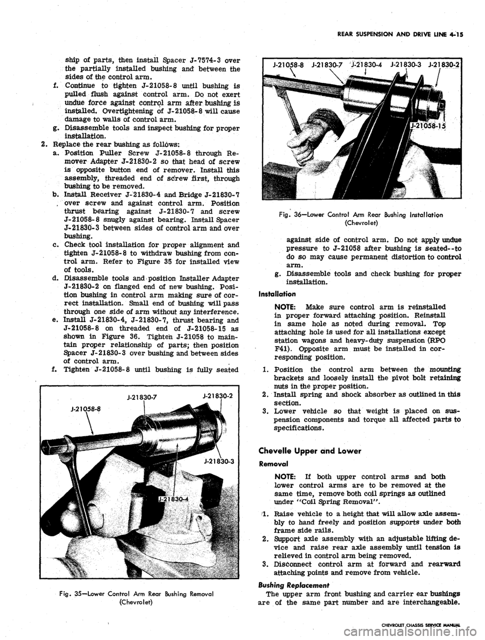
shown in Figure 36. Tighten J-21058 to main-
tain proper relationship of parts; then position
Spacer J- 21830- 3 over bushing and between sides
of control arm.
f. Tighten J-21058-8 until bushing is fully seated
J-21058-8 J-21830-7 J-21830-4 J-21830-3 J-21830-2
\
J-2K
X
D58-8
J-218
30-7
IP
•he?
21830-4
J-21830-2
JfSir
J-21830-3
Fig.
35—Lower Control Arm Rear Bushing Removal
(Chevrolet)
Fig.
36—Lower Control Arm Rear Bushing Installation
(Chevrolet)
against side of control arm. Do not apply undue
pressure to J-21058 after bushing is seated--to
do so may cause permanent distortion to control
arm.
g. Disassemble tools and check bushing for proper
installation.
Installation
NOTE:
Make sure control arm is reinstalled
in proper forward attaching position. Reinstall
in same hole as noted during removal. Top
attaching hole is used for all installations except
station wagons and heavy-duty suspension (RPO
F41).
Opposite arm must be installed in cor-
responding position.
1.
Position the control arm between the mounting
brackets and loosely install the pivot bolt retaining
nuts in the proper position.
2.
Install spring and shock absorber as outlined in this
section.
3.
Lower vehicle so that weight is placed on sus-
pension components and torque all affected parts to
specifications.
Chevelle Upper and Lower
Removal
NOTE:
If both upper control arms and both
lower control arms are to be removed at the
same time, remove both coil springs as outlined
under "Coil Spring Removal".
1.
Raise vehicle to a height that will allow axle assem-
bly to hand freely and position supports under both
frame side rails.
2.
Support axle assembly with an adjustable lifting de-
vice and raise rear axle assembly until tension is
relieved in control arm being removed.
3.
Disconnect control arm at forward and rearward
attaching points and remove from vehicle.
Bushing Replacement
The upper arm front bushing and carrier ear bushings
are of the same part number and are interchangeable.
CHEVROLET CHASSIS SERVICE MANUAL
Page 211 of 659
REAR SUSPENSION AND DRIVE LINE 4-21
Fig.
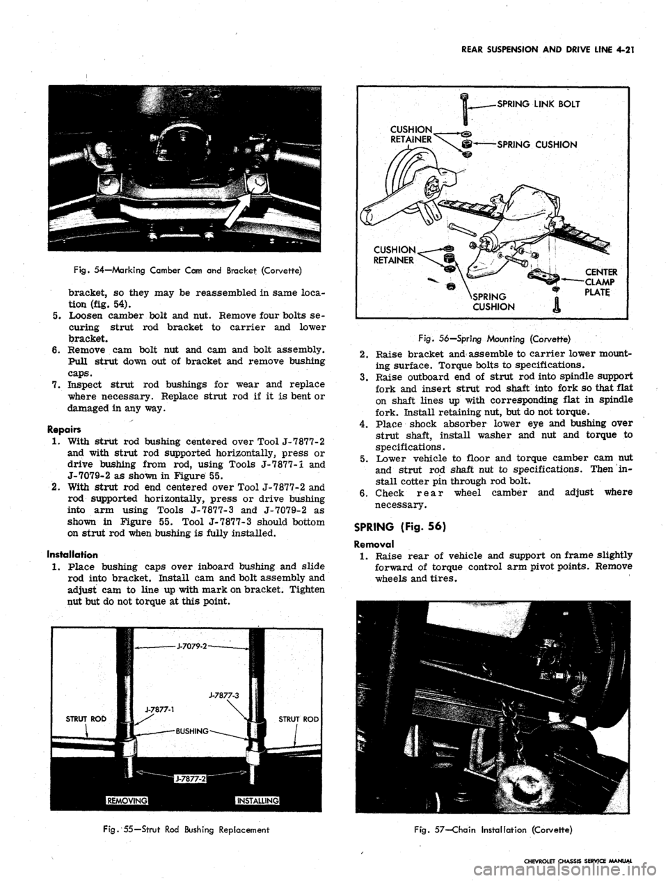
54—Marking Camber Cam and Bracket (Corvette)
bracket, so they may be reassembled in same loca-
tion (fig. 54).
5.
Loosen camber bolt and nut. Remove four bolts se-
curing strut rod bracket to carrier and lower
bracket.
6. Remove cam bolt nut and cam and bolt assembly.
Pull strut down out of bracket and remove bushing
caps.
7.
Inspect strut rod bushings for wear and replace
where necessary. Replace strut rod if it is bent or
damaged in any way.
Repairs
1.
With strut rod bushing centered over Tool J-7877-2
and with strut rod supported horizontally, press or
drive bushing from rod, using Tools J-7877-i and
J-7079-2 as shown in Figure 55.
2.
With strut rod end centered over Tool J-7877-2 and
rod supported horizontally, press or drive bushing
into arm using Tools J-7877-3 and J-7079-2 as
shown in Figure 55. Tool J-7877-3 should bottom
on strut rod when bushing is fully installed.
Installation
1.
Place bushing caps over inboard bushing and slide
rod into bracket. Install cam and bolt assembly and
adjust cam to line up with mark on bracket. Tighten
nut but do not torque at this point.
SPRING
LINK BOLT
SPRING
CUSHION
SPRING
CUSHION
CENTER
CLAMP
PLATE
J-7877-3
J-7877-1
STRUT ROD 11 s* ^#3 STRUT ROD
BUSHING
Fig.
56—Spring Mounting (Corvette)
2.
Raise bracket and assemble to carrier lower mount-
ing surface. Torque bolts to specifications.
3.
Raise outboard end of strut rod into spindle support
fork and insert strut rod shaft into fork so that flat
on shaft lines up with corresponding flat in spindle
fork. Install retaining nut, but do not torque.
4.
Place shock absorber lower eye and bushing over
strut shaft, install washer and nut and torque to
specifications.
5.
Lower vehicle to floor and torque camber cam nut
and strut rod shaft nut to specifications. Then in-
stall cotter pin through rod bolt.
6. Check rear wheel camber and adjust where
necessary.
SPRING (Fig. 56)
Removal
1.
Raise rear of vehicle and support on frame slightly
forward of torque control arm pivot points. Remove
wheels and tires.
Fig.
55—Strut Rod Bushing Replacement
Fig.
57—Chain Installation (Corvette)
CHEVROLET CHASSIS SERVICE MANUAL
Page 264 of 659
BRAKES
5-31
POWER BRAKES
INDEX
General Description 5-31
Maintenance
and"
Adjustments 5-31
Inspection . ... 5_31
Lubrication 5-31
Bleeding Instructions . . . 5.31
Air Cleaner Service . . . , 5.31
Page
Component Replacement 5-31
Power Brake Cylinder ......* 5-31
Removal . . 5-31
Disassembly and Assembly See Overhaul Manual
Installation . . . . 5-31
GENERAL DESCRIPTION
The Power Brake Unit is a self-contained hydraulic
and vacuum unit, utilizing manifold vacuum and atmos-
phere pressure for its power.
This unit permits the use of a low brake pedal as well
as less pedal effort than is required with the conventional
(nonpower) hydraulic brake system. Only two external
line connections are necessary -
one
a vacuum connection
from manifold to check valve located on front shell; the
other, a hydraulic connection from the main cylinder
outlet directly into the hydraulic system. The unit is
mounted on the engine side of the fire wall and directly
connected to the brake pedal.
MAINTENANCE AND ADJUSTMENTS
INSPECTIONS
1.
Check vacuum line and vacuum line connections as
well as vacuum check valve in front shell of power
unit for possible vacuum loss.
2.
Inspect all hydraulic lines and connections at the
wheel cylinders and main cylinder for possible
hydraulic leaks.
3.
Check brake assemblies for scored drums, grease
or brake fluid on linings, worn or glazed linings,
and make necessary adjustments.
4.
Check brake fluid level in the hydraulic reser-
voirs.
The reservoirs should be filled to the levels
shown in Figure 8.
5. Check for loose mounting bolts at main cylinder and
at power section.
6. Check air cleaner filter in power piston extension
and replace filter if necessary.
7. Check brake pedal for binding and misalignment
between pedal
-and
push rod.
LUBRICATION
The power brake unit is lubricated at assembly and
needs no further lubrication other than maintaining
normal reservoir fluid level. The reservoir should be
filled as described in this section.
BLEEDING INSTRUCTIONS
The power system may be bled manually or with a
pressure bleeder as outlined in this section. Use only
GM
Supreme 11 Brake Fluid or equivalent. Do not use the
power assist while bleeding. The engine should not be
running and the vacuum reserve should be reduced to
zero by applying the brake several times before starting
the bleeding procedure.
AIR CLEANER SERVICE
Servicing of the air cleaner is recommended and the
element replaced when restriction becomes severe
enough to affect power brake response. At any other
time, if cleaning of the filter is felt necessary, it should
be shaken free of dirt or washed in soap and water and
thoroughly dried.
COMPONENT REPLACEMENT
POWER BRAKE CYLINDER
Removal
1.
Remove vacuum hose from vacuum check valve.
2.
Disconnect hydraulic lines at main cylinder.
Disconnect push rod at brake pedal assembly.
Remove nuts and lock washers securing power unit
to fire wall, and remove power unit from engine
compartment.
3.
4.
NOTE:
Chevy
to fire wall.
has a three stud attachment
Repair procedures for the power cylinder are outlined
in the Brake Section of the Overhaul Manual-for service
of the main cylinder refer to applicable portion of
"Standard Brakes" in this manual.
Installation
1.
Mount the power brake assembly in place and install
the attaching nuts and lock washers.
2.
Attach vacuum line to check valve.
3.
Secure hydraulic lines to main cylinder.
4.
Attach push rod to brake pedal assembly, and check
operation of stop light.
5. Bleed brakes as outlined in this section.
CAUTION: After replacing the unit on the vehi-
cle,
start the engine and allow vacuum to build
up before applying the brake.
CHEVROLET CHASSIS SERVICE