head light CHEVROLET CAMARO 1967 1.G Chassis Workshop Manual
[x] Cancel search | Manufacturer: CHEVROLET, Model Year: 1967, Model line: CAMARO, Model: CHEVROLET CAMARO 1967 1.GPages: 659, PDF Size: 114.24 MB
Page 9 of 659
GENERAL INFORMATION 0-7
a vise using leather or wood on each side to prevent
damage to the cylinder,
7. Stake the retainer securely in place by staking the
cylinder metal over both edges of the retainer ends
using a suitable staking tool at right angles to the
top of the retainer and from the cast metal of the
cylinder over the retainer at each corner.
PUSHING, TOWING AND LIFTING
Pushing
NOTE:
Towing car to start is not recommended
due to the possibility of the disabled car ac-
celerating into tow car.
AUTOMATIC TRANSMISSION
Do not attempt to start the engine by pushing the car.
Should the battery become discharged, it will be neces-
sary to use an auxiliary battery with jumper cables to
start the engine.
CAUTION: To prevent damage to electrical
system, never connect booster batteries in ex-
cess of 12 volts and connect positive to positive
and negative to negative.
Manual Transmission
When a push start is necessary turn off all electrical
loads such as heater, radio, and if possible, lights, turn
on the key, depress the clutch, and place the shift lever
in high gear. Release the clutch when your speed reaches
10 to 15 miles per hour.
TOWING
The car may be towed safely on its rear wheels with
the (selector lever in "N" (Neutral) position at speeds
of 35 miles per hour or less under most conditions.
However, the drive shaft must be disconnected or the
car towed on its front wheels if 1) Tow speeds in excess
of 35 MPH are necessary, 2) Car must be towed for ex-
tended distances (over 50 miles) or, 3) Transmission is
not operating properly. If car is towed on its front
wheels, the steering wheel should be secured to maintain
a straight ahead position.
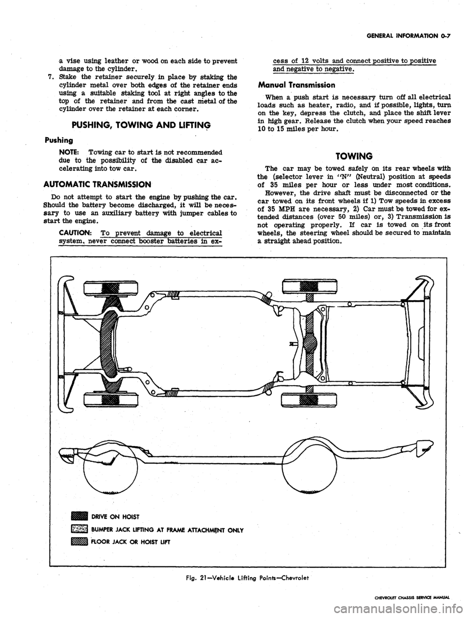
DRIVE ON HOIST
BUMPER JACK LIFTING AT FRAME ATTACHMENT ONLY
FLOOR JACK OR HOIST LIFT
Fig.
21-Vehicle Lifting Pointe-Chevroiet
CHEVROLET CHASSIS SERVICE MANUAL
Page 53 of 659
HEATER AND AIR CONDITIONING 1A-30
Leak Detector
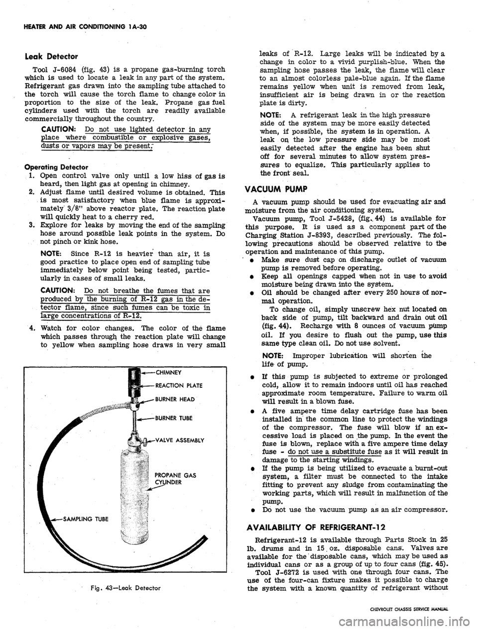
Tool J-6084 (fig. 43) is a propane gas-burning torch
which is used to locate a leak in any part of the system.
Refrigerant gas drawn into the sampling tube attached to
the torch will cause the torch flame to change color in
proportion to the size of the leak. Propane gas fuel
cylinders used with the torch are readily available
commercially throughout the country.
CAUTION: Do not use lighted detector in any
place where combustible or explosive gases,
dusts or vapors may be present;
Operating Detector
1.
Open control valve only until a low hiss of gas is
heard, then light gas at opening in chimney.
2.
Adjust flame until desired volume is obtained. This
is most satisfactory when blue flame is approxi-
mately 3/8" above reactor plate. The reaction plate
will quickly heat to a cherry red.
3.
Explore for leaks by moving the end of the sampling
hose around possible leak points in the system. Do
not pinch or kink hose.
NOTE: Since R-12 is heavier than air, it is
good practice to place open end of sampling tube
immediately below point being tested, partic-
ularly in cases of small leaks.
CAUTION: Do not breathe the fumes that are
produced by the burning of R-12 gas in the de-
tector flame, since such fumes can be toxic in
large concentrations of R?»12.
4.
Watch for color changes. The color of the flame
which passes through the reaction plate will change
to yellow when sampling hose draws in very small
CHIMNEY
REACTION PLATE
BURNER HEAD
Fig.
43—Leak Detector
leaks of R-12. Large leaks will be indicated by a
change in color to a vivid purplish-blue. When the
sampling hose passes the leak, the flame will clear
to an almost colorless pale-blue again. If the flame
remains yellow when unit is removed from leak,
insufficient air is being drawn in or the reaction
plate is dirty.
NOTE: A refrigerant leak in the high pressure
side of the system may be more easily detected
when, if possible, the system is in operation. A
leak on the low pressure side may be most
easily detected after the engine has been shut
off for several minutes to allow system pres-
sures to equalize. This particularly applies to
the front seal.
VACUUM PUMP
A vacuum pump should be used for evacuating air and
moisture from the air conditioning system.
Vacuum pump, Tool J-5428, (fig.. 44) is available for
this purpose. It is used as a component part of the
Charging Station J-8393, described previously. The fol-
lowing precautions should be observed relative to tbe
operation and maintenance of this pump.
' • Make sure dust cap on discharge outlet of vacuum
pump is removed before operating.
• Keep all openings capped when not in use to avoid
moisture being drawn into the system.
• Oil should be changed after every 250 hours of nor-
mal operation.
To change oil, simply unscrew hex nut located on
back side of pump, tilt backward and drain out oil
(fig. 44). Recharge with 8 ounces of vacuum pump
oil.
If you desire to flush out the pump, use this
same type clean oil. Do not use solvent.
NOTE: Improper lubrication will shorten the
life of pump.
• If this pump is subjected to extreme or prolonged
cold, allow it to remain indoors until oil has reached
approximate room temperature. Failure to warm oil
will result in a blown fuse.
• A five ampere time delay cartridge fuse has been
installed in the common line to protect the windings
of the compressor. The fuse will blow if an ex-
cessive load is placed on the pump. In the event the
fuse is blown, replace with a five ampere time delay
fuse - do not use a substitute fuse as it will result in
damage to the starting windings.
• If the pump is being utilized to evacuate a burnt-out
system, a filter must be connected to the intake
fitting to prevent any sludge from contaminating the
working parts, which will result in malfunction of the
pump.
• Do not use the vacuum pump as an air compressor.
AVAILABILITY OF REFRIGERANT-12
Refrigerant-12 is available through Parts Stock in 25
lb.
drums and in 15 oz. disposable cans. Valves are
available for
the"
disposable cans, which may be used as
individual cans or as a group of up to four cans (fig. 45).
Tool J-6272 is used with one through four cans. The
use of the four-can fixture makes it possible to charge
the system with a known quantity of refrigerant without
CHEVROLET CHASSIS SERVICE MANUAL
Page 136 of 659
CORVETTE BODY 1B-29
CUSHION
CUSHION ASNi.^ty** ACCESS
#2 BODY BRACKET
( 67 ONLY)
SHIM
( 37 POSITION).
CUSHION ASM.
( 37)
SHIM
( 67 POSITION)
CUSHION
( 37 ONLY)
#1 BODY BRACKET
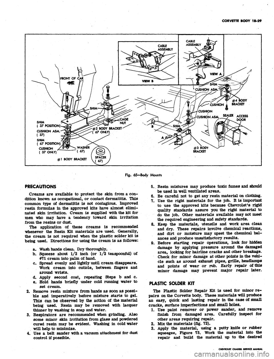
Fig.
65—Body Mounts
PRECAUTIONS
Creams are available to protect the skin from a con-
dition known as occupational, or contact dermatitis. This
common type of dermatitis is not contagious. Improved
resin formulas in the approved kits have almost elimi-
nated skin irritation. Cream is supplied with the kit for
men who may have a tendency toward skin irritation
from the resins or dust.
The application of these creams is recommended
whenever the Resin Kit materials are used. Generally,
the cream is not required when the plastic solder kit is
being used. Directions for using the cream is as follows:
a. Wash hands clean. Dry thoroughly.
b.
Squeeze about 1/2 inch (or 1/2 teaspoonful) of
#71 cream into palm of hand.
c. Spread evenly and lightly until cream disappears.
Work cream into cuticle, between fingers and
around wrists.
d. Apply second coat, repeating Steps b and c.
e. Hold hands briefly under cold running water to
set cream.
2.
Remove resin mixture from hands as soon as possi-
ble and imperatively before mixture starts to gel.
This can be observed by the action of the material
being used. Resin may be removed with lacquer
thinner by washing in soap and water.
3.
Respirators are recommended when grinding. Also
some minor skin irritation from glass and powdered
cured resin may be evident. Washing in cold water
will help to minimize.
4.
Use a belt sander with a vacuum attachment for dust
control if possible.
5. Resin mixtures may produce toxic fumes and should
be used in well ventilated areas.
6. Be careful not to get any resin material on clothing.
7. Use the right materials for the job. It is important
to use the approved kits because Chevrolet's rigid
quality standards assure you the right material to
do the job. Other materials available may not meet
the required engineering and safety standards.
8. Keep the materials, utensils and work area clean
and dry. These repairs involve chemical reactions,
and dirt or moisture may upset the chemical bal-
ances and produce unsatisfactory results.
9. Before starting repair operations, look for hidden
damage by applying pressure around the damaged
area, looking for hairline cracks and other breakage.
Check for minor damage at other points in the vehi-
cle such as around exhaust pipes, grille, headlamps
and points of wear or rub. Early repair of this
minor damage may prevent major repair later.
PLASTIC SOLDER
KIT
The Plastic Solder Repair Kit is used for minor re-
pairs on the Corvette body. These materials will produce
an easy, quick and lasting repair in the case of small
cracks, surface imperfections and small holes.
1.
Use paint remover or power sander, and remove
finish from damaged area. Carefully inspect for
other areas requiring repair.
2.
Mix the materials (fig. 72).
3.
Apply the material, using a putty knife or rubber
squeegee, Figure 73. Work the material into the
repair and build the material up to the desired
CHEVROLET CHASSIS SERVICE
Page 154 of 659
CORVETTE BODY
1B-47
REAR
BOW
ASSY.
VIEW
C
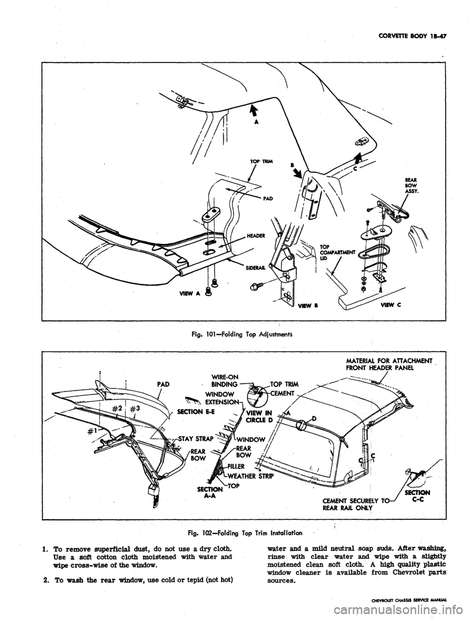
Fig.
101—Folding
Top
Adjustments
MATERIAL
FOR
ATTACHMENT
FRONT HEADER PANEL
PAD
WIRE-ON
BINDING
WINDOW
EXTENS
SECTION
E-E
AY STRAP
SECTION
A-A
CEMENT SECURELY
REAR RAIL ONLY
Fig.
102—Folding
Top
Trim Installation
1.
To
remove superficial dust,
do not use a
dry cloth.
Use
a
soft cotton cloth moistened with water
and
wipe cross-wise
of
the window.
2.
To
wash
the
rear window,
use
cold or tepid (not hot)
water
and a
mild neutral soap suds. After washing,
rinse with clear water
and
wipe with
a
slightly
moistened clean soft cloth.
A
high quality plastic
window cleaner
is
available from Chevrolet parts
sources.
CHEVROLET
Oi
SERVia
Page 159 of 659
CORVETTE BODY 1B-52
and pull weatherstrip and trim from rear bow.
Section A-A shows installed position of these com-
ponents. Refer also to figure 105.
installation
1.
Find and mark center of header, #3 bow, rear bow
and leading and trailing edges of top trim. Align
these marks during installation and recheck their
alignment from time to time while installation is in
progress, especially during tacking or stapling.
2.
Assemble top trim and weatherstrip to rear bow,
referring to Section A-A and Figure 105. Note that
filler strip locks this assembly together and goes
in last. Align center marks.
3.
If new pads are required, install at this time, align-
ing with marks made when old pads were removed.
Figure 106 shows pad construction; Figure 107 shows
pad installed.
4.
Install top trim-rear bow assembly on top frame
with four screws removed at disassembly.
5.
Lock down rear bow in desired "top up" position.
Pull up stay straps and staple or tack to #3 bow
(fig. 108).
6. Pull leading edge of trim iip to header and align
center marks. Smooth out fabric and clamp, tack
or staple temporarily to header.
7.
Draw window extension up to #3 bow, aligning cen-
tering marks. Turn an ample amount of fabric under
and tack to #3 bow. Apply neoprene trim cement,
GM Part #3695016 or equivalent, to area shown in
View D of Figure 102. Follow directions on package.
8. Draw roof portion of trim over #3 bow, align marks
and tack on staple.
9. Trim off excess material and install wire-on binding
as shown in Figure 109 and View D of Figure 102.
Install binding caps.
10.
Remove temporary clamps or fastenings holding trim
to header.
11.
With header locked down, pull trim assembly up tight
and mark for final installation.
12.
Apply trim cement to header and rear side rail.
13.
Release header from windshield. Tack or staple trim
to header (fig. 103).
14.
Apply trim to rear side frame, previously cemented.
15.
Install weatherstrips which were removed at dis-
assembly and install retaining screws in header
weatherstrip.
16.
Make any adjustments necessary, following instruc-
tions listed under Folding Top—Adjustments.
FRAME AND LINKAGE
Figure 110 illustrates construction features of the
folding top frame and linkage. Various cross sections in
Figure 110 show the pivoting joints and their assembly.
If an operation is being performed which requires
removal of folding top trim, follow directions in this
section. The entire frame assembly may be removed and
replaced as a unit. Follow instructions for Folding Top
Trim and Rear Window Assembly and Top Assembly—
Removal and Installation.
The pivoting joints should be lubricated with light
machine oil once a year. Apply oil sparingly so as not
to stain top trim.
WEATHERSTRIP
Side Rail Weatherstrip
Figure 111 illustrates installation of side rail weather-
strip which acts to seal window opening. The weather-
strip is held in place by studs which are part of the
weatherstrip assembly, and by neoprene base cement
which is applied between weatherstrip and side rail
surface.
When replacing weatherstrip remove all rust, old
cement and foreign material from the surfaces to be
cemented, to assure successful bonding. Use only good
quality neoprene cement suitable for weatherstrip
application.
Header Weatherstrip
Weatherstrip assembly is retained to the header panel
by a combination of studs, sheet metal screws and special
fasteners as shown in Figure 112, along with neoprene
base weatherstrip cement.
Figure 99 shows' a cross section of weatherstrip taken
through a special fastener. To replace fastener, rotate
ninety degrees to align fastener head with slot. Follow
directions for cementing in the Side Rail Weatherstrip
instructions preceding this write up.
ADDING HARDTOP (ROOF PANEL ASSEMBLY)
An available roof panel assembly (hardtop) complete
can be added to convertible model Corvettes. The hard-
ware is included with the panel assembly.
Reworking of a plastic part (one for each side of the
roof panel) can be used as a marker for drilling of two
required holes in the folding top compartment lid* Hard-
ware is attached at four locations — two on the lid and
two (one each side) at the lock pillar area as follows:
1.
Rework two plastic retainers (#6280765) (used on
Chevrolet and Corvair door inner panels for trim
retention) as shown by Figure 113.
2.
Slide the reworked plastic retainers into the bolt re-
tainer slots on each side of the hardtop rear bow
(position plastic tip inboard).
3.
Mark the hardtop reveal molding at the approximate
location of the two plastic retainers,
4.
Mark the tips of the two plastic retainers with a
china marker pencil.
5.
Close the soft top compartment lid.
6. With aid of an ^assistant, position front of hardtop
onto header and lower onto vehicle. Do not fasten
latches at windshield header.
7.
Apply hand pressure at reveal molding marks.
8. Mark roof panel attachment hole location at each
lock pillar area (fig. 114).
9. With aid of an assistant, lift roof panel straight up
off body and set roof panel aside.
10.
Mark the drill position at the four china marks with
a center punch.
11.
Place a 2" x 4" board under the top compartment lid
to prevent drill damage to folding top material. Make
certain the compartment lid is securely locked
before drilling.
12.
Drill 1/8" pilot hole at the 4 marked locations.
CHEVROLET CHASSIS SERVICE MANUAL
Page 172 of 659
FRONT SUSPENSION 3-8
REPAIR PROCEDURES
Unless otherwise indicated all repair procedures will
apply to all five vehicles covered in this manual.
CAUTION: During any operations which in-
clude breaking the ball stud loose from the
knuckle boss extreme care must be used to as-
sure that the ball stud seal is not damaged or
cut. A recommended way to loosen the stud is to
place a flat bar stock against the knuckle boss
and strike the bar rather than the knuckle.
FRONT BRAKE DRUM-CHEVROLET, CAMARO,
CHEVELLE, CHEVY It
Removal
1.
Remove hub caps, partially loosen wheel nuts and
raise vehicle from floor. Remove wheel nuts and
wheel.
2.
Remove brake drum. In some cases it may be nec-
essary to back off brake adjustment because of
scored drum or unevenly worn brake linings.
3.
Check brake drum for concentricity, damaged pilot
diameter or scored braking surface. Lightly sand
braking surface and wipe clean.
Installation
1.
Install drum over hub bolts making sure alignment
dowel on drum web indexes with hole in wheel hub.
This will assure proper drum alignment with hub
bolts and hub pilot diameter.
2.
Install wheel and partially tighten wheel nuts.
3.
Re-adjust brake shoes to original setting. It may be
necessary to re-adjust brake shoes on both front
and/or rear wheels to assure balanced brake adjust-
ment. See Section 5 for brake adjustment procedure.
4.
Lower vehicle to floor, tighten hub wheel nuts and in-
stall hub cap.
FRONT WHEEL HUB
Replacement
1.
Remove hub caps, break loose the wheel stud nuts
VM" DIA. PIPE OR ARBOR
>l
INNER CUP
OUTER CUP
JL
RADIUS
e^
Fig.
10 - Pressing Front Hub Bolts (Typical)
Fig.
11 - Front Wheel Bearing Cop Removers
and raise vehicle. Remove wheel nuts, wheel and
tire and brake drum or (on Corvette) brake caliper
and brake disc.
NOTE:
On the Corvette, the hub and brake disc
are serviced as a complete assembly.
2.
Pry out hub grease cap, cotter pin, spindle nut and
washer,
and
remove hub. Do not drop wheel bearings.
3.
Reverse this procedure to install.
Replacement of Wheel Hub Bolts
It may be necessary to replace damaged wheel hub
bolts.
In this case, service the hub in the following
manner.
1.
Remove the hub bolts with a press or hammer.
These bolts are not peened into the hub. Do not
damage wheel mounting surface on hub flange.
2.
Install new serrated bolt into hole in
hub.
Tap lightly
with a hammer to start bolt serrations in hole, mak-
ing sure that bolt is square with hub flange.
3.
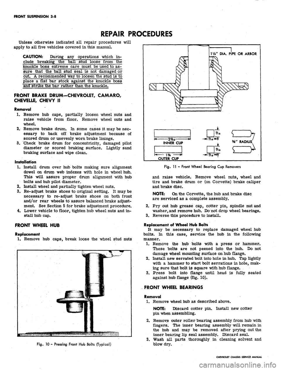
Press bolt into flange until head is fully seated
against hub flange (fig. 10).
FRONT WHEEL BEARINGS
Removal '
1.
Remove wheel hub as described above.
NOTE: Discard cotter pin. Install new cotter
pin when assembling.
2.
Remove outer roller bearing assembly from hub with
fingers. The inner bearing assembly will remain in
the hub and may be removed after prying out the
inner bearing lip seal assembly. Discard seal.
3.
Wash all parts thoroughly in cleaning solvent and
blow dry.
CHEVROLET CHASSIS SERVICE MANUAL
Page 179 of 659
FRONT SUSPENSION 3-15
4.
Insert Spring Compressor J-
6874-
4-
5 with Adapters
J-6874-8-9 into upp^r spring tower so that lower
MU"
bolt fits into shock absorber mounting holes in
spring seat (fig. 23). Secure the two lower studs to
the spring seat with nuts.
5.
Fit the tool upper pilot to top of spring and compress
spring by tightening upper nut (fig. 24). Compress
spring until screw is bottomed out.
6. Remove lower spring seat retaining nuts, lift spring
and seat assembly from control arm and guide it
down and out through fender skirt (fig. 25).
Spring Seat Replacement (Fig. 26)
1.
Release spring tension and disconnect spring com-
pressor from spring seat.
2.
Install new spring seat to spring compressor.
Installation
1.
If spring is to be replaced, install new spring into
tool and compress spring until screw is bottomed
out.
NOTE: Spring coil ends must be against spring
stops in upper and lower seats.
2.
Lift spring and tool assembly into place and position
so that the upper spring stop is inboard.
NOTE: Locating tab on upper spring seat may
be flattened before reinstalling spring.
3.
Install lower spring seat to control arm and torque
nuts as shown in the Specifications.
4.
Loosen spring compressor until spring is properly
seated in upper spring tower and remove.
5.
Install shock abosrber as outlined under Shock Ab-
sorber—Installation in this section.
Corvette
Removal
1.
With car on suitable hoist or jack, (support vehicle
by frame so control arms may swing free) remove
wheel and tire assembly, stabilizer bar and shock
absorber. Loosen the lower ball joint to steering
knuckle nut, and the' two lower control arm cross
shaft bushing bolts.
2.
Place Tool J-6874-1 across top of sixth coil (ap-
prox.),
then loosely secure Tool J-6874-2 to the up-
per shoe, with attaching capscrews and lock washers.
The upper shoe "V" notch and lower shoe raised land
should contact spring.
3.
Insert Tool J-6874 up through center of spring and
attach to upper and lower shoe assembly.
4.
Position spacers under shock absorber mounting hole
and against bottom of lower control arm. Install
special bearing washer and Tool J-6874-5. Locate
bearing against spacer and large washer against
bearing. Feed screw up through large washer bear-
ing and spacer and thread into Tool J-6874 and
tighten snugly (fig. 22).
5.
Center shoe assembly on spring and tighten screw
until a very slight compression is placed on spring
(fig. '22). Then firmly tighten down the two cap-
screws securing the upper and lower shoes to lock
these shoes to spring.
6. Turn head of screw until spring is compressed just
enough to clear the spring tower, then remove the
lower ball joint to steering knuckle nut (fig. 22).
NOTE: It may be necessary to assist the
spring out of the spring tower with a pry bar or
a similar tool.
7.
Disconnect the lower ball joint from the steering
knuckle and lower the control arm with the com-
pressed spring. Immediately release compression
on spring by backing off long screw. Release spring
and tool and withdraw spring.
CAUTION: The spring force under compres-
sion is very large. Exercise every safety pre-
caution when performing this operation to see
that individuals and materials subject to damage
are removed from the path of the spring when
the control arm is being lowered. Also, the
compressed spring
be relaxed immedi-
ately after lowering the control arm to reduce
the time of exposure to the large compressive
force.
Installation
1.
Position spring with closely coiled end up. Place
Tool J-6874-1 across the top of the sixth coil (ap-
prox.) then loosely secure Tool J-6874-2 to the
upper shoe with attaching capscrews and lock wash-
ers.
The upper shoe MV" notch and lower shoe
raised land should contact spring.
2.
Insert Tool J-6874 up through center of spring and
attach to upper and lower shoe assembly with bolt
and nut.
3.
Set spring in its seat on the lower control arm.
4.
Position spacers centrally under shock absorber
mounting hole and against bottom of lower control
arm. Install bearing, large washer and Tool
J-6874-5.
Locate bearing against spacer and large
washer against bearing. Feed the screw up through
large washer, bearing and spacer and thread into
yoke rod. Tighten snugly, but do not start to draw
down yet
5.
Center the shoe assembly on the spring and tighten
the lag screw until a very slight compression is
placed on spring, then firmly tighten down the two
capscrews securing the upper and lower shoes. This
will lock the shoes to the coil spring.
6. Turn head of screw until spring is compressed just
enough to clear the spring tower.
NOTE: It may be necessary to assist the
spring into the spring tower with a pry bar or
similar tool.
7.
Immediately install the lower ball joint into steering
knuckle and secure in place with attaching nut.
8. Release compression on spring and at the same time
use a drift to guide the coil spring into its proper
seat. End of coils must be 3/8" from coil stops in
spring seat.
9. Tighten the lower ball joint to steering knuckle nut
and lock with cotter key.
10.
Install shock absorber and stabilizer bar.
11.
Install wheel, tire and drum assembly.
12.
Remove car from hoist or jack stands.
13.
Tighten the two lower control cross shaft bushing
bolts to 45-55 lbs. ft. torque.
NOTE: If a suitable adjustable jack-stand is
CHEVROLET CHASSIS SERVICE MANUAL
Page 185 of 659
FRONT SUSPENSION 3-21
Chevy II
Removal
1.
Support control arm on Tool J-7 574-4 and insert
Spacer J-9514 (fig. 34).
2,
Press bushing out with Tool J-9226 and Handle
J-7079-2 (fig. 34).
Installation
With Spacer J-9514 still in control arm, invert control
arm and press in new bushing with Tool, J-7474-2 and
Handle J-7079-2 until bushing is fully seated.
CAUTION: It should be noted that control arm
bushing diameters are unequal and bushing must
be pressed into position through larger diameter
only.
CROSS SHAFT AND/ON BUSHINGS
Corvette
Removal
1.
Remove bolt, lock washer and collar from each end
of cross shaft.
2.
Thread a 7/16 x 20 capscrew (furnished with Tool
J-5888) to the bottom of the threads in one end of the
cross shaft.
3.
Support control arm in an arbor press on Tool
J-5888-3,
as shown in Figure 35.
NOTE:
Be certain bushing flange does not
contact support.
4.
Press on cap screw until bushing is free of control
arm. Discard bushing.
5. Remove cap screw from cross shaft. Insert it in
other end of shaft. Invert control arm on support.
Again be certain bushing flange does not contact
support.
6. Press on cap screw until bushing is free of control
arm. Discard bushing.
Installation
1.
With cross shaft in control arm and Tool J-7052-1
in position, place control arm on Tool J-5888-3.
Hand start bushing into control arm and over end of
cross shaft.
NOTE:
The end of the shaft with the two bolt
holes should be toward front of control arm.
2.
Install Tool J-7052-5 over bushing. Be certain
three-piece spacer is not over-lapping bushing holes
in control arm.
3.
Press bushing into control arm until flange contacts
control arm (fig. 36).
4.
Invert arm in press and repeat the process on the
other bushing. After installation, cross shaft should
be free enough to be rotated by hand.
5. Install collar, lock washer and cap screw in each end
of cross shaft. Tighten to torque shown in Specifica-
tions after spring installation.
UPPER CONTROL ARM SPHERICAL JOINT
Chevrolet, Chevelle, Comoro and Corvette
Inspection
The upper spherical joint is checked for wear by
checking the torque required to rotate the ball stud in the
assembly. After performing the first four steps under
"Replacement" below, install a stud nut on the stud and
measure the torque required to turn the stud in the as-
sembly with a torque wrench. Specified torque for a new
joint is 9 lbs. ft. If torque readings are excessively
high or low, replace the ball joint. If excessive wear is
indicated in upper joint, both upper and lower joints
should be replaced.
NOTE:
This inspection does not necessitate
upper control arm removal.
Replacement
1.
Support the vehicle weight at the outer end of the
lower control arm.
2.
Remove the wheel and tire assembly.
3.
Remove cotter pin and nut from upper control arm
ball stud.
4.
Remove the stud from knuckle.
5. Cut off the ball joint rivets with a chisel.
6. Install new joint and retain in place with the special
nuts and bolts supplied.
7. Reassemble ball stud to the steering knuckle.
Chevy II
Inspection
The following on-the-vehicle check is to determine ball
joint wear.
NOTE:
The upper ball joint is a loose fit when
not connected to the steering knuckle. Wear may
be checked without disassembling the ball stud
by
using'
the following procedure:
1.
While vehicle weight is still on front wheels, insert
upper control arm support as shown in Figure 14.
2.
Raise vehicle and allow wheel and tire to hang free.
3.
Measure distance from tip of ball stud to top surface
of control arm.
4.
Place adjustable jackstand under tire and raise
slightly to take up ball joint looseness.
5. Repeat Step 3 and if the difference in measurements
exceeds 3/32", the joint is excessively worn and
should be replaced.
Replacement
1.
With vehicle weight still on front wheels, install
spacer between upper control arm and frame side
rail (fig. 15). Raise vehicle.
2.
Remove wheel and tire.
3.
Disconnect stabilizer link (if present) and strut rod
at lower control arm.
4.
Remove cotter pin and nut from upper ball joint stud.
5. Break ball stud loose. Drop lower control arm,
steering knuckle and brake assembly with an adjust-
able jackstand until upper control arm ball joint is
easily accessible.
6. Using a large chisel, cut off the three ball joint re-
taining plate rivet heads. It may be necessary to
drill out rivet heads before chiseling.
CHEVROLET CHASSIS SERVICE MANUAL
Page 281 of 659
ENGINE 6-16
5.
Adjust ignition timing and carburetor idle speed and
mixture.
VALVE STEM OIL SEAL AND/OR VALVE SPRING
Replacement
1.
Remove rocker arm cover as outlined.
2.
Remove spark plug, rocker arm and push rod on the
cylinder(s) to be serviced.
3.
Apply compressed air to the spark plug hole to hold
the valves in place.
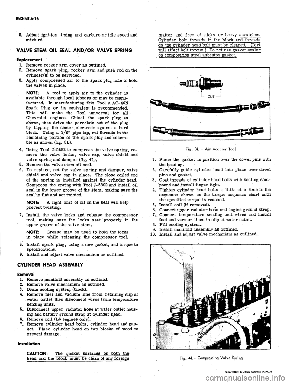
NOTE: A tool to apply air to the cylinder is
available through local jobbers or may be manu-
factured. In manufacturing this Tool a AC-46N
Spark Plug or its equivalent is recommended.
This will make the Tool universal for all
Chevrolet engines. Chisel the spark plug as
shown, then drive the porcelain out of the plug
by tapping the center electrode against a hard
block. Using a 3/8" pipe tap, cut threads in the
remaining portion of the spark ^>lug and assem-
ble as shown (fig. 3L).
4.
Using Tool J-5892 to compress the valve spring, re-
move the valve locks, valve cap, valve shield and
valve spring and damper (fig. 4L).
5.
Remove the valve stem oil seal.
6. To replace, set the valve spring and damper, valve
shield and valve cap in place. The close coiled end
of the spring is installed against the cylinder head.
Compress the spring with
Too^
J-5892 and install oil
seal in the lower groove of the stem, making sure the
seal'is flat and not twisted.
NOTE: A light coat of oil on the seal will help
prevent twisting.
7.
Install the valve locks and release the compressor
tool, making sure the locks seat properly in the
upper groove of the valve stem.
NOTE: Grease may be used to hold the locks
in place while releasing the compressor tool.
8. Install spark plug, using a new gasket, and torque to
specifications.
9. Install and adjust valve mechanism as outlined.
CYLINDER HEAD ASSEMBLY
Removal
1.
Remove manifold assembly as. outlined.
2.
Remove valve mechanism as outlined.
3.
Drain cooling system (block).
4.
Remove fuel and vacuum line from retaining clip at
water outlet then disconnect wires from temperature
sending units.
5.
Disconnect upper radiator hose at water outlet hous-
ing and battery ground strap at cylinder head.
6. Remove coil (L6 engines only).
7.
Remove cylinder head bolts, cylinder head and gas-
ket. Place cylinder head on two blocks of wood to
prevent damage.
Installation
CAUTION: The gasket surfaces on both the
head and the block must be clean of any foreign
matter and free of nicks or heavy scratches.
Cylinder bolt threads in the block and threads
on the cylinder head bolt must be cleaned. (Dirt
will affect bolt torque.) Do not use gasket sealer
on composition steel asbestos gasket.
Fig. 3L -
AIF
Adapter Tool
1.
Place the gasket in position over the dowel pins with
the bead up.
2.
Carefully guide cylinder head into place over dowel
pins and gasket.
3.
Coat threads of cylinder head bolts with sealing com-
pound and install finger tight.
4.
Tighten cylinder head bolts a little at a time in the
sequence shown on the torque sequence chart until
the specified torque is reached.
5.
Install coil (if removed).
6. Connect upper radiator hose and engine ground strap.
7.
Connect temperature sending unit wires and install
fuel and vacuum lines in clip at water outlet.
8. Fill cooling system.
•
9. Install manifold assembly as outlined.
10.
Install and adjust valve mechanism as outlined.
Fig.
4L
- Compressing Valve Spring
CHEVROLET CHASSIS SERVICE MANUAL
Page 294 of 659
ENGINE 6-29
an extent that the return spring can no longer push
the plunger back up to working position. Probable
causes are:
a. Excessive varnish or carbon deposit causing ab-
normal stickiness.
b.
(Sailing or "pick-up" between plunger and bore of
lifter body, usually caused by an abrasive piece of
dirt or metal wedging between plunger and lifter
body.
2.
Moderate Rapping Noise--Probable causes are:
a. Excessively high leakdown rate.
b.
Leaky check valve seat.
c. Improper adjustment.
3.
General Noise Throughout the Valve Train-rThis
will, in almost all cases, be a definite indication of
insufficient oil supply, or improper adjustment.
4.
Intermittent Clicking—Probable causes are:
a. A microscopic piece of dirt momentarily caught
between ball seat and check valve ball.
b.
In rare cases, the ball itself may be out-of-round
or have a flat spot.
c. Improper adjustment.
In most cases where noise exists in one or more lifters
all lifter units should be removed, disassembled, cleaned
in a solvent, reassembled, and reinstalled in the engine.
If dirt, corrosion, carbon, etc. is shown to exist in one
unit, it more than likely exists in all the units, thus it
would only be a matter of time before all lifters caused
trouble.
Removal
1.
Remove intake manifold as outlined.
2.
Remove valve mechanism as outlined.
3.
Remove valve lifters.
NOTE: Place valve lifters in a rack so they
may be reinstalled in the same location.
Installation
1.
Install valve lifters.
NOTE: Whenever new valve lifters are being
installed coat foot of valve lifters with Molykote
or its equivalent.
2.
Install intake manifold as outlined.
3.
Install and adjust valve mechanism as outlined.
VALVE STEM OIL SEAL AND/OR VALVE SPRING
Replacement
1.
Remove rocker arm cover(s) as outlined.
2.
Remove spark plug, rocker arm and push rod on the
cylinders to be serviced.
3.
Apply compressed air to the spark plug hole to hold
tl*e valves in place.
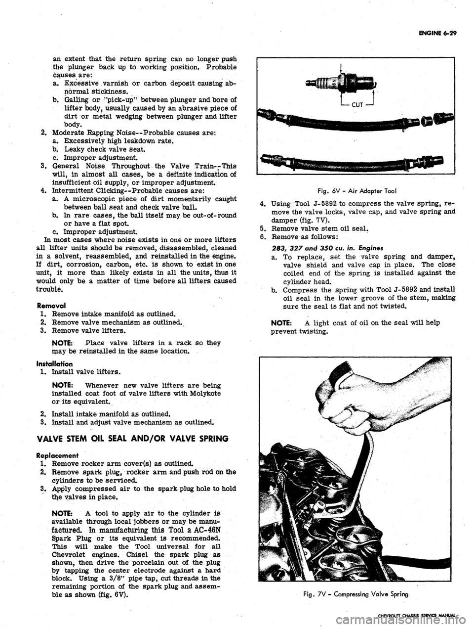
NOTE: A tool to apply air to the cylinder is
available through local jobbers or may be manu-
factured. In manufacturing this Tool a AC-46N
Spark Plug or its equivalent is recommended.
This will make the Tool universal for all
Chevrolet engines. Chisel the spark plug as
shown, then drive the porcelain out of the plug
by tapping the center electrode against a hard
block. Using a 3/8" pipe tap, cut threads in the
remaining portion of the spark plug and assem-
ble as shown (fig. 6V).
Fig.
6V - Air Adapter Tool
4.
Using Tool J-5892, to compress the valve spring, re-
move the valve locks, valve cap, and valve spring and
damper (fig. 7V).
5.
Remove valve stem oil seal.
6. Remove as follows:
283, 327 and 350 eu. in.
Engines
a. To replace, set the valve spring and damper,
valve shield and valve cap in place. The close
coiled end of the spring is installed against the
cylinder head.
b.
Compress the spring with Tool J-5892 and install
oil seal in the lower groove of the stem, making
sure the seal is flat and not twisted.
NOTE: A light coat of oil on the seal will help
prevent twisting.
Fig.
7V - Compressing Valve Spring
CHEVROLET CHASSIS SERVICE MANUAL