jump start CHEVROLET CAMARO 1967 1.G Chassis Workshop Manual
[x] Cancel search | Manufacturer: CHEVROLET, Model Year: 1967, Model line: CAMARO, Model: CHEVROLET CAMARO 1967 1.GPages: 659, PDF Size: 114.24 MB
Page 9 of 659

GENERAL INFORMATION 0-7
a vise using leather or wood on each side to prevent
damage to the cylinder,
7. Stake the retainer securely in place by staking the
cylinder metal over both edges of the retainer ends
using a suitable staking tool at right angles to the
top of the retainer and from the cast metal of the
cylinder over the retainer at each corner.
PUSHING, TOWING AND LIFTING
Pushing
NOTE:
Towing car to start is not recommended
due to the possibility of the disabled car ac-
celerating into tow car.
AUTOMATIC TRANSMISSION
Do not attempt to start the engine by pushing the car.
Should the battery become discharged, it will be neces-
sary to use an auxiliary battery with jumper cables to
start the engine.
CAUTION: To prevent damage to electrical
system, never connect booster batteries in ex-
cess of 12 volts and connect positive to positive
and negative to negative.
Manual Transmission
When a push start is necessary turn off all electrical
loads such as heater, radio, and if possible, lights, turn
on the key, depress the clutch, and place the shift lever
in high gear. Release the clutch when your speed reaches
10 to 15 miles per hour.
TOWING
The car may be towed safely on its rear wheels with
the (selector lever in "N" (Neutral) position at speeds
of 35 miles per hour or less under most conditions.
However, the drive shaft must be disconnected or the
car towed on its front wheels if 1) Tow speeds in excess
of 35 MPH are necessary, 2) Car must be towed for ex-
tended distances (over 50 miles) or, 3) Transmission is
not operating properly. If car is towed on its front
wheels, the steering wheel should be secured to maintain
a straight ahead position.
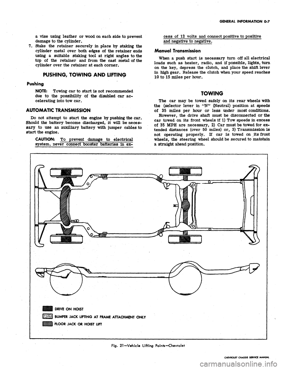
DRIVE ON HOIST
BUMPER JACK LIFTING AT FRAME ATTACHMENT ONLY
FLOOR JACK OR HOIST LIFT
Fig.
21-Vehicle Lifting Pointe-Chevroiet
CHEVROLET CHASSIS SERVICE MANUAL
Page 267 of 659

ENGINE 6-2
remotely at the starter, with a special jumper
cable or other means, the primary distributor
lead must be disconnected from the negative
post on the coil and the ignition switch must be
in the "ON" position. Failure to do this will
result in a damaged grounding circuit in the
ignition switch.
3.
Crank engine through at least four compression
strokes to obtain highest possible reading.
4.
Check and record compression of each cylinder.
5.
If one or more cylinders read low tor uneven, inject
about a tablespoon of engine oil on top of pistons
in low reading cylinders (through spark plug
port).
Crank engine several times and recheck
compression.
• If compression comes up but does not necessarily
reach normal, rings are worn.
• If compression does not improve, valves are
burnt, sticking or not seating properly.
• If two adjacent cylinders indicate low compres-
sion and injecting oil does not increase compres-
sion, the cause may be a head gasket leak between
the cylinders. Engine coolant and/or oil in cylin-
ders could result from this defect.
NOTE: If a weak cylinder cannot be located
with the compression check, see "Cylinder Bal-
ance Test" under "Additional Checks and Adjust-
ments" in this section.
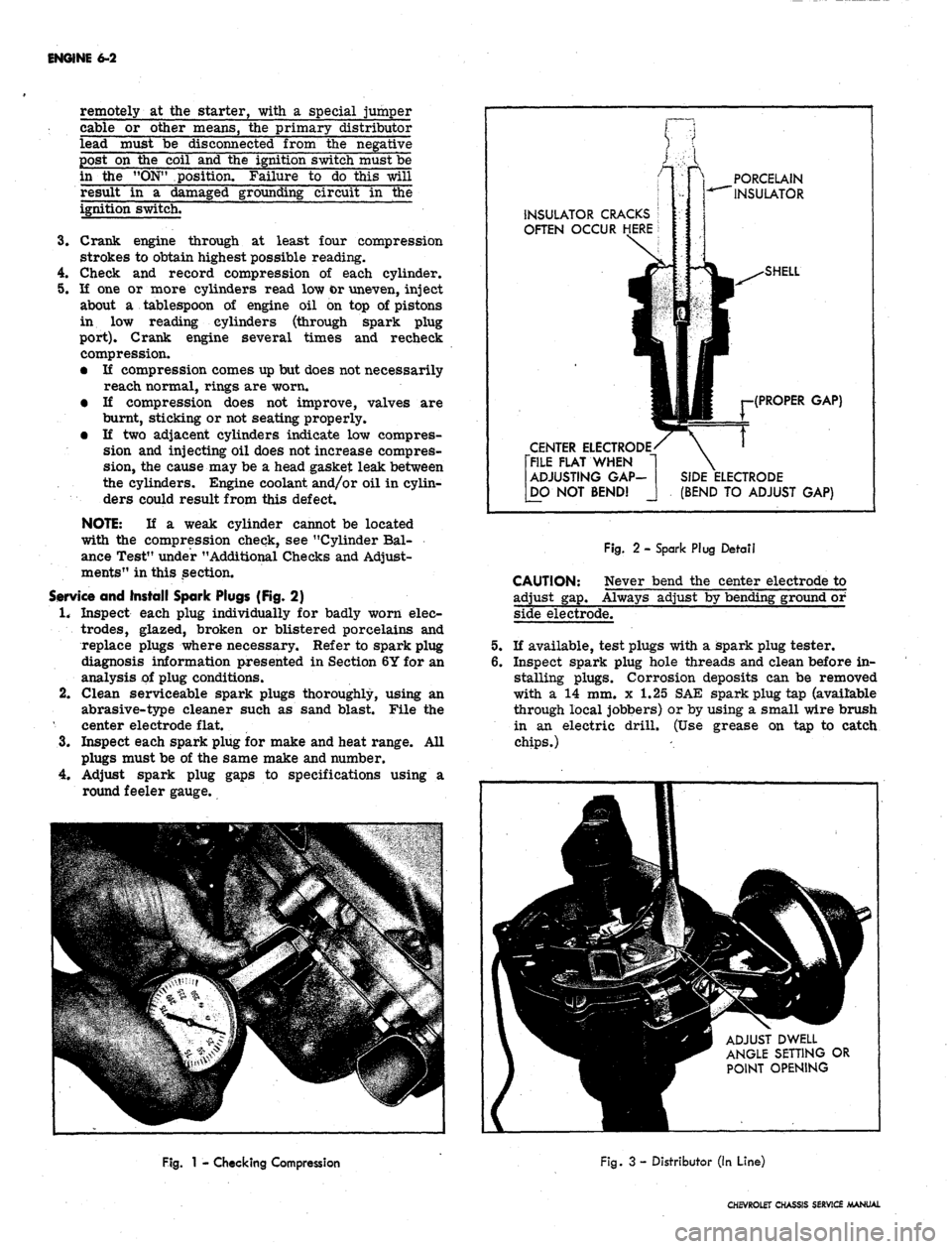
Service and Install Spark Plugs (Fig. 2)
1.
Inspect each plug individually for badly worn elec-
trodes,
glazed, broken or blistered porcelains and
replace plugs where necessary. Refer to spark plug
diagnosis information presented in Section 6Y for an
analysis of plug conditions.
2.
Clean serviceable spark plugs thoroughly, using an
abrasive-type cleaner such as sand blast. File the
center electrode flat.
3.
Inspect each spark plug for make and heat range. All
plugs must be of the same make and number.
4.
Adjust spark plug gaps to specifications using a
round feeler gauge.
PORCELAIN
INSULATOR
INSULATOR CRACKS
OFTEN OCCUR HERE
CENTER ELECTRODE
[FILE FLAT WHEN
ADJUSTING GAP-
[DO NOT BEND!
(PROPER GAP)
(BEND TO ADJUST GAP)
CAUTION:
adjust gap.
Fig.
2 - Spark Plug Detail
Never bend the center electrode to
Always adjust by bending ground or
side electrode.
If available, test plugs with a spark plug tester.
Inspect spark plug hole threads and clean before in-
stalling plugs. Corrosion deposits can be removed
with a 14 mm. x 1.25 SAE spark plug tap (available
through local jobbers) or by using a small wire brush
in an electric drill. (Use grease on tap to catch
chips.)
ADJUST DWELL
ANGLE SETTING OR
POINT OPENING
Fig.
1 - Checking Compression
Fig.
3 - Distributor (In Line)
CHEVROLET CHASSIS SERVICE MANUAL
Page 319 of 659

ENGINE FUEL 6M-11
dripping fuel, but a leak on the suction would not be ap-
parent except for its effect of reducing volume of fuel on
the pressure side.
1.
Tighten any loose line connections and look for bends
or kinks in lines.
2.
Disconnect fuel pipe at carburetor. Disconnect dis-
tributor to coil primary wire so that engine can be
cranked without firing. Place suitable container at
end of pipe and crank engine a few revolutions. If
little or no gasoline flows from open end of pipe then
fuel pipe is clogged or pump is inoperative. Before
removing pump disconnect fuel pipe at gas tank and
outlet pipe and blow through them with an air hose
to make sure they are clear. Reconnect pipes and
retest while cranking engine.
CAUTION: Whenever the engine is cranked re-
motely at the starter, with a special jumper
cable or other means, the primary distributor
lead must be disconnected from the negative
post on the coil and the ignition switch must be
in the "ON" position. Failure to do this will
result in a damaged grounding circuit in the
ignition switch.
3.
If fuel flows from pump in good volume from pipe
at carburetor, check fuel delivery pressure to be
certain that pump is operating withint specified limits
as follows:
a. Attach a fuel pump pressure test gauge to dis-
connect end of pump to carburetor pipe.
b.
Run engine at approximately 450-1,000 rpm (on
gasoline in carburetor bowl) and note reading on
pressure gauge.
c. If pump is operating properly the pressure will
be within specifications and will remain constant
at speeds between 450-1,000 rpm. If pressure
is too low, too high, or varies materially at dif-
ferent speeds, the pump should be replaced.
Removal
1.
Disconnect fuel inlet and outlet pipes at fuel pump.
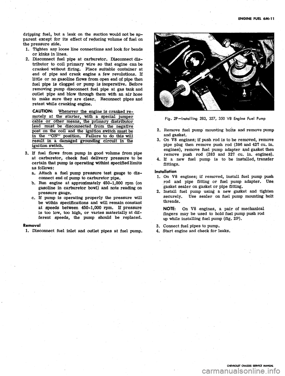
Fig.
2P-Installing 283, 327, 350 V8 Engine Fuel Pump
2.
Remove fuel pump mounting bolts and remove pump
and gasket.
3.
On V8 engines; if push rod is to be removed, remove
pipe plug then remove push rod (396 and 427 cu. in.
engines), remove fuel pump adapter and gasket then
remove push rod (283 and 327 cu. in. engines).
4.
If a new fuel pump is to be installed, transfer
fittings.
Installation
1.
On V8 engines; if removed, install fuel pump push
rod and pipe fitting or fuel pump adapter. Use.
gasket sealer on gasket or pipe fitting.
2.
Install fuel pump using a new gasket and tighten
securely. Use sealer on fuel pump mounting bolt
threads.
NOTE:
On V8 engines, a pair of mechanical
fingers may be used to hold fuel pump push rod
up while installing fuel pump (fig. 2P).
3.
Connect fuel pipes to pump.
4.
Start engine and check for leaks.
CHEVROLET CHASSIS SERVICE MANUAL
Page 336 of 659

ENGINE-ELECTRICAL 6Y-11
I
BAT
JUNCTION BLOCK
DELCOTRON
—GRQ
BATTERY
&HJVVWV
0 VA OHM TEST RELAY >
RESISTOR [ 1 d
FUSIBLE
LINK
TO CRANKING
MOTOR
Ik
REGULATOR
VOLTMETER
FUSIBLE LINK
IGN.
SWITCH
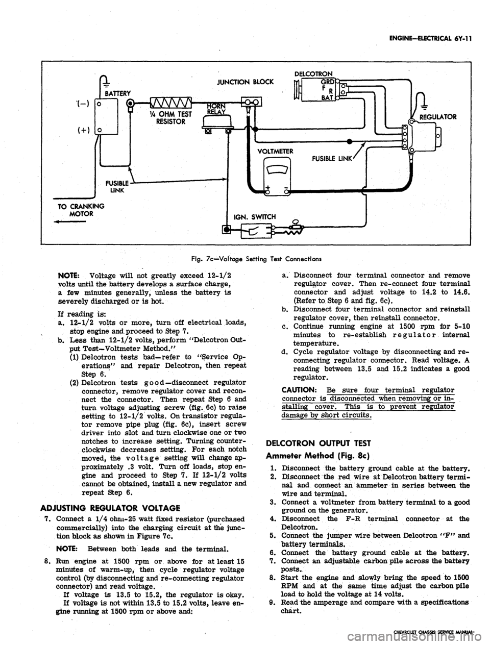
Fig.
7c—Voltage Setting Test Connections
NOTE:
Voltage will not greatly exceed 12-1/2
volts until the battery develops a surface charge,
a few minutes generally, unless the battery is
severely discharged or is hot.
If reading is:
a. 12-1/2 volts or more, turn off electrical loads,
stop engine and proceed to Step 7.
b.
Less than 12-1/2 volts, perform "Delcotron Out-
put Test-Voltmeter Method."
(1) Delcotron tests bad—refer to "Service Op-
erations" and repair Delcotron, then repeat
Step 6.
(2) Delcotron tests good—disconnect regulator
connector, remove regulator cover and recon-
nect the connector. Then repeat Step 6 and
turn voltage adjusting screw (fig. 6c) to raise
setting to 12-1/2 volts. On transistor regula-
tor remove pipe plug (fig. 6c), insert screw
driver into slot and turn clockwise one or two
notches to increase setting. Turning counter-
clockwise decreases setting. For each notch
moved, the voltage setting will change ap-
proximately .3 volt. Turn off loads, stop en-
gine and proceed to Step 7. If 12-1/2 volts
cannot be obtained, install a new regulator and
repeat Step 6.
ADJUSTING REGULATOR VOLTAGE
7. Connect a 1/4 ohm-25 watt fixed resistor (purchased
commercially) into the charging circuit at the junc-
tion block as shown in Figure 7c.
NOTE:
Between both leads and the terminal.
8. Run engine at 1500 rpm or above for at least 15
minutes of warm-up, then cycle regulator voltage
control (by disconnecting and re-connecting regulator
connector) and read voltage.
If voltage is 13.5 to 15.2, the regulator is okay.
If voltage is not within 13.5 to 15.2 volts, leave en-
gine running at 1500 rpm or above and:
a. Disconnect four terminal connector and remove
regulator cover. Then re-connect four terminal
connector and adjust voltage to i4.2 to 14.6.
(Refer to Step 6 and fig. 6c).
b.
Disconnect four terminal connector and reinstall
regulator cover, then reinstall connector.
c. Continue running engine at 1500 rpm for 5-10
minutes to re-establish regulator internal
temperature.
d. Cycle regulator voltage by disconnecting and re-
connecting regulator connector. Read voltage. A
reading between 13.5 and 15.2 indicates a good
regulator.
CAUTION: Be sure four terminal regulator
connector is disconnected when removing or in-
stalling cover. This is to prevent regulator
damage by short circuits.
DELCOTRON OUTPUT TEST
Ammeter Method (Fig. 8c)
1.
Disconnect the battery ground cable at the battery.
2.
Disconnect the red wire at Delcotron battery termi-
nal and connect an ammeter in series between the
wire and terminal.
3.
Connect a voltmeter from battery terminal to a good
ground on the generator.
4.
Disconnect the F-R terminal connector at the
Delcotron.
5. Connect the jumper wire between Delcotron "F" and
battery terminals.
6. Connect the battery ground cable at the battery.
7. Connect an adjustable carbon pile across the battery
posts.
8. Start the engine and slowly bring the speed to 1500
RPM and at the same time adjust the carbon pile
load to hold the voltage at 14 volts.
9. Read the amperage and compare with a specifications
chart.
CHEVROLET CHASSIS SERVICE MANUAL