tire size CHEVROLET CAMARO 1967 1.G Chassis Workshop Manual
[x] Cancel search | Manufacturer: CHEVROLET, Model Year: 1967, Model line: CAMARO, Model: CHEVROLET CAMARO 1967 1.GPages: 659, PDF Size: 114.24 MB
Page 197 of 659

REAR SUSPENSION AND DRIVE LINE 4-7
tioned vertically in the torque arm before ap-
plying pressure to the puller screw.
5.
Remove shim and bearing spacer from spindle
support.
6. Note size of shim used. If dial indicator reading
was more than
.008",
select a shim thinner by the
amount needed to bring end play within limits. If
dial indicator reading was less than
.001",
select a
shim thicker by the amount needed to bring end play
within limits.
NOTE: Shims are available in thicknesses from
.097"
to .148" in increments of
.003".
EXAMPLE: Bearing end play reading obtained
on dial indicator was
.011",
.003" over limit.
Bearing shim removed from spindle measures
.145".
New shim installed measures .139", .006"
smaller. End play is now decreased by .006" and
is
.005",
which is within the .001" to .008" limit.
7.
After determining shim thickness, install bearing
spacer and shim on spindle. Position spindle in
spindle support.
8. Press inner bearing race and roller assembly on
spindle as follows.
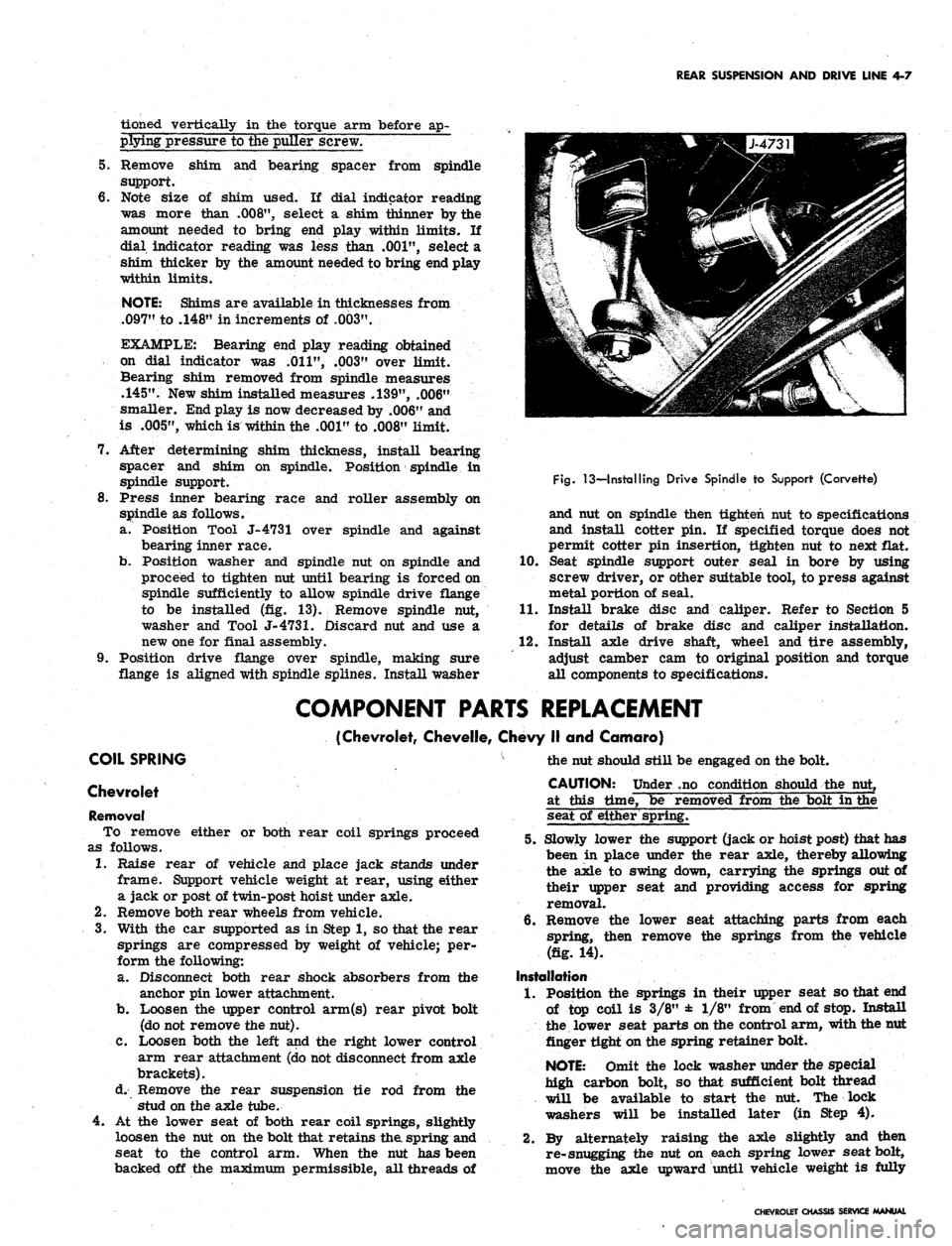
a. Position Tool J-4731 over spindle and against
bearing inner race.
b.
Position washer and spindle nut on spindle and
proceed to tighten nut until bearing is forced on
spindle sufficiently to allow spindle drive flange
to be installed (fig. 13). Remove spindle nut,
washer and Tool
J-4731.
Discard nut and use a
new one for final assembly.
9. Position drive flange over spindle, making sure
flange is aligned with spindle splines. Install washer
Fig.
13—Installing Drive Spindle to Support (Corvette)
and nut on spindle then tighten nut to specifications
and install cotter pin. If specified torque does not
permit cotter pin insertion, tighten nut to next flat.
10.
Seat spindle support outer seal in bore by using
screw driver, or other suitable tool, to press against
metal portion of seal.
11.
Install brake disc and caliper. Refer to Section 5
for details of brake disc and caliper installation.
12.
Install axle drive shaft, wheel and tire assembly,
adjust camber cam to original position and torque
all components to specifications.
COMPONENT PARTS REPLACEMENT
(Chevrolet, Chevelle, Chevy II and Camaro)
COIL SPRING
Chevrolet
Removal
To remove either or both rear coil springs proceed
as follows.
1.
Raise rear of vehicle and place jack stands under
frame. Support vehicle weight at rear, using either
a jack or post of twin-post hoist under axle.
2.
Remove both rear wheels from vehicle.
3.
With the car supported as in Step 1, so that the rear
springs are compressed by weight of vehicle; per-
form the following:
a. Disconnect both rear shock absorbers from the
anchor pin lower attachment.
b.
Loosen the upper control arm(s) rear pivot bolt
(do not remove the nut).
C. Loosen both the left and the right lower control
arm rear attachment (do not disconnect from axle
brackets).
d. Remove the rear suspension tie rod from the
stud on the axle tube.
4.
At the lower seat of both rear coil springs, slightly
loosen the nut on the bolt that retains the spring and
seat to the control arm. When the nut has been
backed off the maximum permissible, all threads of
the nut should still be engaged on the bolt.
CAUTION: Under ,no condition should the nut,
at this time, be removed from the bolt in the
seat of either spring.
5.
Slowly lower the support (jack or hoist post) that has
been in place under the rear axle, thereby allowing
the axle to swing down, carrying the springs out of
their upper seat and providing access for spring
removal.
6. Remove the lower seat attaching parts from each
spring, then remove the springs from the vehicle
(fig. 14).
Installation
1.
Position the springs in their upper seat so that end
of top coil is 3/8" ± 1/8" from end of stop. Install
the lower seat parts on the control arm, with the nut
finger tight on the spring retainer bolt.
NOTE: Omit the lock washer under the special
high carbon bolt, so that sufficient bolt thread
will be available to start the nut. The lock
washers will be installed later (in Step 4).
2.
By alternately raising the axle slightly and then
re-snugging the nut on each spring lower seat bolt,
move the axle upward until vehicle weight is fully
CHEVROLET CHASSIS SERVICE MANUAL
Page 215 of 659

REAR SUSPENSION AND DRIVE LINE 4-25
Fig.
69—Removing Crossmember (Corvette)
4.
Remove bolts securing carrier cover to cross-
member.
5.
Inspect rubber isolation mounts for aging and re-
place where necessary.
Repairs—Isolation Mount
1.
Bend back isolation mount tabs to allow mount re-
moval (fig. 70).
2.
Place crossmember on a suitable support and press
mount out of arm using a piece of suitable size pipe
or tubing on outer shell or inner insert.
3.
Place new mount into position on crossmember,
compress outer sleeve and press mount into place
until it is fully and squarely seated.
4.
After installation, bend over locking tabs.
Installation
1.
Install carrier cover to crossmember and torque
bolts to specifications.
2.
Raise crossmember into position and install mount-
ing bolts. Torque bolts to specifications.
3.
Install differential carrier assembly as outlined
under Differential Carrier
-
Installation in this
section.
4.
Install wheels and tires, remove frame supports and
lower vehicle.
STABILIZER SHAFT REPLACEMENT
1.
Raise rear of vehicle and support at frame side rail
with stand jacks.
2.
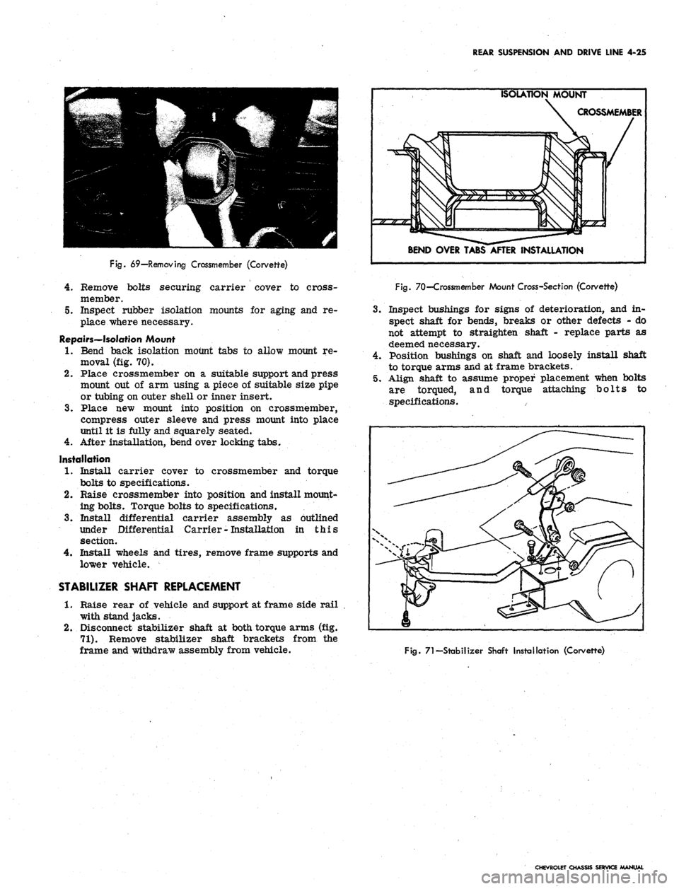
Disconnect stabilizer shaft at both torque arms (fig.
71).
Remove stabilizer shaft brackets from the
frame and withdraw assembly from vehicle.
ISOLATION MOUNT
CROSSMEMBER
BEND OVER TABS AFTER INSTALLATION
Fig.
70—Crossmember Mount Cross-Section (Corvette)
3.
Inspect bushings for signs of deterioration, and in-
spect shaft for bends, breaks or other defects - do
not attempt to straighten shaft - replace parts as
deemed necessary.
4.
Position bushings on shaft and loosely install shaft
to torque arms and at frame brackets.
5.
Align shaft to assume proper placement when bolts
are torqued, and torque attaching bolts to
specifications.
Fig.
71—Stabilizer Shaft Installation (Corvette)
CHEVROLET CHASSIS SERVICE MANUAL
Page 255 of 659

BRAKES 5-22
2.
Replace ail push rods and pull back springs.
3.
Connect hose or line to wheel cylinder.
NOTE:
If replacing front wheel cylinder, con-
nect hose and inspect installation as outlined in
"Hydraulic Brake Hose Replacement".
4.
Install drum and wheel.
5. Bleed brakes as outlined in this section.
ANCHOR PIN
Front Wheel
1.
Raise front of vehicle and place on jack stands.
2.
Remove wheel and drum as outlined in this section.
3.
Remove brake shoe pull back springs, link and guide
plate.
4.
Disengage anchor pin lock and remove anchor pin by
turning counterclockwise.
5. Place new lock plate on anchor pin and pass pin
through the hole in flange plate and screw into tapped
hole in spindle support.
6. Torque pin to 130 lb. ft. and lock by peening over
washer tabs.
7. Install brake shoe guide plate, link and pull back
springs.
8. Adjust brakes, install drum and wheel as outlined
in this section. Test brake operation.
Rear Wheel
Two type anchor pins are used in production for the
rear wheels. The riveted type is not serviced and if
failure or damage should occur to either the anchor
pin or flange plate, both parts will have to be replaced
and the threaded type anchor pin used.
Threaded Type
1.
Raise rear of vehicle and place on jack stands,
2.
Remove wheel and drum as outlined in this section.
3.
Remove brake shoe pull back springs, link and guide
plate.
4.
Remove anchor pin retaining nut and washer and
remove pin from flange plate.
5. Position anchor pin to flange plate, install lock
washer and nut, and torque pin to 80 lb. ft.
6. Install brake shoe guide plate, link and pull back
springs.
7. Adjust brakes and install drum and wheel as outlined
in this section.
8. Test brake operation.
BRAKE DRUMS
Front brake drums are the demountable type; that is,
they can be removed without removing the hub. Rear
brake drums are demountable and may be removed
wihtout removing the axle shaft.
A lanced "knock out" area (fig. 34) is provided in
the web of the brake drum for servicing purposes in
the event retracting of the brake shoes is required in
order to remove the drum.
A small screw driver or hooked wire may be inserted
to disengage the automatic adjuster actuating lever so
the star wheel may be turned.
Removal
1.
Raise vehicle and place on jack stand.
2.
Remove wheel and tire assembly, back off brake
adjustment and remove drum.
Inspection and Reconditioning
Whenever brake drums are removed they should be
thoroughly cleaned and inspected for cracks, scores,
deep grooves, and out-of-round. Any of these conditions
must be corrected since they can impair the efficiency
of brake operation and also can cause premature failure
of other parts.
Smooth up any slight scores by polishing with fine
emery cloth. Heavy or extensive scoring will cause
excessive brake lining wear and it will probably be
necessary to rebore in order to true up the braking
surface.
An out-of-round drum makes accurate brake shoe
adjustment impossible and is likely to cause excessive
wear of other parts of brake mechanism due to its
eccentric action.
A drum that is more than .008" out-of-round on the
diameter is unfit for service and should be rebored.
Out-of^round, as well as taper and wear can be ac-
curately measured with an inside micrometer fitted
with proper extension rods.
If drum is to be rebored for use with standard size
brake facings which are worn very little, only enough
metal should be removed to obtain a true smooth braking
surface.
If drum has to be rebored more than .020" over the
standard diameter, it should be rebored to .060" diameter
oversize and the brake facing should be replaced with
.030"
oversize facings.
A brake drum must not be rebored more than .060"
over the maximum standard diameter, since removal
of more metal will effect, dissipation of heat and may
cause distortion of drum. Chevrolet brake facing is
not furnished larger than .030" oversize and this will
not work efficiently in drums bored more than .060"
oversize.
Brake drums may be refinished either by turning or
grinding. Best brake performance is obtained by turning
drums with a very fine feed. To insure maximum lining
life,
the refinished braking surface must be smooth and
free from chatter or tool marks, and run-out must not
exceed .005" total indicator reading.
Cleaning
New brake drums in parts stock are given a light.
coating of rust proofing oil to prevent the formation of
rust on the critical braking surfaces during the time
that the drums are in storage.
This rust proofing oil must be carefully removed
before the drum is placed in service to prevent any
of this oil from getting on the brake shoe facings, which
might cause an extreme brake grab condition.
It is recommended that a suitable volatile, non-toxic,
greaseless type solvent be used to clean the oil from the
braking surface of the new brake drums before they are
•placed in service to insure the cleanest possible surface.
Gasoline or kerosene should not be used as there is
danger that a portion of the diluated oil substance may
be left on the braking surface that may later cause
difficulty.
Installation
1.
Make brake adjustment as outlined in this section.
CHEVROLET CHASSIS SERVICE MANUAL
Page 481 of 659

SECTION 10
WHEELS AND TIRES
INDEX
Page
General Description
10-1
Maintenance
and
Adjustments
.............. 10—1
Tires
10-1
Pressures . 10-1
Inspection 10-1
Wear 10-1
Rotation 10-4
Noise 10-4
Cleaning 10-4
Change (W/Wheels) 10-4
Wheels 10-5
Static Balancing (w/Tire) 10-5
Page
Dynamic Balancing (w/Tire) . 10-5
Run Out (w/o Tire) 10-5
Cleaning 10-5
Service Operations 10-5
Tires 10-5
Removal 10-5
Installation 10-5
Repair 10^6
Wheels . 10-6
Valve Assembly 10-6
Repair (Rim) 10-7
GENERAL DESCRIPTION
WHEELS
Chevrolet, Chevelle, Camaro, Chevy n, and Corvette
are base equipped with welded steel wheels. Five studs
with nuts fasten each wheel to the front hub or rear axle
flange. Disc brake equipped vehicles (except Chevrolet
and Corvette) require special 14 inch diameter wheels
with a revised design for clearance, Chevrolet disc brake
equipped vehicles have 15 in. diameter wheels as do all
Corvettes.
Chevrolet station wagons, Chevelle Super Sport 396,
Corvette and Camaro Super Sport 350 are base equipped
with 6 in. width wheels. All other vehicles have 5 in.
width wheels, except Chevy n 100, 300 and 500 Series
Sedans, which have 4 in. width wheels.
Do not install 6 inch width wheels or snow chains on
Chevrolets equipped with rear fender skirts.
TIRES
The factory installed tires on Chevrolet passenger
cars are selected to provide the best all around tire
performance for all normal operation. They are de-
signed to operate satisfactorily with loads up to and in-
cluding the specified full rated load capacity of the
automobile when inflated as recommended in the Vehicle
Capacity Rating and Recommended Tire Inflation Pres-
sures Table (see Specifications).
Optional Oversize and 8-Ply Rating Tires
{Chevrolet and Chevelle Only)
Oversize or 8-ply rating tires are not necessary on
passenger cars for normal requirements. However, an
extra margin of tire service is available when these
options are used at loads up to and including full rated
load.
Optional oversize 4-ply rating and/or 8-ply rating
tires are available on models as indicated in the Tire
Usage Chart (see Specifications). On some models (ex-
ample—Station Wagon), space limitations do not permit
the use of a larger size tire; hence, the 8-ply rating
tire is an available option.
In either case, these tires are applicable to extended
operation at or near full rated load or for trailer towing
when an extra margin of tire service is desired. How-
ever, use of a larger tire or an 8-ply rating tire should
not be construed as permitting an increase in the full
rated vehicle load (see Specifications).
MAINTENANCE AND ADJUSTMENTS
TIRES
Inflation Pressures
To ensure the proper tire inflation pressure for the
owners particular requirements follow the recommenda-
tions in the Vehicle Capacity Rating and Recommended
Tire Inflation Pressures Table (seeSpecifications). Keep
tires properly inflated, and check inflation pressures
periodically. This will ensure the best tire life and riding
comfort, over the full range of driving conditions.
Inspection
Every few thousand miles and at each lubrication, tires
should be checked for sharp objects or stones in the
tread. H tire is punctured, it should be repaired using
one of several repair kits available through tire manu-
facturers1 outlets.
Wear
Misalignment
This is wear due to excessive toe-in or toe-out. In
CHEVROLET CHASSIS SERVICE MANUAL