length CHEVROLET CAMARO 1982 Repair Guide
[x] Cancel search | Manufacturer: CHEVROLET, Model Year: 1982, Model line: CAMARO, Model: CHEVROLET CAMARO 1982Pages: 875, PDF Size: 88.64 MB
Page 762 of 875

GM – CAMARO 1982-1992 – Repair Guide (Checked by WxMax) 762
Loctite). If you're worried about getting so
mething together tight enough to hold,
but loose enough to avoid mechanical damage during assembly, one of these
products might offer substantial insurance. Before choosing a threadlocking
compound, read the label on the pa ckage and make sure the product is
compatible with the materials, fluids, etc. involved.
3. Crossthreading. This occu rs when a part such as a bolt is screwed into a
nut or casting at the wrong angle and forced. Cr ossthreading is more
likely to occur if access is diffic ult. It helps to clean and lubricate
fasteners, then to start threading the bolt, spark pl ug, etc. with your
fingers. If you encounter resistance, unscrew the part and start over
again at a different angle until it can be inserted and turned several t\
imes
without much effort. Keep in mind t hat many parts have tapered threads,
so that gentle turning will automatica lly bring the part you're threading to
the proper angle. Don't put a wrench on the part until it's been tightened
a couple of turns by hand. If you s uddenly encounter resistance, and the
part has not seated fully, don't force it. Pull it back out to make sure it's
clean and threading properly.
Be sure to take your time and be pati ent, and always plan ahead. Allow yourself
ample time to perform r epairs and maintenance.
TOOLS AND EQUIPMENT
Without the proper tools and equipment it is impossible to properly service your
vehicle. It would be virtually impossible to catalog every tool that you would
need to perform all of the oper ations in this repair guide. It would be unwise for
the amateur to rush out and buy an expens ive set of tools on the theory that
he/she may need one or more of them at some time.
The best approach is to proceed slowly, gathering a good quality set of those
tools that are used most frequently. Don't be misled by the low cost of bargain
tools. It is far better to spend a little more for better quality. Forged wrenches, 6
or 12-point sockets and fine tooth ratc hets are by far preferable to their less
expensive counterparts. As any good me chanic can tell you, there are few
worse experiences than trying to work on a vehicle with bad tools. Your
monetary savings will be far outweighed by frustration and mangled knuckles.
Begin accumulating those tools that are used most frequently: those associated
with routine maintenance and tune-up. In addition to the normal assortment of
screwdrivers and pliers, you should have the following tools:
• Wrenches/sockets and combination o pen end/box end wrenches in sizes 1/83/4 in. and/or 3mm-19mm 13/16 in. or 5/8 in. spark plug socket
(depending on plug type).
If possible, buy various length socket drive extensions. Universal-joint\
and
wobble extensions can be extremely usef ul, but be careful when using them, as
they can change the amount of torque applied to the socket.
Page 854 of 875

GM – CAMARO 1982-1992 – Repair Guide (Checked by WxMax) 854
IGNITION SWITCH
WARNING
- Before attempting any repairs involving the steering wheel or
disassembly of it, ensure that the Supple mental Inflatable Restraint (Air Bag)
system is properly disarmed.
REPLACEMENT
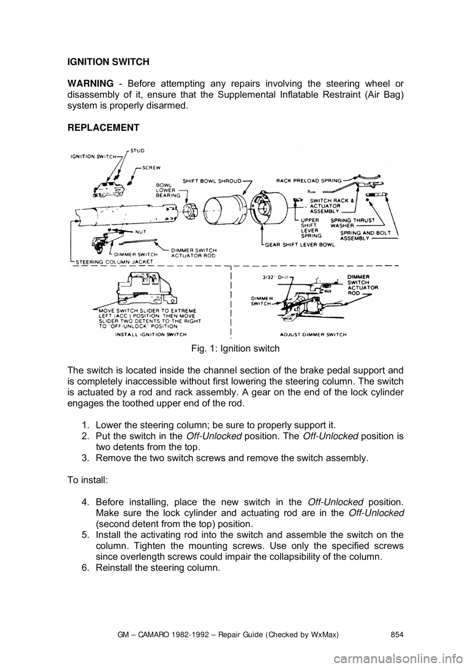
Fig. 1: Ignition switch
The switch is located inside the channe l section of the brake pedal support and
is completely inaccessible without firs t lowering the steering column. The switch
is actuated by a rod and rack assembly . A gear on the end of the lock cylinder
engages the toothed upper end of the rod.
1. Lower the steering column; be sure to properly support it.
2. Put the switch in the Off-Unlocked position. The Off-Unlocked position is
two detents from the top.
3. Remove the two switch screws and remove the switch assembly.
To install: 4. Before installing, place the new switch in the Off-Unlocked position.
Make sure the lock cylinder and actuating rod are in the Off-Unlocked
(second detent from th e top) position.
5. Install the activating rod into the switch and assemble the switch on the
column. Tighten the mount ing screws. Use only the specified screws
since overlength screws could impair the collapsibility of the column.
6. Reinstall the steering column.