length CHEVROLET CAMARO 1982 Repair Guide
[x] Cancel search | Manufacturer: CHEVROLET, Model Year: 1982, Model line: CAMARO, Model: CHEVROLET CAMARO 1982Pages: 875, PDF Size: 88.64 MB
Page 483 of 875
GM – CAMARO 1982-1992 – Repair Guide (Checked by WxMax) 483
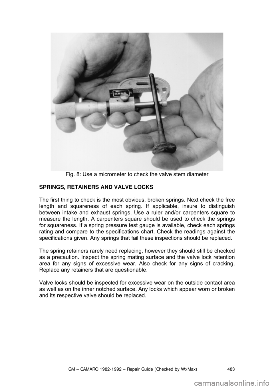
Fig. 8: Use a micrometer to check the valve stem diameter
SPRINGS, RETAINERS AND VALVE LOCKS
The first thing to check is the most obv ious, broken springs. Next check the free
length and squareness of each spring. If applicable, insure to distinguish
between intake and exhaust springs. Use a ruler and/or carpenters square to
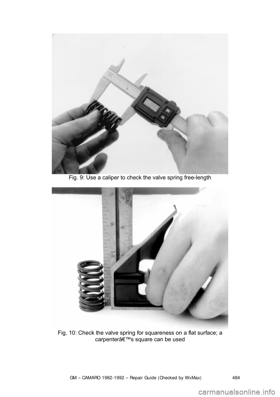
measure the length. A car penters square should be used to check the springs
for squareness. If a spring pressure test gauge is available, check each springs
rating and compare to the specifications chart. Check the readings against the
specifications given. Any springs that fa il these inspections should be replaced.
The spring retainers rarely need replacing, however they should still be checked
as a precaution. Inspect the spring mating surface and the valve lock re\
tention
area for any signs of excessive wear. Also check for any signs of cracking.
Replace any retainers t hat are questionable.
Valve locks should be inspected for exce ssive wear on the outside contact area
as well as on the inner notched surface. Any locks which appear worn or broken
and its respective valve should be replaced.
Page 484 of 875
GM – CAMARO 1982-1992 – Repair Guide (Checked by WxMax) 484
Fig. 9: Use a caliper to che ck the valve spring free-length
Fig. 10: Check the valve spring for squareness on a flat surface; a
carpenter’s square can be used
Page 487 of 875
GM – CAMARO 1982-1992 – Repair Guide (Checked by WxMax) 487
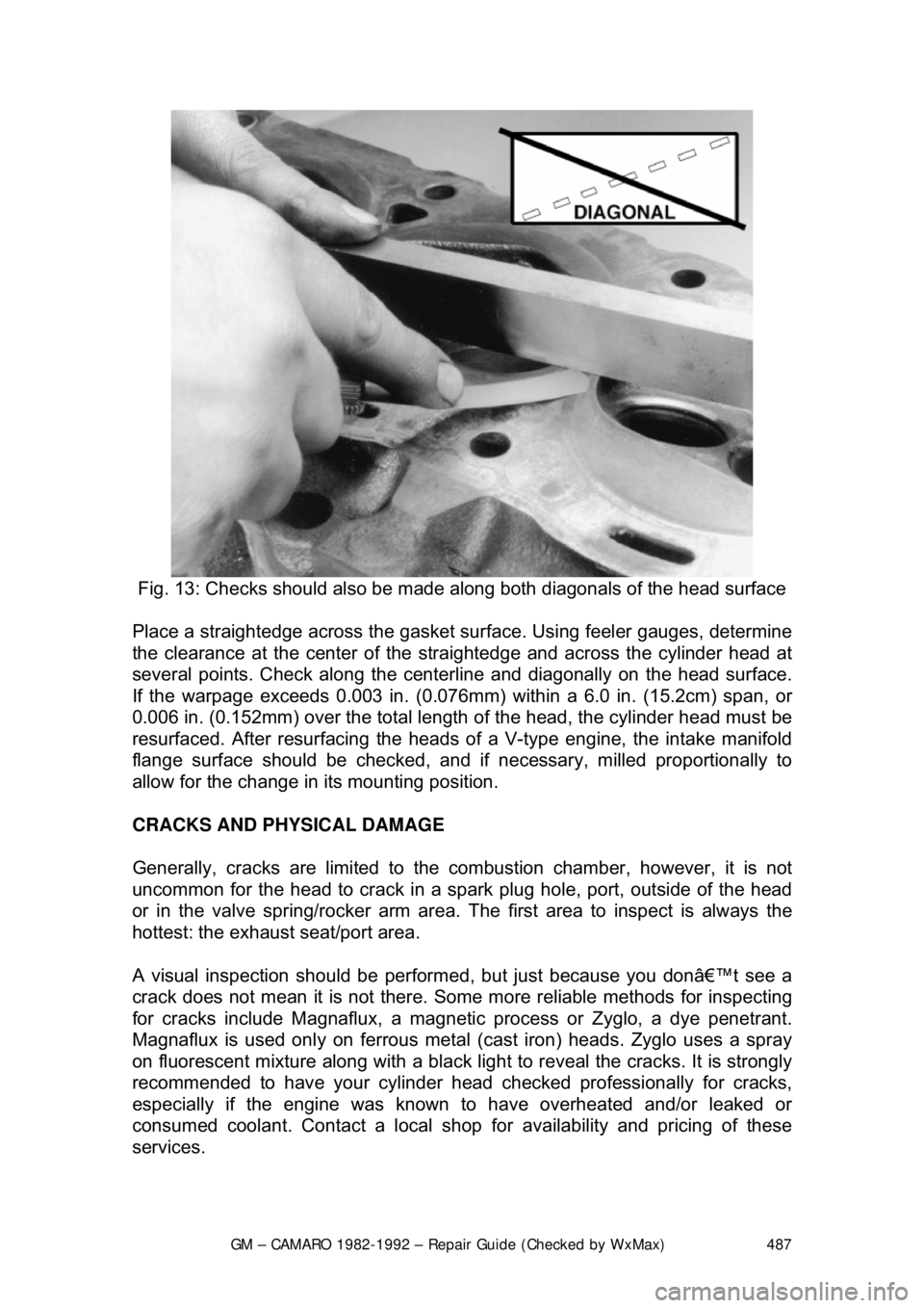
Fig. 13: Checks should also be made al ong both diagonals of the head surface
Place a straightedge across the gasket surf ace. Using feeler gauges, determine
the clearance at the cent er of the straightedge and across the cylinder head at
several points. Check along the centerli ne and diagonally on the head surface.
If the warpage exceeds 0.003 in. (0.076mm) within a 6.0 in. (15.2cm) span, or
0.006 in. (0.152mm) over the total length of the head, the cylinder head must be
resurfaced. After resurfacing the heads of a V-type engine, the intake manifold
flange surface should be checked, and if necessary, milled proportionally to
allow for the change in its mounting position.
CRACKS AND PHYSICAL DAMAGE
Generally, cracks are limited to the comb ustion chamber, however, it is not
uncommon for the head to crack in a s park plug hole, port, outside of the head
or in the valve spring/rocker arm area. The first area to inspect is always the
hottest: the exhaust seat/port area.
A visual inspection should be perform ed, but just because you don’t see a
crack does not mean it is not there. Some more reliable methods for inspecting
for cracks include Magnaflux, a magnetic process or Zyglo, a dye penetrant.
Magnaflux is used onl y on ferrous metal (cast iron) heads. Zyglo uses a spray
on fluorescent mixture along with a black light to reveal the cracks. It is strongly
recommended to have your cylinder head c hecked professionally for cracks,
especially if the engine was known to have overheated and/or leaked or
consumed coolant. Contact a local shop fo r availability and pricing of these
services.
Page 490 of 875

GM – CAMARO 1982-1992 – Repair Guide (Checked by WxMax) 490
To replace cast-in type valve guides, t
hey must be drilled out, then reamed to
accept replacement guides. This must be done on a fixture which will allow
centering and leveling off of the original valve seat or guide, otherwise a serious
guide-to-seat misalignment may occur maki ng it impossible to properly machine
the seat.
Replaceable-type guides are pressed into the cylinder head. A hammer and a
stepped drift or punch may be used to inst all and remove the guides. Before
removing the guides, measure the protrusi on on the spring side of the head and
record it for installation. Use the stepped drift to hammer out the old guide from
the combustion chamber side of the head. When installing, determine whether
or not the guide also seal s a water jacket in the head, and if it does, use the
recommended sealing agent. If there is no water jacket, grease the valve guide
and its bore. Use the stepped drift, and hamme r the new guide into the cylinder
head from the spring side of the cylinder head. A stack of washers the same
thickness as the measured protrusion may help the installation process.
VALVE SEATS
Before any valve seat machining can be performed, the guides must be within
factory recommended specifications.
If any machining or replacements were made to the valve guides, the seats
must be machined.
If the seats are in good condition, the va lves can be lapped to the seats, and the
cylinder head assembled. See the valves in formation for instructions on lapping.
If the valve seats are worn, cracked or damaged, they must be serviced by a
machine shop. The valve seat must be per fectly centered to the valve guide,
which requires very accurate machining.
CYLINDER HEAD SURFACE
If the cylinder head is war ped, it must be machined flat. If the warpage is
extremely severe, the head may need to be replaced. In some instances, it may
be possible to straighten a warped head enough to allow machining. In either
case, contact a professional machine shop for service.
CRACKS AND PHYSICAL DAMAGE
Certain cracks can be repaired in both ca st iron and aluminum heads. For cast
iron, a tapered threaded insert is inst alled along the length of the crack.
Aluminum can also use the tapered inse rts, however welding is the preferred
method. Some physical damage can be repaired through brazing or welding.
Contact a machine shop to get expert advice for your particular dilemma.
ASSEMBLY
Page 495 of 875

GM – CAMARO 1982-1992 – Repair Guide (Checked by WxMax) 495
Again, rotate the engine, this time
to position the number one cylinder bore
(head surface) up. Turn the crankshaft until the number one piston is at the
bottom of its travel, this should allow t he maximum access to its connecting rod.
Remove the number one co nnecting rods fasteners and cap and place two
lengths of rubber hose over the rod bolts/studs to protect the crankshaft from
damage. Using a sturdy wooden dowel and a hammer, push the connecting rod
up about 1 in. (25mm) from the cranks haft and remove the upper bearing insert.
Continue pushing or tapping the connecti ng rod up until the piston rings are out
of the cylinder bore. Remove the piston and rod by hand, put the upper half of
the bearing insert back into the rod, in stall the cap with its bearing insert
installed, and hand-tighten the cap fasteners. If the parts are kept in order in this
manner, they will not get lost and you wil l be able to tell which bearings came
form what cylinder if any problems are discovered and diagnosis is necessary.
Remove all the other piston assemblie s in the same manner. On V-style
engines, remove all of the pistons from one bank, then reposition the engine
with the other cylinder bank head surface up, and remo ve that banks piston
assemblies.
The only remaining component in the engine block should now be the
crankshaft. Loosen the main bearing ca ps evenly until the fasteners can be
turned by hand, then remove them and the caps. Remove the crankshaft fro\
m
the engine block. Thoroughly clea n all of the components.
INSPECTION
Now that the engine block and all of its components ar e clean, it's time to
inspect them for wear and/or damage. To accurately inspect them, you will need
some specialized tools:
• Two or three separate micromet ers to measure the pistons and
crankshaft journals
• A dial indicator
• Telescoping gauges for the cylinder bores
• A rod alignment fixture to check for bent connecting rods
If you do not have access to the proper tools, you may want to bring the
components to a shop that does.
Generally, you shouldn't expect cracks in the engine block or its components
unless it was known to leak, consume or mix engine fluids, it was severely
overheated, or there was ev idence of bad bearings and/or crankshaft damage.
A visual inspection should be performed on all of the components, but just
because you don't see a crack does not mean it is not there. Some more
reliable methods for inspecting for cracks include Magnaflux, a magnetic
process or Zyglo, a dye penetrant. M agnaflux is used only on ferrous metal
(cast iron). Zyglo uses a spray on fluoresce nt mixture along with a black light to
reveal the cracks. It is strongly recommended to have your engine block
checked professionally for cracks, especia lly if the engine was known to have
overheated and/or leaked or consumed coolant. Contact a local shop for
availability and pricing of these services.
Page 496 of 875

GM – CAMARO 1982-1992 – Repair Guide (Checked by WxMax) 496
ENGINE BLOCK
ENGINE BLOCK BEARING ALIGNMENT
Remove the main bearing caps and, if sti
ll installed, the main bearing inserts.
Inspect all of the main bearing saddles and caps for damage, burrs or high
spots. If damage is found, and it is caused from a spun main bearing, the block
will need to be align-bored or, if severe enough, replacement. Any burrs or high
spots should be carefully removed with a metal file.
Place a straightedge on the bearing saddles, in the engine block, along the
centerline of the crankshaft. If any cl earance exists between the straightedge
and the saddles, the block must be align-bored.
Align-boring consists of machining th e main bearing saddles and caps by
means of a flycutter that runs through the bearing saddles.
DECK FLATNESS
The top of the engine blo ck where the cylinder head m ounts is called the deck.
Insure that the deck surface is clean of dirt, carbon deposits and old gasket
material. Place a straightedge across the surface of the deck along its
centerline and, using feeler gauges, check the clearance along several points.
Repeat the checking procedure with th e straightedge placed along both
diagonals of the deck surface. If the reading exceeds 0.003 in. (0.076mm)
within a 6.0 in. (15.2cm) span, or 0.006 in . (0.152mm) over the total length of
the deck, it must be machined.
CYLINDER BORES
The cylinder bores house the pistons and are slightly larger than the pistons
themselves. A common piston-to-bor e clearance is 0.0015-0.0025 in.
(0.0381mm-0.0635mm). Inspect and measur e the cylinder bores. The bore
should be checked for out-of-roundness, t aper and size. The results of this
inspection will determine w hether the cylinder can be us ed in its existing size
and condition, or a rebore to the next oversize is required (or in the case of
removable sleeves, have replacements installed).
Page 634 of 875
GM – CAMARO 1982-1992 – Repair Guide (Checked by WxMax) 634
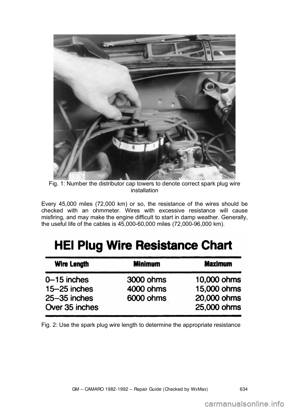
Fig. 1: Number the distributor cap to wers to denote correct spark plug wire
installation
Every 45,000 miles (72,000 km) or so, th e resistance of the wires should be
checked with an ohmmeter. Wires wit h excessive resistance will cause
misfiring, and may make the engine difficult to start in damp weather. Generally,
the useful life of the cables is 45,000-60,000 miles (72,000-96,000 km).
Fig. 2: Use the spark plug wire length to determine the appropriate resistance
Page 637 of 875
GM – CAMARO 1982-1992 – Repair Guide (Checked by WxMax) 637
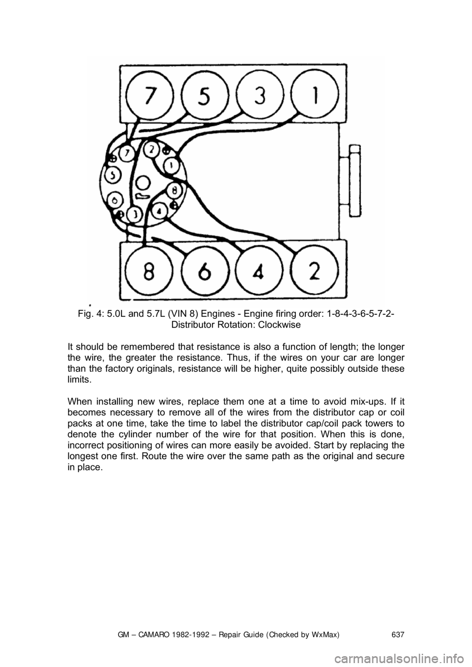
Fig. 4: 5.0L and 5.7L (VIN 8) Engines - Engine firing order: 1-8-4-3-6-5-7-2-
Distributor Rotation: Clockwise
It should be remembered that resistance is also a function of length; the longer
the wire, the greater the re sistance. Thus, if the wires on your car are longer
than the factory originals, resistance will be higher, qui te possibly outside these
limits.
When installing new wires, r eplace them one at a time to avoid mix-ups. If it
becomes necessary to remove all of the wires from the distributor cap or coil
packs at one time, take the time to label the distributor cap/coil pack towers to
denote the cylinder number of the wire fo r that position. When this is done,
incorrect positioning of wires can more eas ily be avoided. Start by replacing the
longest one first. Route the wire over the same path as the original and secure
in place.
Page 735 of 875
GM – CAMARO 1982-1992 – Repair Guide (Checked by WxMax) 735
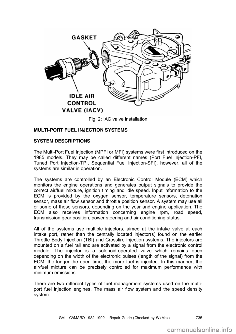
Fig. 2: IAC valve installation
MULTI-PORT FUEL INJECTION SYSTEMS
SYSTEM DESCRIPTIONS
The Multi-Port Fuel Injection (MPFI or MFI) systems were first introduced on the
1985 models. They may be called different names (Port Fuel Injection-PFI,
Tuned Port Injection-TPI, Sequential Fuel Injection-SFI), however, all of the
systems are similar in operation.
The systems are controlled by an Elec tronic Control Module (ECM) which
monitors the engine operations and gen erates output signals to provide the
correct air/fuel mixture, ignition timing and idle speed. Input information to the
ECM is provided by the oxygen sens or, temperature sensors, detonation
sensor, mass air flow sensor and throttle position sensor. A system may use all
or some of these sensors, depending on the year and engine application. The
ECM also receives information concerning engine rpm, road speed,
transmission gear position, power steer ing and air conditioning status.
All of the systems use multiple injector s, aimed at the intake valve at each
intake port, rather than the centrally lo cated injector(s) found on the earlier
Throttle Body Injection (TBI) and Crossfir e Injection systems. The injectors are
mounted on a fuel rail and ar e activated by a signal from the electronic control
module. The injector is a solenoi d-operated valve which remains open
depending on the width of t he electronic pulses (length of the signal) from the
ECM; the longer the open time, the more f uel is injected. In this manner, the
air/fuel mixture can be precisely c ontrolled for maximum performance with
minimum emissions.
There are two different types of f uel management systems used on the multi-
port fuel injection engines. The mass air flow system and the speed density
system.
Page 743 of 875

GM – CAMARO 1982-1992 – Repair Guide (Checked by WxMax) 743
MINIMUM IDLE SPEED
The minimum idle speed should onl
y be adjusted under two conditions:
If the throttle body has been replaced.
After every other possible cause for the in correct idle speed has been explored.
There are many possible causes for incorre ct idle speed, most of which require
a high level of diagnostic skill as well as expensive testing equipment. Check
the vehicle for vacuum leaks, incorrect valve or ignition timing, deposit
accumulation in the throttle bore or valve, sticking throttle linkage or bent throttle
valves. If the vehicle will still not idle pr operly after checking these areas, it
should be diagnosed by a professional.
1. Pierce the idle stop screw with an awl. Apply leverage to remove it.
2. Make sure the IAC valve is connect ed. Short the A and B terminals of the
ALDL connector together with a length of wire.
3. Turn the ignition to the ON positi on, but do not start the engine. Wait at
least 30 seconds before proceeding.
4. With the ignition ON, disconnect the IAC valve connector.
5. Separate the set-timing connector. Th is eliminates the possibility of
changes in engine speed due to variations of engine timing.
6. Start the engine and remove t he wire shorting the A and B terminals
together. It may be necessary to hold the throttle open slightly to prevent
the engine from stalling.
7. Allow the engine to reach no rmal operating temperature.
8. Adjust the idle speed to the following: a. 2.8L Engines - 450-550 rp m A/T or 550-650 rpm M/T
b. 3.1L Engines - Refer to the underhood emissions sticker
c. 5.0L and 5.7L TPI engines - 400-450 rpm.
If these figures differ from t hose on the underhood emissions
sticker, always follow the specifications on the emissions sticker.
9. Turn the ignition OFF and connect the IAC valve harness. On models up
to 1989, adjust the Throttle Position Sensor.
THROTTLE POSITION SENSOR (TPS) 1. Install three jumper wires betw een the TPS and the harness connector.
2. Use a digital voltmeter connected to terminals A and B of the TPS.
3. Turn the ignition switch ON , but do not start the engine.
4. Loosen the TPS attaching screws and adj ust the sensor to the following:
a. 2.8L Engines - 0.50-0.60 volts
b. 5.0L and 5.7L TPI Engines - 0.47-0.61 volts
5. Tighten the attaching screws, then check that the reading has not been
disturbed.
6. With the ignition OFF, remove the jumper wires. Reconnect the TPS
harness.