alarm CHEVROLET CAMARO 1982 Repair Guide
[x] Cancel search | Manufacturer: CHEVROLET, Model Year: 1982, Model line: CAMARO, Model: CHEVROLET CAMARO 1982Pages: 875, PDF Size: 88.64 MB
Page 323 of 875

GM – CAMARO 1982-1992 – Repair Guide (Checked by WxMax) 323
Replacement kits include new bearing
cups and conventional snaprings to
replace the original nylon rings. These replacement rings must go inboard of the
yoke in contrast to outboard mounting of the Dana and Cleveland designs.
Previous service to the Saginaw U-joints can be recognized by the presence of
snaprings inboard of the yoke.
Bad U-joints, requiring replacement, will produce a clunking sound when the car
is put into gear. This is due to worn needle bearings or a scored trunnion end
possibly caused by improper lubricati on during assembly. Camaro U-joints
require no periodic maintenance and theref ore have no lubrication fittings.
DRIVESHAFT
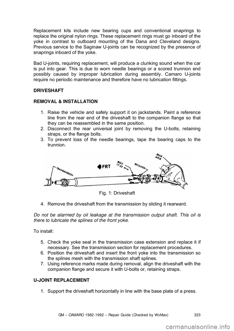
REMOVAL & INSTALLATION 1. Raise the vehicle and safely su pport it on jackstands. Paint a reference
line from the rear end of the drives haft to the companion flange so that
they can be reassembled in the same position.
2. Disconnect the rear universal join t by removing the U-bolts, retaining
straps, or the flange bolts.
3. To prevent loss of the needle bear ings, tape the bearing caps to the
trunnion.
Fig. 1: Driveshaft
4. Remove the driveshaft from the tr ansmission by sliding it rearward.
Do not be alarmed by oil l eakage at the transmission output shaft. This oil is
there to lubricate the sp lines of the front yoke.
To install: 5. Check the yoke seal in the transmi ssion case extension and replace it if
necessary. See the transmission sect ion for replacement procedures.
6. Position the driveshaft and insert t he front yoke into the transmission so
the splines mesh with the transmission shaft splines.
7. Using reference marks made during re moval, align the driveshaft with the
companion flange and secure it with U-bolts or, retaining straps.
U-JOINT REPLACEMENT 1. Support the driveshaft horizontally in line with the base plate of a press.
Page 467 of 875

GM – CAMARO 1982-1992 – Repair Guide (Checked by WxMax) 467
8. According to the tool manufacture
r's instructions, connect a remote
starting switch to the starting circuit.
9. With the ignition switch in the OFF position, use the remote starting
switch to crank the engine through at least five compression strokes
(approximately 5 seconds of cranking) and record the highest reading on
the gauge.
10. Repeat the test on each cylinder, cranking the engine approximately the
same number of compression stroke s and/or time as the first.
11. Compare the highest readi ngs from each cylinder to that of the others.
The indicated compression pre ssures are considered within
specifications if the lo west reading cylinder is within 75 percent of the
pressure recorded for the highest readi ng cylinder. For example, if your
highest reading cylinder pressure was 150 psi (1034 kPa), then 75
percent of that would be 113 psi (779 kPa). So the lowest reading
cylinder should be no less than 113 psi (779 kPa).
12. If a cylinder exhibits an unusually low compression reading, pour a
tablespoon of clean engine oil into the cylinder through the spark plug
hole and repeat the compression tes t. If the compression rises after
adding oil, it means that the cylinder's piston rings and/or cylinder bore
are damaged or worn. If the pressure re mains low, the valves may not be
seating properly (a valve job is needed), or the head gasket may be
blown near that cylinder. If compressi on in any two adjacent cylinders is
low, and if the addition of oil doesn' t help raise compression, there is
leakage past the head gasket. Oil and coolant in the combustion
chamber, combined with blue or const ant white smoke from the tail pipe,
are symptoms of this pr oblem. However, don't be alarmed by the normal
white smoke emitted from the tail pipe during engine warm-up or from
cold weather driving. There may be evidence of water droplets on the
engine dipstick and/or oil droplets in the cooling system if a head gasket
is blown.
OIL PRESSURE TEST
Check for proper oil pressu re at the sending unit passage with an externally
mounted mechanical oil pressure gauge (a s opposed to relying on a factory
installed dash-mounted gauge). A tachom eter may also be needed, as some
specifications may require running the engine at a specific rpm.
1. With the engine cold, locate and remo ve the oil pressure sending unit.
2. Following the manufacturer's inst ructions, connect a mechanical oil
pressure gauge and, if necessary, a tachometer to the engine.
3. Start the engine and allow it to idle.
4. Check the oil pressure reading when cold and record the number. You
may need to run the engine at a specified rpm, so check the
specifications chart located earlier in this section.
5. Run the engine until normal operati ng temperature is reached (upper
radiator hose will feel warm).
6. Check the oil pressure reading agai n with the engine hot and record the
number. Turn the engine OFF.