belt CHEVROLET CAMARO 1982 Repair Guide
[x] Cancel search | Manufacturer: CHEVROLET, Model Year: 1982, Model line: CAMARO, Model: CHEVROLET CAMARO 1982Pages: 875, PDF Size: 88.64 MB
Page 28 of 875
GM – CAMARO 1982-1992 – Repair Guide (Checked by WxMax) 28
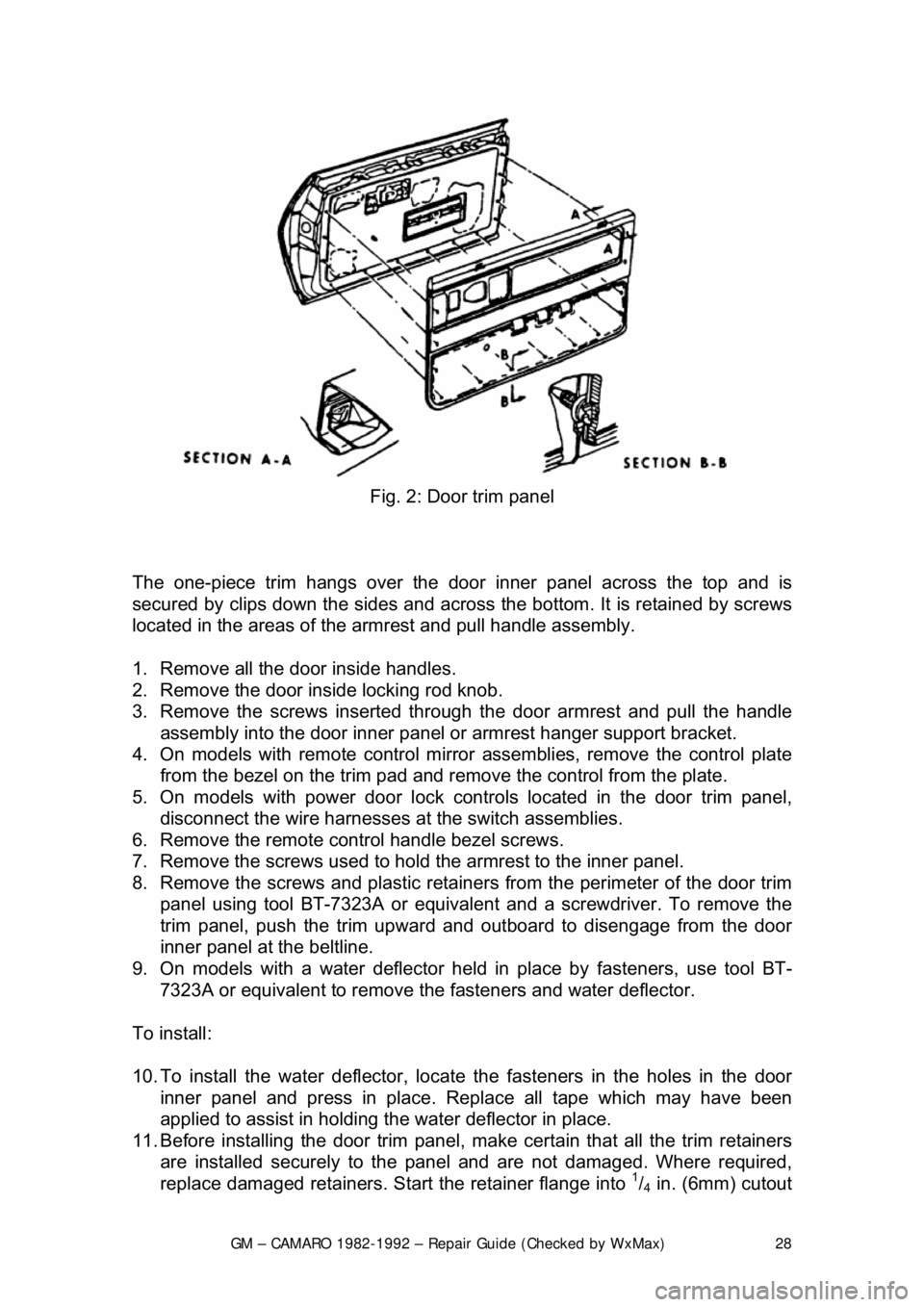
Fig. 2: Door trim panel
The one-piece trim hangs over the door inner panel across the top and is
secured by clips down the sides and across the bottom. It is retained by screws
located in the areas of the armrest and pull handle assembly.
1. Remove all the door inside handles.
2. Remove the door inside locking rod knob.
3. Remove the screws inserted through the door armrest and pull the handle
assembly into the door inner panel or armrest hanger support bracket.
4. On models with remote control mirror assemblies, remove the control plate
from the bezel on the trim pad and remo ve the control from the plate.
5. On models with power door lock contro ls located in the door trim panel,
disconnect the wire harnesses at the switch assemblies.
6. Remove the remote control handle bezel screws.
7. Remove the screws used to hold the armrest to the inner panel.
8. Remove the screws and plastic retainer s from the perimeter of the door trim
panel using tool BT-7323A or equivalent and a screwdriver. To remove the
trim panel, push the trim upward and out board to disengage from the door
inner panel at the beltline.
9. On models with a water deflector held in place by fasteners, use tool BT-
7323A or equivalent to remove th e fasteners and water deflector.
To install:
10. To install the water deflector, locate the fasteners in the holes in the door
inner panel and press in place. R eplace all tape which may have been
applied to assist in holding t he water deflector in place.
11. Before installing the door trim panel, make certain that all the trim retainers
are installed securely to the panel and are not damaged. Where required,
replace damaged retainers. St art the retainer flange into
1/4 in. (6mm) cutout
Page 42 of 875
GM – CAMARO 1982-1992 – Repair Guide (Checked by WxMax) 42
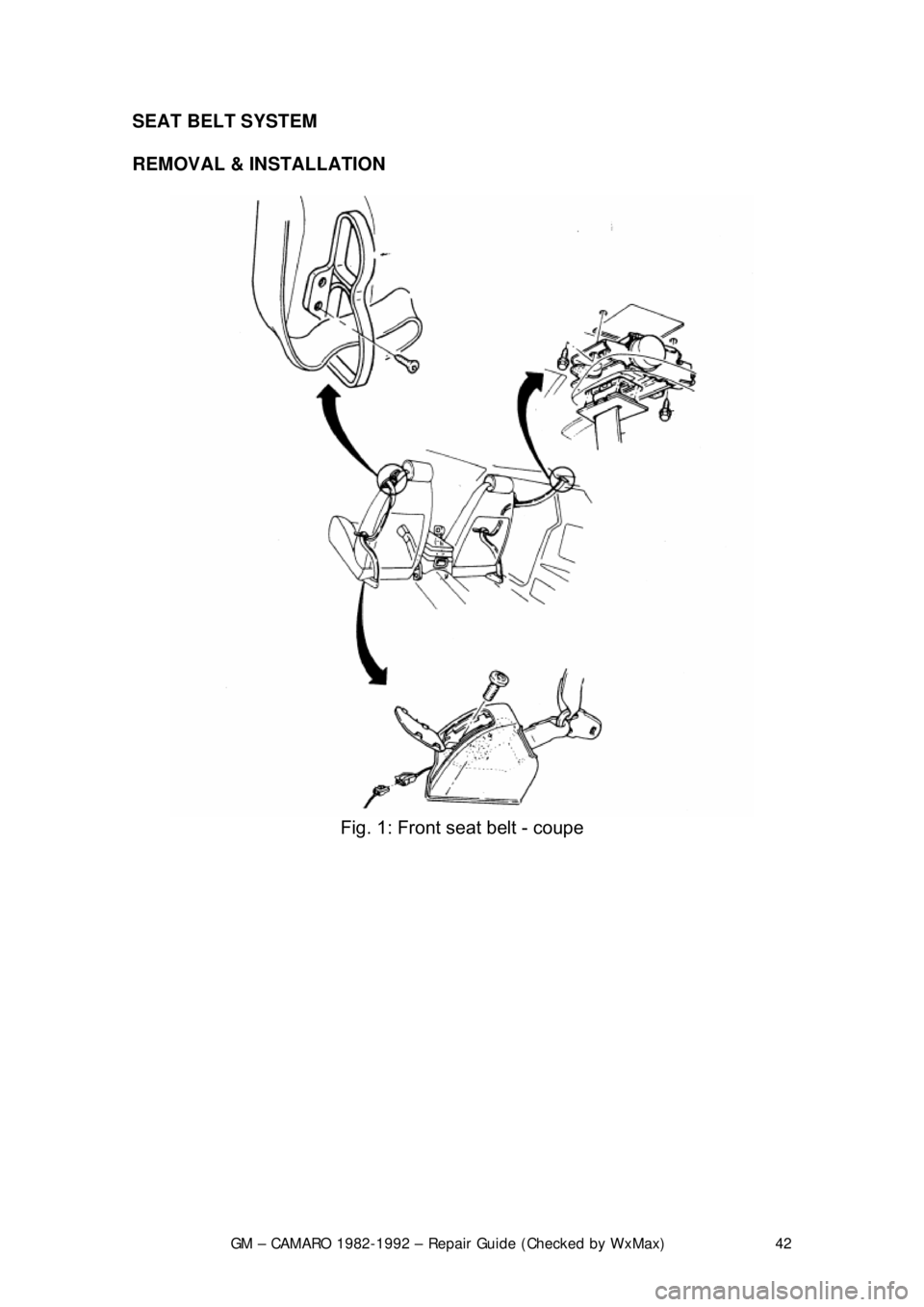
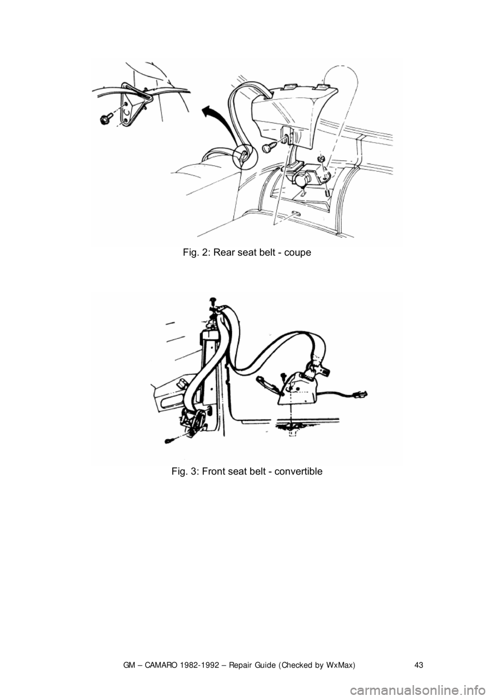
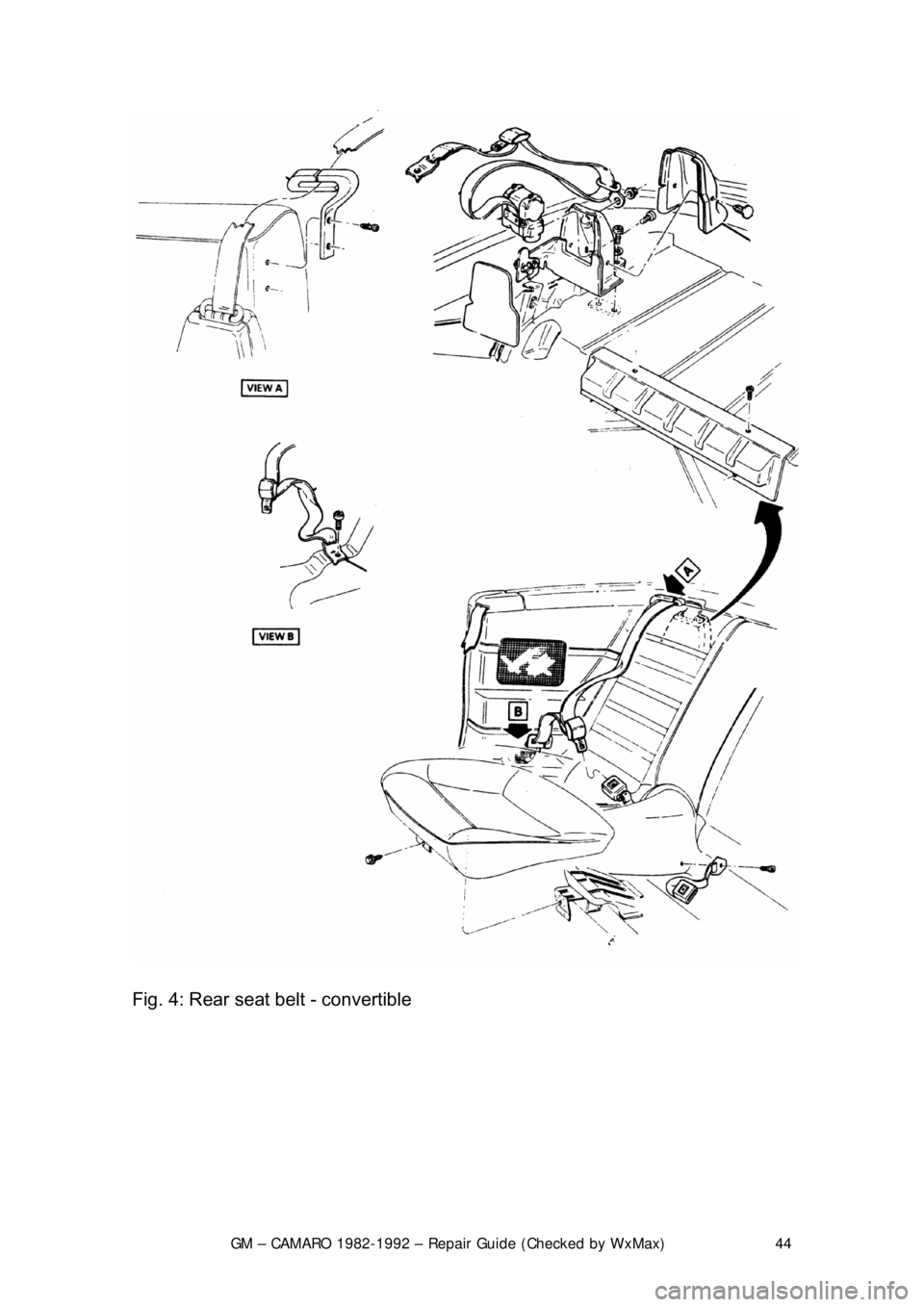
SEAT BELT SYSTEM
REMOVAL & INSTALLATION
Fig. 1: Front seat belt - coupe
Page 43 of 875
GM – CAMARO 1982-1992 – Repair Guide (Checked by WxMax) 43
Fig. 2: Rear seat belt - coupe
Fig. 3: Front seat belt - convertible
Page 44 of 875
GM – CAMARO 1982-1992 – Repair Guide (Checked by WxMax) 44
Fig. 4: Rear seat belt - convertible
Page 45 of 875
GM – CAMARO 1982-1992 – Repair Guide (Checked by WxMax) 45
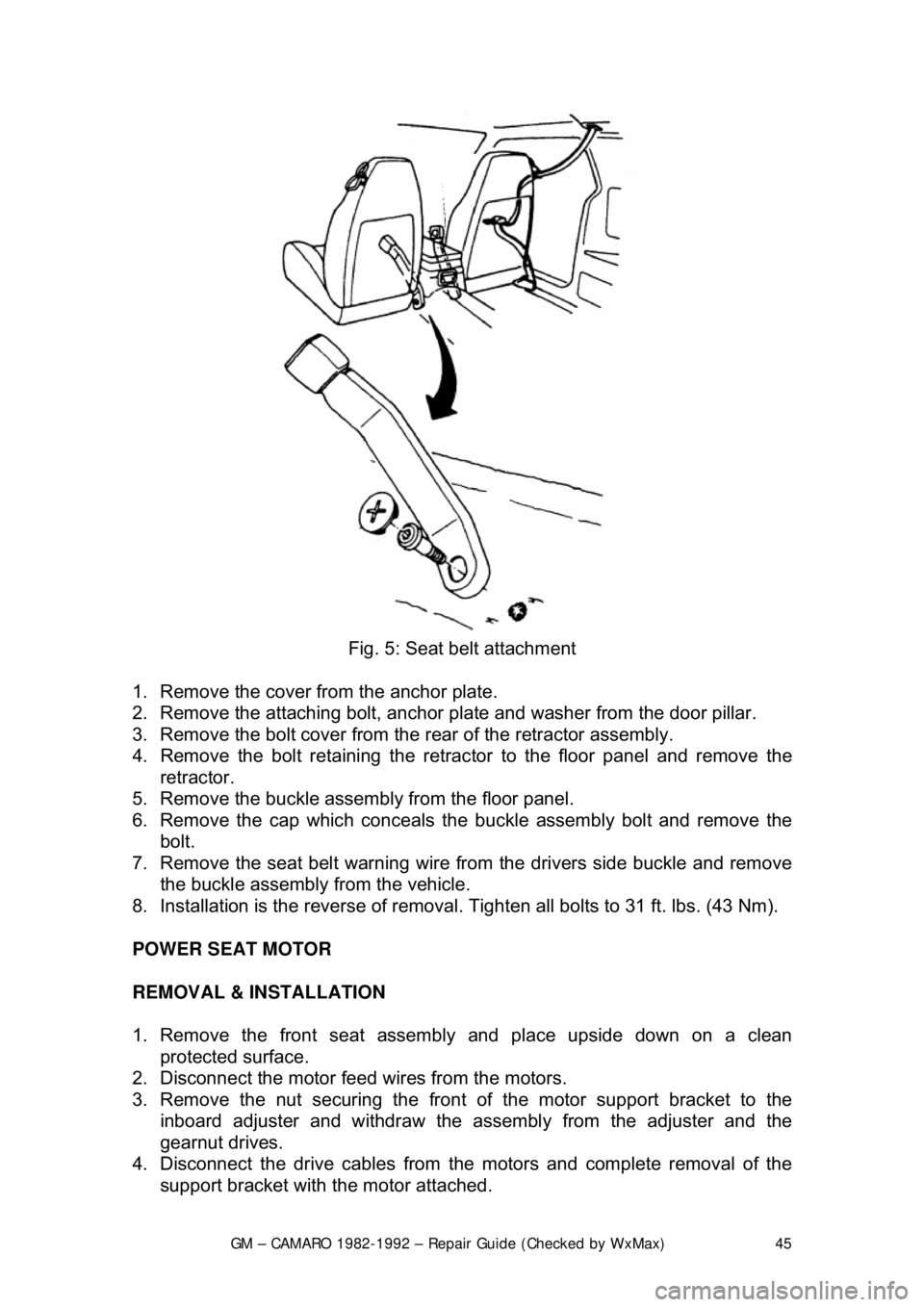
Fig. 5: Seat belt attachment
1. Remove the cover from the anchor plate.
2. Remove the attaching bolt, anchor pl ate and washer from the door pillar.
3. Remove the bolt cover from the rear of the retractor assembly.
4. Remove the bolt retaining the retrac tor to the floor panel and remove the
retractor.
5. Remove the buckle assemb ly from the floor panel.
6. Remove the cap which conceals t he buckle assembly bolt and remove the
bolt.
7. Remove the seat belt warning wire from the drivers side buckle and remove
the buckle assembly from the vehicle.
8. Installation is the reverse of removal. Tighten all bolts to 31 ft. lbs. (43 Nm).
POWER SEAT MOTOR
REMOVAL & INSTALLATION
1. Remove the front seat assemb ly and place upside down on a clean
protected surface.
2. Disconnect the motor feed wires from the motors.
3. Remove the nut securing the front of the motor support bracket to the
inboard adjuster and withdraw the asse mbly from the adjuster and the
gearnut drives.
4. Disconnect the drive cables from t he motors and complete removal of the
support bracket with the motor attached.
Page 146 of 875
GM – CAMARO 1982-1992 – Repair Guide (Checked by WxMax) 146
SUPPLEMENTAL INFLATABLE RESTRAINT SYSTEM
GENERAL INFORMATION
All 1990-1992 models are equi
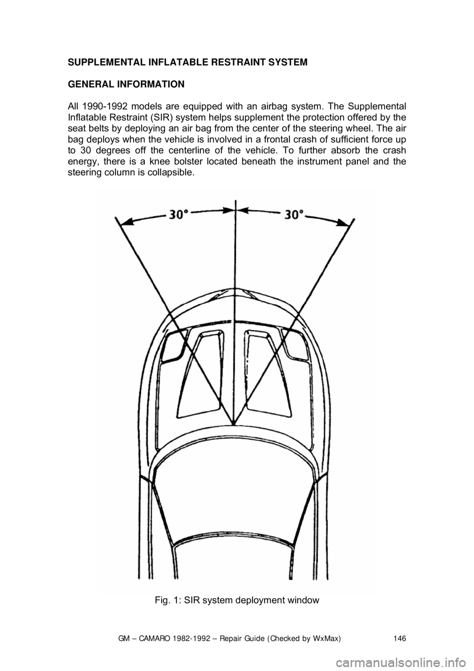
pped with an airbag system. The Supplemental
Inflatable Restraint (SIR) syst em helps supplement the protection offered by the
seat belts by deploying an ai r bag from the center of the steering wheel. The air
bag deploys when the vehicle is involved in a frontal crash of sufficient force up
to 30 degrees off the center line of the vehicle. To further absorb the crash
energy, there is a knee bolster located beneath the instrument panel and the
steering column is collapsible.
Fig. 1: SIR system deployment window
Page 351 of 875

GM – CAMARO 1982-1992 – Repair Guide (Checked by WxMax) 351
alternating current developed
within the stator windings to a direct (DC) current
at the output (BAT) terminal. Three of these diodes are negative and are
mounted flush with the end frame while t he other three are positive and are
mounted into a strip called a heat sink. The positive diodes are easily identified
as the ones within small cavities or depressions.
The alternator charging system is a negative (-) ground system which consists
of an alternator, a regulat or, a charge indicator, a storage battery and wiring
connecting the components, and fuse link wire.
The alternator is belt-driven from t he engine. Energy is supplied from the
alternator/regulator system to the rotati ng field through two brushes to two slip-
rings. The slip-rings are mounted on the rotor shaft and are connected t\
o the
field coil. This energy supplied to the ro tating field from the battery is called
excitation current and is used to init ially energize the field to begin the
generation of electricity. Once the alter nator starts to generate electricity, the
excitation current comes from its ow n output rather than the battery.
The alternator produces power in the form of alternating current. The alternating
current is rectified by 6 diodes into dire ct current. The direct current is used to
charge the battery and power the rest of the electrical system.
When the ignition key is turned ON, current flows from the battery, through the
charging system indicator light on the in strument panel, to the voltage regulator,
and to the alternator. Since the alternat or is not producing any current, the
alternator warning light comes on. When the engine is started, the alternator
begins to produce current and turns the alte rnator light off. As the alternator
turns and produces current, the current is divided in two ways: part to the
battery(to charge the battery and power the electrical components of the
vehicle), and part is returned to the alte rnator (to enable it to increase its
output). In this situation, the alternator is receiving current from the battery and
from itself. A voltage regulat or is wired into the current supply to the alternator
to prevent it from receiving too much cu rrent which would cause it to put out too
much current. Conversely, if the voltage regulator does not allow the alternator
to receive enough current, the battery will not be fully charged and will
eventually go dead.
The battery is connected to the alternator at all times, whether the ignition key is
turned ON or not. If the battery were shorted to ground, the alternator would
also be shorted. This woul d damage the alternator. To prevent this, a fuse link
is installed in the wiring between the battery and the alternator. If the battery is
shorted, the fuse link melts, protecting the alternator.
An alternator is better that a convent ional, DC shunt generator because it is
lighter and more compact, because it is designed to supply the battery and
accessory circuits through a wide range of engine speeds, and because it
eliminates the necessary maintenance of replacing brushes and servicing
commutators.
PRECAUTIONS
Page 352 of 875

GM – CAMARO 1982-1992 – Repair Guide (Checked by WxMax) 352
To prevent serious damage to the alte
rnator and the rest of the charging
system, the following precauti ons must be observed:
• Never reverse the battery connections.
• Booster batteries for starting must be connected properly: positive-to-
positive and negative-to-ground.
• Disconnect the battery cables before using a fast charger; the charger
has a tendency to force current through the diodes in the opposite
direction for which they were designed. This burns out the diodes.
• Never use a fast charger as a booster for starting the vehicle.
• Never disconnect the voltage regulator while the engine is running.
• Avoid long soldering times when replacing diodes or transistors.
Prolonged heat is damaging to AC alternators.
• Do not use test lamps of more t han 12 volts (V) for checking diode
continuity.
• Do not short across or ground any of the terminals on the AC alternator.
• The polarity of the battery, alter nator, and regulator must be matched
and considered before making any elec trical connections within the
system.
• Never operate the alternator on an open circuit. make sure that all
connections within the circ uit are clean and tight.
• Disconnect the battery terminals when performing any service on the
electrical system. This wil l eliminate the possibility of accidental reversal
of polarity.
• Disconnect the battery ground cable if arc welding is to be done on any
part of the car.
CHARGING SYSTEM TROUBLESHOOTING
There are many possible ways in whic h the charging system can malfunction.
Often the source of a problem is diffi cult to diagnose, requiring special
equipment and a good deal of experience. However, when the charging system
fails completely and causes the dash boar d warning light to come on or the
battery to become dead the following items may be checked:
1. The battery is known to be good and fully charged.
2. The alternator belt is in good condition and adjusted to the proper
tension.
3. All connections in t he system are clean and tight.
REMOVAL & INSTALLATION
Page 354 of 875
GM – CAMARO 1982-1992 – Repair Guide (Checked by WxMax) 354
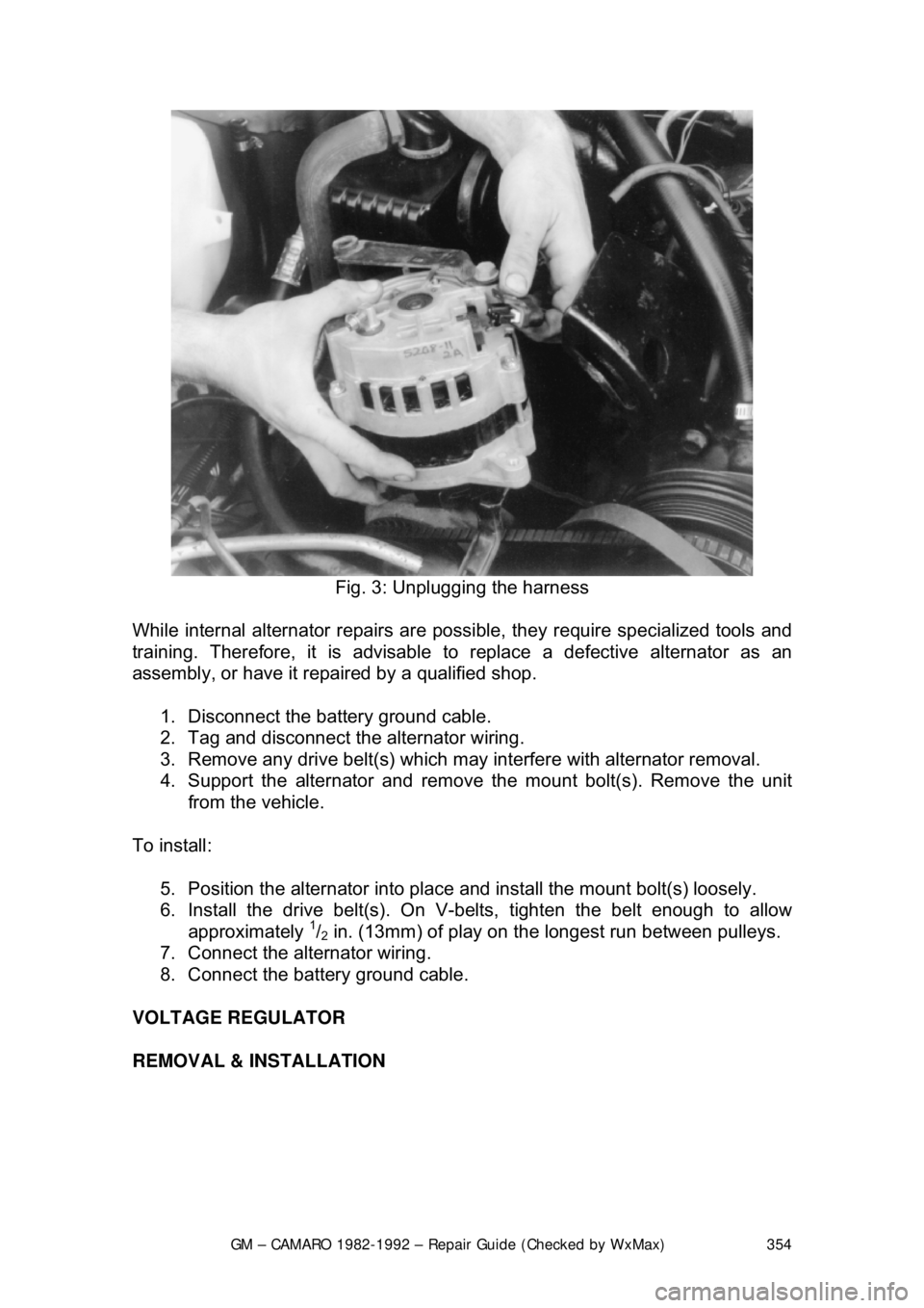
Fig. 3: Unplugging the harness
While internal alternator repairs are possi ble, they require specialized tools and
training. Therefore, it is advisable to replace a defective alternator as an
assembly, or have it repai red by a qualified shop.
1. Disconnect the battery ground cable.
2. Tag and disconnect the alternator wiring.
3. Remove any drive belt(s) which may interfere with alternator removal.
4. Support the alternator and remove the mount bolt(s). Remove the unit
from the vehicle.
To install: 5. Position the alternator into place and install the mount bolt(s) loosely.
6. Install the drive belt(s). On V- belts, tighten the belt enough to allow
approximately
1/2 in. (13mm) of play on the longest run between pulleys.
7. Connect the alternator wiring.
8. Connect the battery ground cable.
VOLTAGE REGULATOR
REMOVAL & INSTALLATION
Page 363 of 875
GM – CAMARO 1982-1992 – Repair Guide (Checked by WxMax) 363
2.5L ENGINE
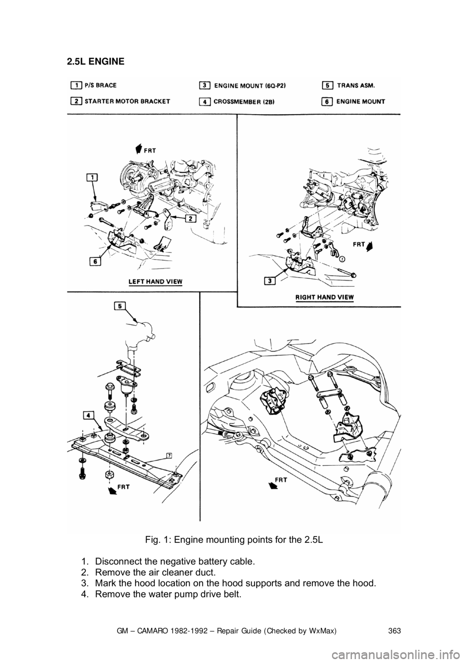
Fig. 1: Engine mountin g points for the 2.5L
1. Disconnect the negative battery cable.
2. Remove the air cleaner duct.
3. Mark the hood location on the hood supports and remove the hood.
4. Remove the water pump drive belt.