center console CHEVROLET CAMARO 1982 Repair Guide
[x] Cancel search | Manufacturer: CHEVROLET, Model Year: 1982, Model line: CAMARO, Model: CHEVROLET CAMARO 1982Pages: 875, PDF Size: 88.64 MB
Page 26 of 875

GM – CAMARO 1982-1992 – Repair Guide (Checked by WxMax) 26
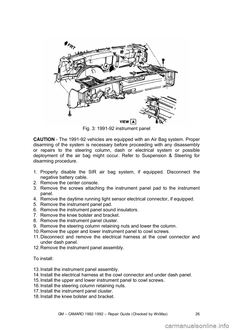
Fig. 3: 1991-92 instrument panel
CAUTION - The 1991-92 vehicles are equipped with an Air Bag system. Proper
disarming of the system is necessary before proceeding with any disassembly
or repairs to the steering column, das h or electrical system or possible
deployment of the air bag might occur. Refer to Suspension & Steering for
disarming procedure.
1. Properly disable t he SIR air bag system, if equipped. Disconnect the
negative battery cable.
2. Remove the center console.
3. Remove the screws attaching the in strument panel pad to the instrument
panel.
4. Remove the daytime running light sens or electrical connector, if equipped.
5. Remove the instrument panel pad.
6. Remove the instrument panel sound insulators.
7. Remove the knee bolster and bracket.
8. Remove the instrument panel cluster.
9. Remove the steering column retaining nuts and lower the column.
10. Remove the upper and lower instrument panel to cowl screws.
11. Disconnect and remove the electric al harness at the cowl connector and
under dash panel.
12. Remove the instrument panel assembly.
To install:
13. Install the instru ment panel assembly.
14. Install the electrical harness at the cowl connector and under dash panel.
15. Install the upper and lower inst rument panel to cowl screws.
16. Install the steering column retaining nuts.
17. Install the instru ment panel cluster.
18. Install the knee bolster and bracket.
Page 27 of 875

GM – CAMARO 1982-1992 – Repair Guide (Checked by WxMax) 27
19. Install the instrument panel sound insulators.
20. Install the inst
rument panel pad.
21. Install the daytime running light sensor electrical connector, if equipped.
22. Install the screws attaching the in strument panel pad to the instrument
panel.
23. Install the center console.
24. Properly arm the SIR air bag syste m, if equipped. Disconnect the negative
battery cable.
DOOR PANELS
REMOVAL & INSTALLATION
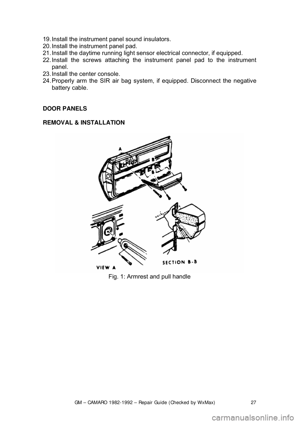
Fig. 1: Armrest and pull handle
Page 289 of 875

GM – CAMARO 1982-1992 – Repair Guide (Checked by WxMax) 289
6. Make sure that levers L, M, and N
are in their Neutral positions (center
detents).
7. Align the holes of levers E, H, and J with the notch in the shifter
assembly (G). Insert an alignment gauge (J-33195) to hold the levers in
this position.
8. Insert swivel S into lever E and insta ll washer Q. Secure with retainer P.
9. Apply rearward pressure (Z) to leve r N. Tighten locknuts R and T (at the
same time) against swivel S to 25 ft. lbs. (34 Nm).
10. Repeat steps 8 and 9 for rod D and levers J and M.
11. Repeat steps 8 and 9 for rod K and levers H and L.
12. Remove the alignment gauge, lower t he vehicle, and check the operation
of the shifting mechanism.
13. Reconnect the negative battery cable.
CLUTCH SWITCH
REMOVAL & INSTALLATION 1. Disconnect the negative battery cable.
2. Remove the sound insulator on 1988- 89 vehicles or the console trim
plate on 1990-92 vehicles.
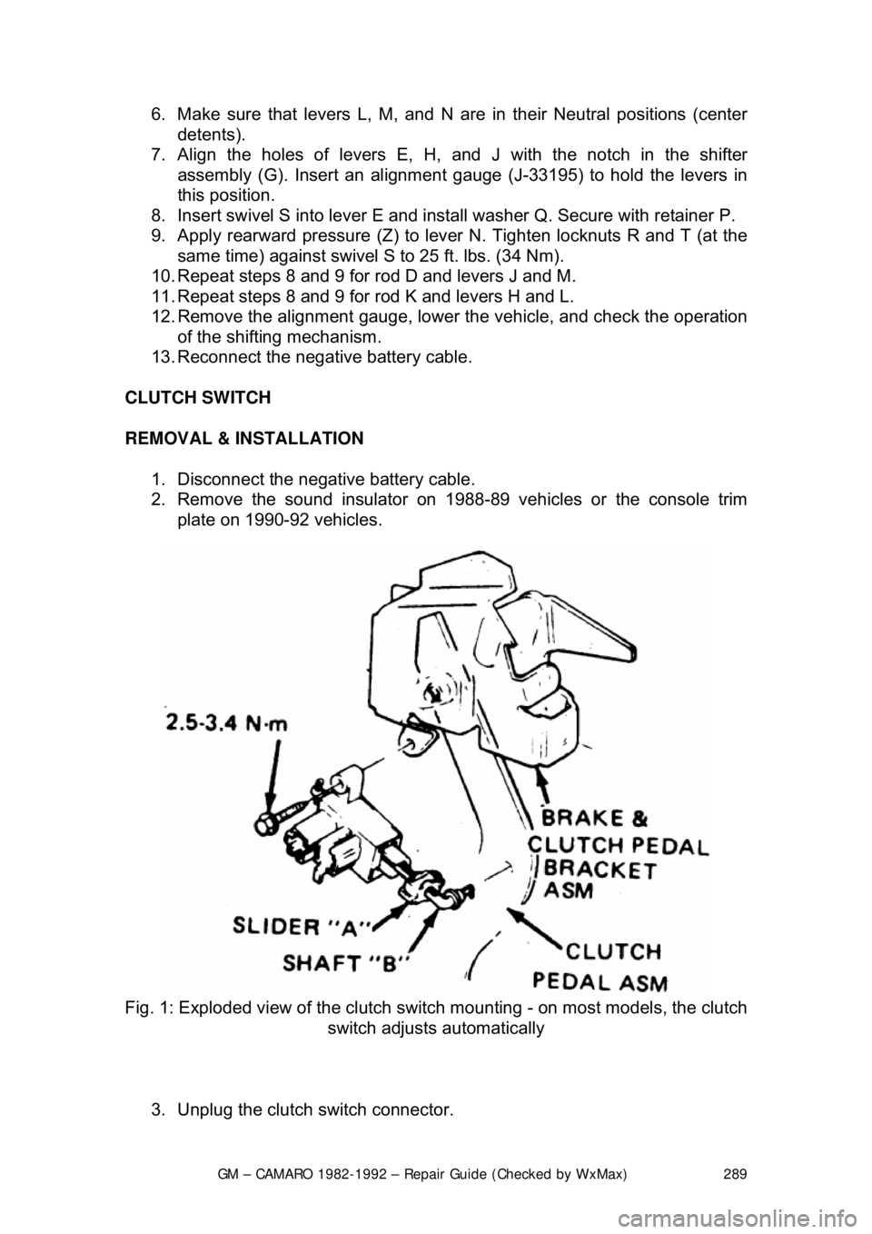
Fig. 1: Exploded view of the clutch swit ch mounting - on most models, the clutch
switch adjusts automatically
3. Unplug the clutch switch connector.
Page 291 of 875

GM – CAMARO 1982-1992 – Repair Guide (Checked by WxMax) 291
6. Remove the console cover.
7. Remove the shifter boot.
8. Remove the shifter mounting bolt
s and remove the shifter assembly.
9. Installation is the reverse of the removal procedure. Adjust the linkage as
detailed earlier.
BACK-UP LIGHT SWITCH
REMOVAL & INSTALLATION 1. Disconnect the negative battery terminal from the battery.
2. At the left-rear of the transmission, the back-up light switch is threaded
into the transmission case. The speed sensor is held in with a separate
bracket. Disconnect the electrical co nnector from the back-up light
switch.
3. Remove the back-up light swit ch from the transmission.
4. To install, reverse the remova l procedures. Coat the threads with
Teflon® tape. Please refer to the to rque chart for specifications. Place
the gear shift lever in the revers e position and check that the back-up
lights work.
EXTENSION HOUSING SEAL
REMOVAL & INSTALLATION
This seal controls transmission oil leakage around the driveshaft. Continued
failure of this seal usually indicates a worn output shaft bushing. If so, there will
be signs of the same wear on the driveshaft where it contacts the seal and
bushing. The seal is available and is fairly simple to install, with the proper tool.
1. Raise and safely support the rear of the vehicle to minimize transmission
oil loss when the driveshaft is removed.
2. Unbolt the driveshaft fr om the differential and center support bearing, if
equipped. Wrap tape around the bearing cu ps to keep them in place on
the universal joint and slide the sh aft out of the transmission.
3. Use an small pry tool to carefully pry out the old seal. Be careful not to
insert the tool too far into the hous ing or the bushing will be damaged.
Page 317 of 875

GM – CAMARO 1982-1992 – Repair Guide (Checked by WxMax) 317
1. Place the shifter lever in the
P position. Remove the negative battery
cable.
2. Turn the key to RUN.
3. Remove the left side instrument panel sound insulator and kick panels.
4. Remove the floor console.
5. Remove the cable nut and clip. Remove the cable from the bracket, move the button to the UP position and unsnap the cable end from the
lever lock pin.
6. Lower the steering column. Remove the cable clips.
To install: 7. Place the shifter lever into the P position and the ignition key to the RUN
position.
8. After installing the cable ends, push the cable connector nose toward th\
e connector as far as possible and push down the lock button.
9. Complete the installation by reversing the removal procedure.
EXTENSION HOUSING SEAL (IN VEHICLE)
REMOVAL & INSTALLATION
This seal controls transmission oil leakage around the driveshaft. Continued
failure of this seal usually indicates a worn output shaft bushing. If so, there will
be signs of the same wear on the driveshaft where it contacts the seal and
bushing. The seal is available and is fairly simple to install, with the proper tool.
1. Raise and safely support rear of t he vehicle to minimize transmission oil
loss when the driveshaft is removed.
2. Unbolt the driveshaft fr om the differential and center support bearing, if
equipped. Wrap tape around the bearing cu ps to keep them in place on
the universal joint and slide the sh aft out of the transmission.
3. Use a small pry tool to carefully pr y out the old seal. Be careful not to
insert the tool too far into the hous ing or the bushing will be damaged.
4. Use an oil seal installation tool to evenly drive the new seal into the
housing. Make sure the tool only cont acts the outer metal portion of the
seal.
5. Install the driveshaft. Torque the uni versal bearing cup retainer bolts to
15 ft. lbs. (20 Nm). Recheck fluid level.
TRANSMISSION
REMOVAL & INSTALLATION 1. Disconnect the negative batte ry cable at the battery.
2. Remove the air cleaner assembly.
3. Disconnect the throttle valve (TV) control cable at the carburetor.