warning CHEVROLET CAMARO 1982 Repair Guide
[x] Cancel search | Manufacturer: CHEVROLET, Model Year: 1982, Model line: CAMARO, Model: CHEVROLET CAMARO 1982Pages: 875, PDF Size: 88.64 MB
Page 45 of 875
GM – CAMARO 1982-1992 – Repair Guide (Checked by WxMax) 45
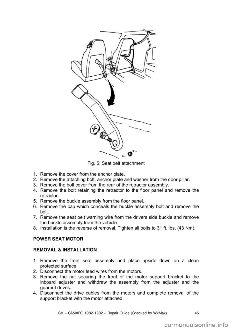
Fig. 5: Seat belt attachment
1. Remove the cover from the anchor plate.
2. Remove the attaching bolt, anchor pl ate and washer from the door pillar.
3. Remove the bolt cover from the rear of the retractor assembly.
4. Remove the bolt retaining the retrac tor to the floor panel and remove the
retractor.
5. Remove the buckle assemb ly from the floor panel.
6. Remove the cap which conceals t he buckle assembly bolt and remove the
bolt.
7. Remove the seat belt warning wire from the drivers side buckle and remove
the buckle assembly from the vehicle.
8. Installation is the reverse of removal. Tighten all bolts to 31 ft. lbs. (43 Nm).
POWER SEAT MOTOR
REMOVAL & INSTALLATION
1. Remove the front seat assemb ly and place upside down on a clean
protected surface.
2. Disconnect the motor feed wires from the motors.
3. Remove the nut securing the front of the motor support bracket to the
inboard adjuster and withdraw the asse mbly from the adjuster and the
gearnut drives.
4. Disconnect the drive cables from t he motors and complete removal of the
support bracket with the motor attached.
Page 49 of 875

GM – CAMARO 1982-1992 – Repair Guide (Checked by WxMax) 49
Upon release of the brake pedal, a spri
ng located inside the master cylinder
immediately returns the master cylinder pistons to the normal position. The
pistons contain check valv es and the master cylinder has compensating ports
drilled in it. These are uncovered as the pistons reach their normal position. The
piston check valves allow fluid to flow to ward the wheel cylinders or calipers as
the pistons withdraw. Then, as the return springs force the brake pads or shoes
into the released position, the excess fluid reservoir through the compensating
ports. It is during the time the pedal is in the released position that any fluid that
has leaked out of the syst em will be replaced through the compensating ports.
Dual circuit master cylinders employ tw o pistons, located one behind the other,
in the same cylinder. The primary pist on is actuated directly by mechanical
linkage from the brake peda l through the power booster. The secondary piston
is actuated by fluid tra pped between the two pistons. If a leak develops in front
of the secondary piston, it moves forward until it bottoms against the front of the
master cylinder, and the fluid trapped betw een the pistons will operate the rear
brakes. If the rear brakes develop a l eak, the primary piston will move forward
until direct contact with the secondary pi ston takes place, and it will force the
secondary piston to actuate the front brakes. In either case, the brake pedal
moves farther when the brakes are applied, and less braking power is available.
All dual circuit systems use a switch to wa rn the driver when only half of the
brake system is operational. This switch is usually located in a valve body which
is mounted on the firewall or the frame below the master cylinder. A hydraulic
piston receives pressure from both circui ts, each circuit's pressure being applied
to one end of the piston. When the pressures are in balance, the piston remains
stationary. When one circuit has a leak, however, the greater pressure in that
circuit during application of the brakes will push the piston to one side, closing
the switch and activating the brake warning light.
In disc brake systems, this valve body also contains a metering valve and, in
some cases, a proportioning valve. The metering valve keeps pressure fro\
m
traveling to the disc brakes on the front wheels until the brake shoes on the rear
wheels have contacted the drums, ensuri ng that the front brakes will never be
used alone. The proportioning va lve controls the pressure to the rear brakes to
lessen the chance of rear wheel lo ck-up during very hard braking.
Warning lights may be tested by depressi ng the brake pedal and holding it while
opening one of the wheel cyli nder bleeder screws. If this does not cause the
light to go on, substitute a new lamp , make continuity checks, and, finally,
replace the switch as necessary.
The hydraulic system may be checked for leaks by applying pressure to the
pedal gradually and steadily. If the pedal sinks very slowly to the floor, the
system has a leak. This is not to be conf used with a springy or spongy feel due
to the compression of air within the lin es. If the system leaks, there will be a
gradual change in the position of the pedal with a constant pressure.
Check for leaks along all lines and at wheel cylinders. If no external leaks are
apparent, the problem is inside the master cylinder.
Page 73 of 875
GM – CAMARO 1982-1992 – Repair Guide (Checked by WxMax) 73
To install:
9. Install the new line or hose, starti
ng with the end farthest from the master
cylinder. Connect the other end, then confirm that both fittings are correctly
threaded and turn smoothly using finger pressure. Make sure the new line
will not rub against any ot her part. Brake lines must be at least 1/2 in.
(13mm) from the steering column and other moving parts. Any protective
shielding or insulators must be rein stalled in the original location.
WARNING - Make sure the hose is NO T kinked or touching any part of the
frame or suspension after installation. These conditions may cause the hose to
fail prematurely.
10. Using two wrenches as bef ore, tighten each fitting.
11. Install any retaining clips or brackets on the lines.
12. If removed, install the wheel and tire assemblies, then carefully lower the
vehicle to the ground.
13. Refill the brake master cylinder re servoir with clean, fresh brake fluid,
meeting DOT 3 specifications. Pr operly bleed the brake system.
14. Connect the negative battery cable.
BLEEDING
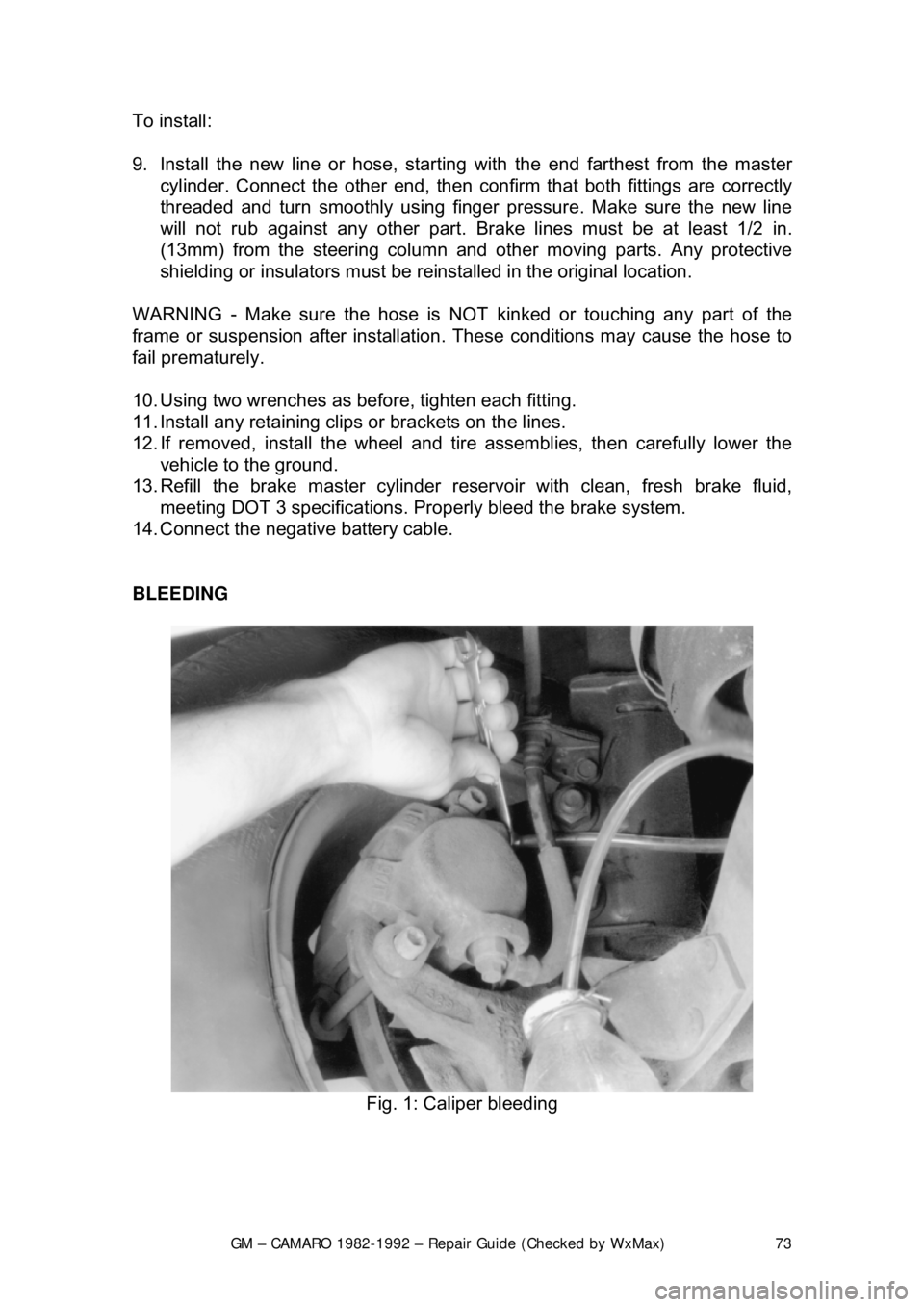
Fig. 1: Caliper bleeding
Page 75 of 875

GM – CAMARO 1982-1992 – Repair Guide (Checked by WxMax) 75
5. Have your assistant sl
owly depress the brake pedal. As this is done, open
the bleeder screw 3/4 of a turn and allow the flui d to run through the tube.
Then close the bleeder screw before the pedal reaches the end of its travel.
Have your assistant slo wly release the pedal. Rep eat this process until no
air bubbles appear in the expelled fluid.
6. Repeat the procedure on the other three br akes, checking the level of fluid in
the master cylinder reservoir often.
7. Upon completion, check the brak e pedal for sponginess and the brake
warning light for unbalanced pressure . If necessary, repeat the entire
bleeding procedure.
FRONT DISC BRAKES
CAUTION - Some brake pads contain asbest os, which has been determined to
be a cancer causing agent. Never clean the brake surfaces with compressed
air! Avoid inhaling any dust from any brake surface! When cleaning brake
surfaces, use a commercially available brake cleaning fluid.
BRAKE PADS
CAUTION - Some brake pads contain asbest os, which has been determined to
be a cancer causing agent. Never clean the brake surfaces with compressed
air! Avoid inhaling any dust from any brake surface! When cleaning brake
surfaces, use a commercially available brake cleaning fluid.
INSPECTION
The pad thickness should be inspected ever y time that the tires are removed for
rotation. The outer pad can be checked by looking in each end, which is the
point at which the highest rate of wear occurs. The inner pad can be checked by
looking down through the inspection hole in the top of the caliper. If the
thickness of the pad is worn to within 0.030 in. (0.8mm) of the rivet at either end
of the pad, all the pads should be replaced.
Always replace all pads on both front wheel s at the same time. Failure to do so
will result in uneven braking action and premature wear.
REMOVAL & INSTALLATION
Page 105 of 875
GM – CAMARO 1982-1992 – Repair Guide (Checked by WxMax) 105
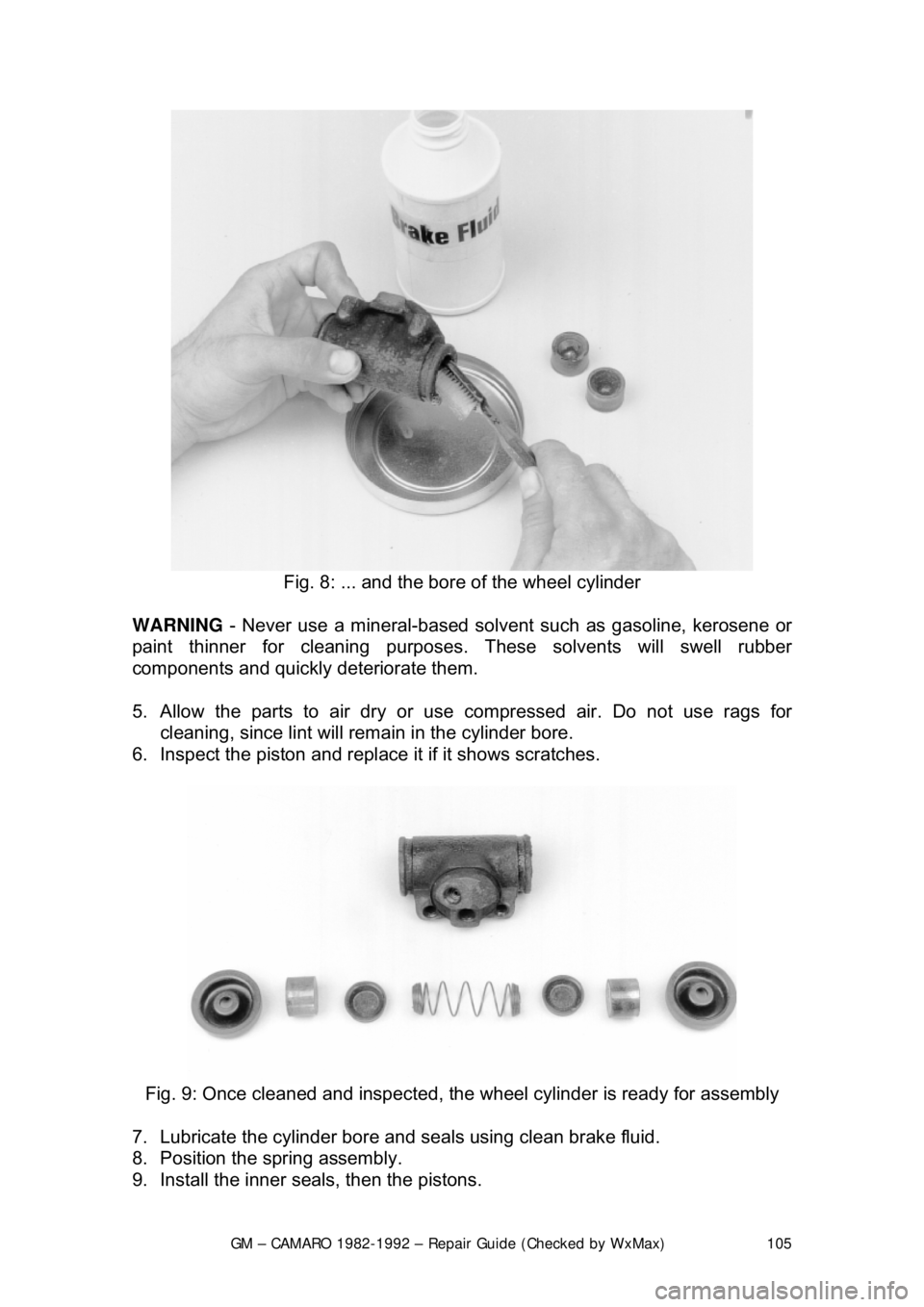
Fig. 8: ... and the bor e of the wheel cylinder
WARNING - Never use a mineral-based solvent such as gasoline, kerosene or
paint thinner for cleaning purposes . These solvents will swell rubber
components and quickly deteriorate them.
5. Allow the parts to air dry or use compressed air. Do not use rags for
cleaning, since lint will rema in in the cylinder bore.
6. Inspect the piston and replace it if it shows scratches.
Fig. 9: Once cleaned and inspected, the wheel cylinder is ready for assembly
7. Lubricate the cylinder bore and s eals using clean brake fluid.
8. Position the spring assembly.
9. Install the inner seals, then the pistons.
Page 122 of 875
GM – CAMARO 1982-1992 – Repair Guide (Checked by WxMax) 122
REAR DISC BRAKES
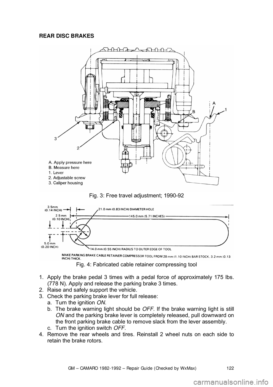
Fig. 3: Free trav el adjustment; 1990-92
Fig. 4: Fabricated cable retainer compressing tool
1. Apply the brake pedal 3 times with a pedal force of approximately 175 lbs.
(778 N). Apply and release t he parking brake 3 times.
2. Raise and safely support the vehicle.
3. Check the parking brake lever for full release: a. Turn the ignition ON.
b. The brake warning light should be OFF. If the brake warning light is still
ON and the parking brake lever is comple tely released, pull downward on
the front parking brake cable to remove slack from the lever assembly.
c. Turn the ignition switch OFF.
4. Remove the rear wheels and tires. Reinstall 2 wheel nuts on each side to
retain the brake rotors.
Page 137 of 875

GM – CAMARO 1982-1992 – Repair Guide (Checked by WxMax) 137
voltage) is present; it only means that so
me voltage is present. It is advisable
before using the test light to touch its ground clip and probe across the battery
posts or terminals to make sure the light is operating properly.
WARNING - Do not use a test light to probe electronic ignition, spark plug or
coil wires. Never use a pick-type test light to probe wiring on computer
controlled systems unless spec ifically instructed to do so. Any wire insulation
that is pierced by the test light pr obe should be taped and sealed with silicone
after testing
Like the jumper wire, the 12 volt test li ght is used to isolate opens in circuits.
But, whereas the jumper wire is used to bypass the open to operate the load,
the 12 volt test light is us ed to locate the presence of voltage in a circuit. If the
test light illuminates, there is power up to t hat point in the circuit; if the test light
does not illuminate, there is an open circui t (no power). Move the test light in
successive steps back toward the power source until the light in the handle
illuminates. The open is between the pr obe and a point which was previously
probed.
The self-powered test light is similar in design to the 12 volt test light, but
contains a 1.5 volt penlight battery in the handle. It is most often used in place
of a multimeter to check for open or shor t circuits when power is isolated from
the circuit (continuity test).
The battery in a self-powered test light does not provide much current. A weak
battery may not provide enough power to illuminate the test light even when a
complete circuit is made (especially if there is high resistance in the circuit).
Always make sure that the test battery is strong. To check the battery, briefly
touch the ground clip to the pr obe; if the light glows brightly, the battery is strong
enough for testing.
A self-powered test light should not be used on any co mputer controlled system
or component. The small amount of electr icity transmitted by the test light is
enough to damage many electr onic automotive components.
MULTIMETERS
Multimeters are an extremely useful tool for troubleshooting electrical problems.
They can be purchased in either analog or digital form and have a price range
to suit any budget. A multimeter is a voltmeter, ammeter and ohmmeter (along
with other features) combined into one instrument. It is often used when testing
solid state circuits because of its hi gh input impedance (usually 10 megaohms
or more). A brief description of the mult imeter main test functions follows:
• Voltmeter - the voltmeter is used to measure voltage at any point in a
circuit, or to measure the voltage drop across any part of a circuit.
Voltmeters usually have various scales and a selector switch to allow the
reading of different volt age ranges. The voltmeter has a positive and a
negative lead. To avoid damage to the meter, always connect the
negative lead to the negative (—) side of the circ uit (to ground or nearest
Page 138 of 875

GM – CAMARO 1982-1992 – Repair Guide (Checked by WxMax) 138
the ground side of the circuit) and
connect the positive lead to the
positive (+) side of the circuit (to t he power source or the nearest power
source). Note that the negative voltme ter lead will always be black and
that the positive voltmeter will alwa ys be some color other than black
(usually red).
• Ohmmeter - the ohmmeter is designed to read resistance (measured in
ohms) in a circuit or component. Mo st ohmmeters will have a selector
switch which permits the measurement of different ranges of resistance
(usually the selector swit ch allows the multiplication of the meter reading
by 10, 100, 1,000 and 10,000). Some ohmmeters are "auto-ranging"
which means the meter itself will dete rmine which scale to use. Since the
meters are powered by an internal battery, the ohmmeter can be used
like a self-powered test light. When the ohmmeter is connected, current
from the ohmmeter flows through the ci rcuit or component being tested.
Since the ohmmeter's internal resi stance and voltage are known values,
the amount of current flow throug h the meter depends on the resistance
of the circuit or component being test ed. The ohmmeter can also be used
to perform a continuity test for suspected open circuits. In using the
meter for making continuity checks, do not be concerned with the actual
resistance readings. Zero resistance, or any ohm reading, indicates
continuity in the circui t. Infinite resistance indi cates an opening in the
circuit. A high resistance reading w here there should be none indicates a
problem in the circuit. Checks for s hort circuits are made in the same
manner as checks for open circuits, ex cept that the circuit must be
isolated from both power and normal gr ound. Infinite resistance indicates
no continuity, while zero resi stance indicates a dead short.
WARNING - Never use an ohmmeter to check the resistance of a component or
wire while there is volt age applied to the circuit
• Ammeter - an ammeter measures the am ount of current flowing through
a circuit in units called amperes or amps. At normal operating voltage,
most circuits have a characteristic amount of amperes, called "current
draw" which can be measured usi ng an ammeter. By referring to a
specified current draw rating, then measuring the amperes and
comparing the two values, one can det ermine what is happening within
the circuit to aid in diagnosis. An open circuit, for example, will not allow
any current to flow, so the amme ter reading will be zero. A damaged
component or circuit will have an incr eased current draw, so the reading
will be high. The ammeter is always connected in series with the circuit\
being tested. All of the current that normally flows through the circuit
must also flow through the ammeter; if there is any other path for the
current to follow, the ammeter readi ng will not be accurate. The ammeter
itself has very little resistance to curr ent flow and, therefore, will not affect
the circuit, but it will measure current draw only when the circuit is closed
and electricity is flowing. Excessive current draw can blow fuses and
drain the battery, while a reduced current draw can cause motors to run \
slowly, lights to dim and other components to not operate properly.
Page 143 of 875
GM – CAMARO 1982-1992 – Repair Guide (Checked by WxMax) 143
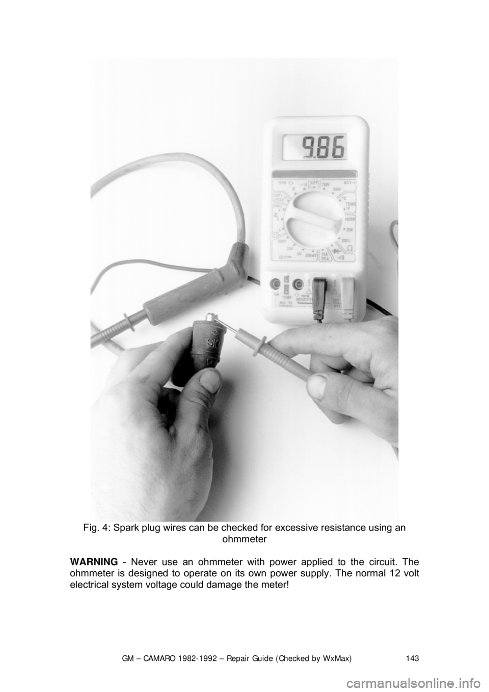
Fig. 4: Spark plug wires can be checked for excessive resistance using an
ohmmeter
WARNING - Never use an ohmmeter with power applied to the circuit. The
ohmmeter is designed to operate on its own power supply. The normal 12 volt
electrical system voltage could damage the meter!
Page 147 of 875

GM – CAMARO 1982-1992 – Repair Guide (Checked by WxMax) 147
SYSTEM OPERATION
The main portions of the SIR system
are the deployment loops and the
Diagnostic Energy Reserve Module (D ERM). The main function of the
deployment loops is to supply current through the inflator module(s), which will
cause deployment of the air bag(s) in t he event of a frontal crash of sufficient
force. The arming sensor, SIR coil assembly (driver side only), passen\
ger
inflator module jumper (passenger side only), inflator module(s), passenger
compartment discriminating sensor and fo rward discriminating sensor make up
the deployment loops.
The DERM has two functions. One to supply the deployment loops with a 36
volt reserve to ensure sufficient energy is available to deploy the airbag(s) if the
battery voltage feed to the arming sensor is lost during a frontal crash. Another
function is SIR electrical system diagnostics.
The arming sensor switches power to th e inflator module(s) on the high side
(power side) of the deployment loops. Ei ther of the discriminating sensors can
supply ground to the inflator module(s) on the low side (ground side) of the loop.
The inflator module(s) ar e only supplied sufficient cu rrent to deploy when the
arming sensor and at least one of the two discriminating sensors are closed
simultaneously.
SYSTEM COMPONENTS
DIAGNOSTIC ENERGY RESERVE MODULE
The DERM is designed to perform the following functions in the SIR system:
• Energy Reserve - Maintains 36 volt energy reserve(s) to provide
deployment energy when the vehicle volt age is low or lost in a frontal
impact
• Malfunction Detection - Performs diagnostic monitoring of the SIR
system electrical components
• Malfunction Recording - Provides diagnostic trouble code information
• Frontal Crash Recording - Record s the SIR system status during a
frontal crash
WARNING LAMP
The "INFL REST" or "AIR BAG" warning lamp is used to do the following:
• Verify lamp and DERM oper ation by flashing seven to nine times when
the ignition key is first turned ON
• Warn the driver of SIR electrical system faults which could potentially
affect the operation of the SIR system
• Provide diagnostic information by fl ashing the fault codes when the
diagnostic mode is enabled