washer fluid CHEVROLET CAMARO 1982 Repair Guide
[x] Cancel search | Manufacturer: CHEVROLET, Model Year: 1982, Model line: CAMARO, Model: CHEVROLET CAMARO 1982Pages: 875, PDF Size: 88.64 MB
Page 66 of 875

GM – CAMARO 1982-1992 – Repair Guide (Checked by WxMax) 66
4. Remove nuts and lockwashers that se
cure booster to firewall and remove
booster from engine compartment.
5. Install by reversing removal procedure. Make sure to check operation of stop
lights. Allow engine vacuum to build before applying brakes.
COMBINATION VALVE
REMOVAL & INSTALLATION
This valve is not repairable and only serviced as a complete assembly.
1. Disconnect the hydraulic lines from t he valve. Plug the lines to prevent fluid
loss and dirt contamination.
2. Disconnect the electrical connection.
3. Remove the valve.
To install:
4. Position the valve.
5. Connect the electrical connection.
6. Connect the hydraulic lines to the valve.
7. Bleed the brake system.
Page 91 of 875

GM – CAMARO 1982-1992 – Repair Guide (Checked by WxMax) 91
Avoid inhaling any dust from
any brake surface! When cleaning brake surfaces,
use a commercially available brake cleaning fluid.
1. Remove the caliper by following instru ctions of caliper removal procedure.
2. Remove dust cap, cotter pin, castle nut, thrust washer and outside wheel
bearing. Pull the disc/hub assembly from the steering knuckle.
To install:
3. Position the disc/hub assembly to t he spindle/steering knuckle. Install the
outside wheel bearing, thru st washer and castle nut. Tighten the castle nut
until the bearing is s nug. Back off the nut
1/4 turn. Refer to Suspension &
Steering for details on wheel bearing remo val, installation, and adjustment.
Install a new cotter pin and dust cap.
4. Install the brake caliper.
INSPECTION
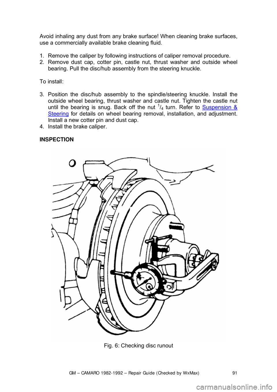
Fig. 6: Checking disc runout
Page 113 of 875

GM – CAMARO 1982-1992 – Repair Guide (Checked by WxMax) 113
1. Remove 2/3 of the brake fluid from the ma
ster cylinder. Raise the car.
Remove the wheel. Reinstall a wheel nut, with the flat side toward the rotor,
to hold the rotor in place.
2. Loosen the parking brake cable at the equalizer. At the caliper, remove the
parking brake cable, damper and spring from the lever.
3. Hold the parking brake lever and re move the lock nut. Remove the lever,
seal and anti-friction washer.
4. Position a C-clamp ov er the caliper and force the piston into its bore.
Remove the C-clamp. Rein stall the lever, seal and nut to the caliper.
5. Loosen the brake tube nut and disc onnect the brake tube from the caliper.
Plug the tube to prevent t he loss of brake fluid.
At the right rear wheel, it may be necessary to remove the rear bolt from the
lower control arm to allow the lower caliper mounting bolt to be removed.
6. Remove the mounting bolts using a
3/8 in. Allen head socket. Remove the
caliper and inspect the mounting bolts for corrosion. If necessary, replace
the mounting bolts.
To install:
7. Place the caliper onto the rotor and install the m ounting bolts. Torque the
mounting bolts to 30-45 ft . lbs. (40.7-61 Nm).
8. Install a new anti-friction washer and lubricate the lever with silicone brake
lube. Install the lever on the actuator with the lever pointing down. Rotate the
lever toward the front of the car and hol d while installing the nut. Torque the
nut to 30-40 ft. lbs. (40.7-54.2 Nm), then rotate the lever back against the
stop on the caliper.
9. Install damper and spring. Connect the parking brake cable. Tighten the
cable at the equalizer until the lever starts to move off the stop on the
caliper, then loosen the adjustment unt il the lever moves back against the
stop.
10. Remove the nut holding the rotor in place and install the wheel. Lower the
car and fill the master cylin der with brake fluid.
1989-92 MODELS
1. Raise and safely support the vehicle.
2. Loosen the parking brake cable at the equalizer.
3. Remove the wheel and tire assembly. Inst all 2 wheel nuts to retain the rotor.
4. Remove the bolt, inlet fitting and was hers from the caliper housing. Plug the
holes in the caliper housing and inlet fitting.
5. Remove the caliper lever return spri ng only if it is defective. Discard the
spring if the coils are opened.
6. Disconnect the parking brake cable from the caliper lever and caliper
bracket.
7. Remove the 2 caliper guide pin holes.
8. Remove the caliper housing from the rotor and mounting bracket.
To install:
Page 117 of 875

GM – CAMARO 1982-1992 – Repair Guide (Checked by WxMax) 117
5. Remove the shaft seal and washer.
6. Remove the dust boot. Be careful not to scratch the housing bore.
7. Remove the locator retainer if so
equipped. Remove the piston locator if so
equipped.
8. Remove the piston seal usi ng a wooden or plastic tool.
9. Remove the bleeder screw, bolt, fi tting, and copper washer. Remove the
bracket only if it is damaged.
10. Inspect caliper bore for scoring, nicks, corrosion, and wear. Use crocus cloth
for light corrosion. Replace caliper if bore will not clean up.
To install:
11. Replace the bleeder screw, bolt, fitting, and copper washer.
12. Install the piston. Lubricate seal s and piston with brake fluid prior to
reinstallation.
13. Install the locator retainer if so equi pped. Install the piston locator if so
equipped.
14. Install the dust boot.
15. Install the shaft seal and washer.
16. Install actuator scr ew to the housing.
17. Install the nut, lever, lever seal, and anti-friction washer. It may be necessary
to rotate the parking brake lever away from the stop to install the nut. Torque
the nut 30-40 ft. lbs. (41-54 Nm) and ro tate the lever back to the stop.
18. Install the shoe dampening spri ng to the end of the piston.
It may be necessary to move the parking brake lever off the stop, extending the
piston slightly, making the dampening spring groove acce ssible. If the piston is
extended, push it back into the caliper before installing the caliper on the car.
1989-92 MODELS
1. Remove the caliper assembly. Remove the 2 collar return springs from the
actuating collar. Remove the actuator collar assembly with parts attached
out of the housing.
2. Remove the clamp rod and compliance bushing.
3. Remove the boot retainers, 2 boots and pushrod from the compliance
bushing. Discard the retainers and boots.
4. Remove the preload spring from the retainer.
5. Using compressed air directed into the brake hose port, carefully extract
piston.
CAUTION - Do not place fingers between piston and brake shoe flange, or
personal injury may occur when piston breaks free from bore. Cover caliper
assembly with a rag to prevent brake fluid from spraying when piston is
extracted
6. Inspect and clean piston and bore a ssembly for cracks or scoring.
7. Remove the piston seal.
8. Remove the bleeder valve.
Page 194 of 875

GM – CAMARO 1982-1992 – Repair Guide (Checked by WxMax) 194
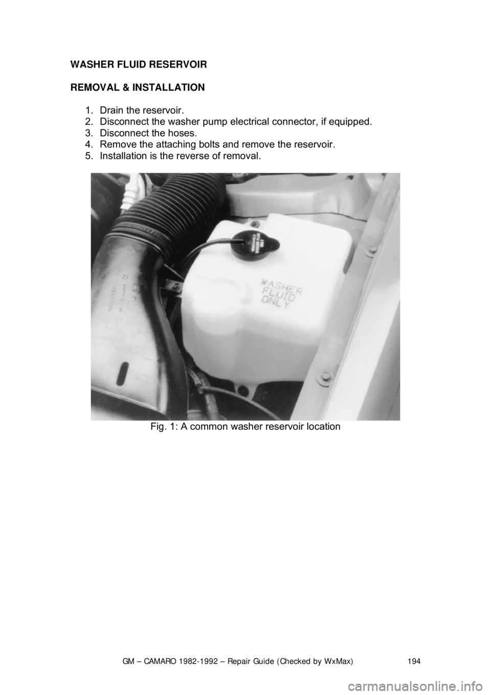
WASHER FLUID RESERVOIR
REMOVAL & INSTALLATION
1. Drain the reservoir.
2. Disconnect the washer pump elec trical connector, if equipped.
3. Disconnect the hoses.
4. Remove the attaching bolts and remove the reservoir.
5. Installation is the reverse of removal.
Fig. 1: A common washer reservoir location
Page 336 of 875

GM – CAMARO 1982-1992 – Repair Guide (Checked by WxMax) 336
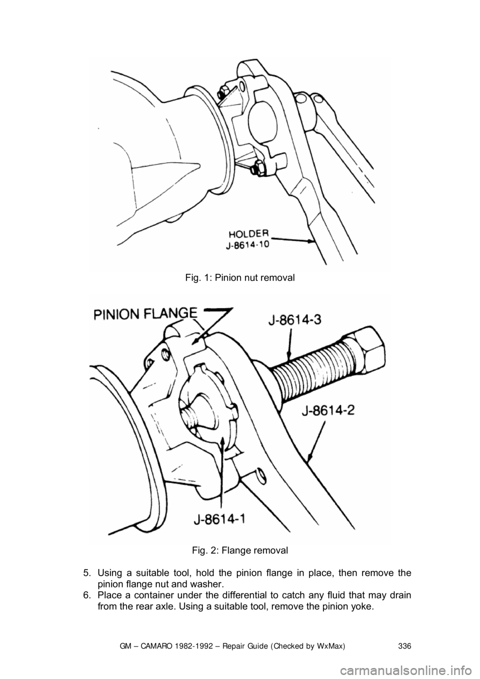
Fig. 1: Pinion nut removal
Fig. 2: Flange removal
5. Using a suitable tool, hold the pini on flange in place, then remove the
pinion flange nut and washer.
6. Place a container under the differential to catch any fluid that may drain
from the rear axle. Us ing a suitable tool, remove the pinion yoke.
Page 338 of 875

GM – CAMARO 1982-1992 – Repair Guide (Checked by WxMax) 338
seal preload. Turn the torque wrenc
h smoothly for several rotations and
record the amount of preload as the a ssembly is turning, not the initial
force required to start the assembly moving.
Preload is measured as the amount of torque required to turn the assembly.
5. Using a suitable tool to hold the pi nion yoke in place, remove the pinion
yoke nut and washer.
6. Place a suitable contai ner under the differential to catch any fluid that
may drain from the rear axle. Using a suitable tool, remove the pinion
flange.
7. Use a suitable tool to remove the pinion seal.
To install: 8. Inspect the seal surface of the pinion flange for tool marks, nicks or
damage and replace, as necessary. Examine the carrier bore and
remove any burrs that might cause leaks around the outside of the seal.
9. Install the seal 0.010 in. (0.2 5mm) below the flange surface using a
suitable seal installer.
10. Apply suitable seal lubricant to t he outer diameter of the pinion flange
and the sealing lip of the new seal.
11. Install the pinion flan ge on the drive pinion by taping with a soft hammer
until a few pinion threads projec t through the pinion flange.
12. Install the washer and pinion fla nge nut. While holding the pinion flange,
tighten the nut a little at a time and turn the drive pinion several
revolutions after each tightening, to set the bearing rollers. Check the
preload each time with a suitable inch pound to rque wrench until the
preload is 5 inch lbs. (0.6 Nm) more then the reading obtained during
disassembly.
13. Install the driveshaft.
14. Install the rear wheels and tires. Check and add the correct lubricant, as
necessary.
AXLE HOUSING
REMOVAL & INSTALLATION 1. Raise the vehicle and support it sa fely. Be sure that the rear axle
assembly is supported safely.
2. Disconnect shock absorbers from ax le. Remove the wheel assemblies.
3. Mark driveshaft and pinion flange, then disconnect driveshaft and support out of the way.
4. Remove brake line junction block bolt at axle housing. If necessary,
disconnect the brake lines at the junction block.
Page 716 of 875

GM – CAMARO 1982-1992 – Repair Guide (Checked by WxMax) 716
INJECTOR REPLACEMENT
Use care in removing injectors to prev
ent damage to the electrical connector
pins on top of the injector, the fuel injector fuel filter and nozzle. The fuel injector
is serviced as a complete assembly on ly and should never be immersed in any
type of cleaner.
SINGLE INJECTOR UNITS 1. Relieve the fuel system pressure.
2. Remove the air cleaner.
3. Detach the injector connector by squeezing the two tabs together and
pulling straight up.
4. Remove the screws securing the fuel meter cover. Note the location of
any short screws for correct placement during reassembly.
CAUTION - DO NOT remove the four screws se curing the pressure regulator to
the fuel meter cover. The fuel pressure regulator includes a large spring under
heavy tension which could cause personal injury if released.
5. With the old fuel meter gasket in place to prevent damage to the casting,
use a prytool and fulcrum to pry the inje ctor carefully until it is free from
the fuel meter body.
6. Remove the injector.
7. Remove the large O-ring and steel back-up washer at the top of the
injector cavity in the fuel meter body.
8. Remove the small O-ring located at the bottom of the injector cavity.
To Install: 9. Lubricate the new, small O-ring with automatic transmission fluid; then,
push the new O-ring on the nozzle end of the injector up against the
injector fuel filter.
10. Install the steel backup washer in the recess of the fuel meter body.
Lubricate the new large O-ring with automatic transmission fluid, then
install the O-ring directly above t he backup washer, pressing the O-ring
down into the cavity recess. The O-ri ng is properly installed when it is
flush with the casting surface.
WARNING - Do not attempt to reverse this procedure and install the backup
washer and O-ring after the injector is located in the cavity. To do so will
prevent proper seating of the O-ring in th e cavity recess which could result in a
fuel leak and possible fire.
11. Install the injector by using a pushing/twisting mo tion to center the nozzle
O-ring in the bottom of the injector cavity and aligning the raised lug on
the injector base with the notch cast into the fuel meter body. Push down
on the injector making sure it is fully seated in the cavity. Injector
installation is correct when the lug is seated in the notch and the
electrical terminals are parallel to the throttle shaft.
Page 784 of 875

GM – CAMARO 1982-1992 – Repair Guide (Checked by WxMax) 784
b. If fluid is warm, the le
vel should be close to the ADD mark, either
above or below.
c. If fluid is too hot to touc h, the level should be at the FULL mark.
3. If the fluid level is low, add Dexr on®II automatic transmission fluid (ATF)
through the dipstick tube. This is eas ily done with the aid of a funnel.
Check the level often as you are f illing the transmission. Be extremely
careful not to overfill it. Overfilling will cause slippage, seal damage and
overheating. Approximately 1 pint (0.473L) of ATF will raise the fluid level
from one notch/line to the other.
If the fluid on the dipstick appears discolored (brown or black), or smells burnt,
serious transmission troubles, probably due to overheating, should be
suspected. The transmission should be inspected by a qualified technician to
locate the cause of the burnt fluid.
DRAIN AND REFILL
Please refer to the "PAN AND FILTER SERVICE" procedure listed in this
section.
PAN AND FILTER SERVICE
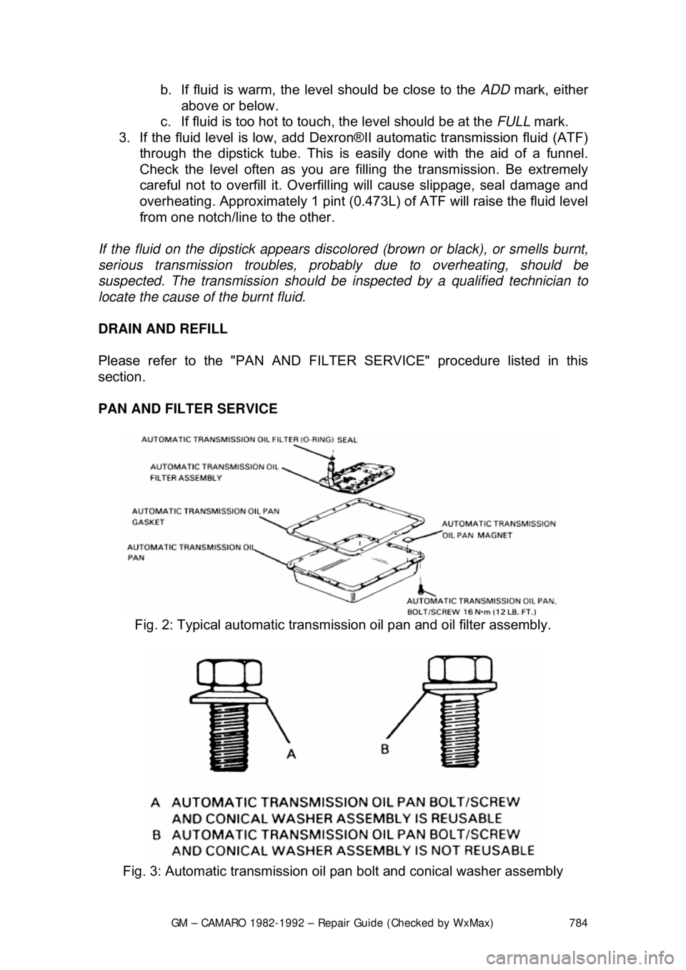
Fig. 2: Typical automatic transmiss ion oil pan and oil filter assembly.
Fig. 3: Automatic transmission oil pan bolt and conical washer assembly
Page 785 of 875

GM – CAMARO 1982-1992 – Repair Guide (Checked by WxMax) 785
The automatic transmission fluid and fi
lter should be changed every 15,000
miles (24,000km) if your Camaro is driven in heavy city traffic in hot weather, in
hilly or mountainous terrain, frequent trailer pulling, or uses such as found in
taxi, police car or delivery service. If your Camaro is driven under other than
listed above conditions, change the fl uid and filter every 30,000 miles
(48,300km).
1. Raise and support the car on jackst ands. Place an oil catch pan under
the transmission.
2. Remove the oil pan bolts fr om the front and sides only.
3. Loosen rear oil pan bolts approximately 4 turns.
WARNING - Do not damage the transmission case or oil pan sealing surfaces.
4. Lightly tap the oil pan with a rubber mallet or gently pry it downward to
allow fluid to drain.
5. Remove the remaining oil pan bolt s, then remove the oil pan and pan
gasket.
6. Remove the filter and seal.
7. Clean the transmission case and oi l pan gasket surfaces with suitable
solvent and air dry. Make sure to re move all traces of the old gasket.
To install: 8. Coat the seal with a sm all amount of Transjel®.
9. Install the new s eal onto the filter.
10. Install the new filter into the case.
11. Install the oil pan and new gasket.
On 1991 and later vehicles, inspect t he oil pan screws and washer assemblies.
The screws must not be used if the coni cal washer is reversed. Failure to
replace the screw and washer assembly may result in improper fastening of
system components.
12. Install the oil pan bolts and tighten them to 12 ft. lbs. (16 Nm).
13. Lower the car.
14. Fill the transmission to proper level with Dexron®II fluid.
15. Check cold fluid level reading fo r initial fill. Do not overfill the
transmission.
16. Follow the fluid level che ck procedure described before.
17. Check the oil pan gasket for leaks.