clock CHEVROLET CAVALIER 1984 1.G Owners Manual
[x] Cancel search | Manufacturer: CHEVROLET, Model Year: 1984, Model line: CAVALIER, Model: CHEVROLET CAVALIER 1984 1.GPages: 105, PDF Size: 24.23 MB
Page 39 of 105
Downloaded from www.Manualslib.com manuals search engine '" ,
t:l
STANDARD INSTRUMENT CLUSTER
IJ
12
OPTIONAL INSTRUMENT CLUSTER
~~~~-:'----,~~:
l'l
1l
10
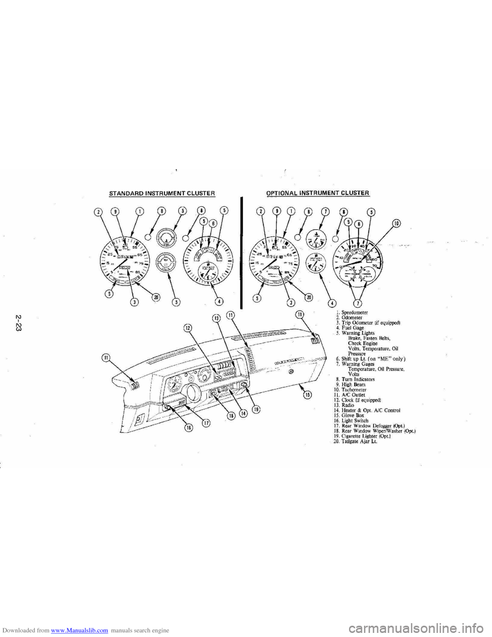
L Speedometer 2. Odometer 3. Trip ()jometer lif equipped) 4. Fuel Gage 5. Warning Lights Brake, Fasten Belts, Check. Engine Volts, Temperature, Oil Pressure 6. Shift up Lt. (on "ME"only) 7. Warning Gages Temperature, on Pressure, Volts 8. Turn Indicators 9. High Beam 10. Tachomet er 11. A/C Outlet 12. Clock. (if equipped) 13. Radio 14. Heater & Opt. Ale Control 15. Glove Box 16. Lig ht Switch 17. Rear Window Defogger (Opt.) 18. Rear Window WiperlWasher (Opt.) 19. Cigare tt e Lighter (Opt.) 20, Tailgat e Ajar Lt.
Page 40 of 105
Downloaded from www.Manualslib.com manuals search engine Engine Coolant Temperature Gage
This optional gage is located in the instrument cluster. If the gage shows that
an overheat condition exists-as indicated by pointer moving beyond the
center of the band immediate action by the driver is required. If an overheat
condition is shown, see "Engine
Cooling System Overheating" in "In Case of
Emergency,"
Section 3 of this manual. The coolant temperature indication will VaIY with air temperature and operating conditions. The ignition must be in
"Run" for accurate readings. Prolonged driving or idling in very hot weather
may cause the pointer to move beyond the center of the gage. Make a practice
of scanning this and other gages
while driving, especially in hot weather and!
or when the
vehicle is under load.
CAUTION: II the Engine Coolant Temperature Gage shows an overheat condition or you have other reason to suspect the engine may be overheating, continued operation of the engine EVEN FOR A SHORT TIME may result in a fire and the risk of personal injury and/or severe vehicle damage. Take immediate action as outlined under "Engine Cooling System Overheating" in "In Case of Emergency," Section 3.
Oil Pressure Gage
The oil pressure gage indicates the pressure at which oil is being delivered to
the vaIiOUS paIls of the engine requiring lubrication. Pressures registered by
the gage may
vBIY according to outside air temperatures or weight of oil being
used. Oil pressure of a cold engine being operated at a given speed will be
somewhat higher than when the engine is at normal operating temperature at
the
SaIne speed. Prolonged high speed operation on a hot day at the given
speed will
resuH in somewhatlower oil pressure readings. Readings of 205 to
275 kPa
(30 to 40 psi) may be considered normal during moderate road
speeds of 35 to 40 mph (55 to 60 km!h) with the engine at proper operating
temperature. Gage readings which are consistently high
or low under these conditions may indicate lubrication system and/ or engine malfunction.
Light Switch
The three· position light switch controls the headlights, taillights, paIking lights,
sidemaIker lights,
instrument lights and dome lights.
Instrument light intensity can be varied by turning knob clockwise or
counterclockwise. Full counterclockwise position turns on interior light.
The headlight circuit is protected by a circuit breaker in the
light switch. An overload on the breaker will cause the lights to "flicker" on and off. If this
condition
develops, have your headlight wiring checked immediately. The
headlight beaIn changer is located in the Turn Signal Lever; for operation see
Section 2 under heading "Turn Signal and Muiji-Function Lever."·
Headlight High Beam Indicator Light
The headlights of your vehicle have. high and low beams to provide you with
proper nighttime visibility for most driving conditions. The
"low" beams are
used during most city driving. The
"high" beams are especially useful when
driving on daIk roads since they provide long range illumination. The headlight
beam indicator light (located on the speedometer face) will be ON whenever
the high beams or "brights" are in use. The turn
signal lever controls the
headlight beaIns and is described in "Steering Column Controls."
2-24
Page 47 of 105
Downloaded from www.Manualslib.com manuals search engine Store cassettes away from extreme heat or direct sunlight. Protect the open ends from dirt or damage; store them in their original cases or other protective
cases. Cassettes eventually wear out and you may need to replace them if
they become noisy. Clean the pickup head, tape guide and capstan (revolving
metal
post) after every 100 hours of operation . Use a colton-tipped swab
dippec in rubbing
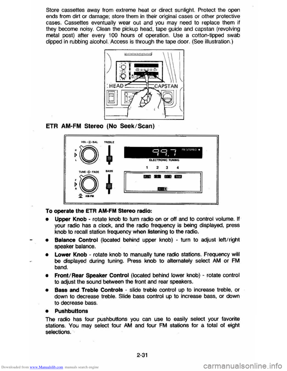
alcohol. Access is through the tape door. (See illustration.)
ETR AM-FM Stereo (No Seek /Scan)
To operate \he ETA AM-FM Stereo radio:
• Upper Knob -rotate knob to turn radio on or off and to control volume. H your radio has a clock, and the radio frequency is being displayed, press
knob to
recall station frequency when listening to the radio.
• Balance Control (located behind upper knob) -turn to adjust left!right
speaker balance .
•
Lo_ Knob -rotate knob to manually tune radio stations , Frequency will
be displayed during tuning. Press knob to aHernately select />M or FM
band.
• Front! Rear Speaker Control (located behind lower knob) -rotate control
to adjust the sound between the front and rear speakers.
• Bass and Treble Controls -slide treble control up to increase treble, or
down to decrease treble. Slide bass control up to increase bass, or down
to decrease bass.
• Pushbutton.
The radio has four pushbuttons you can use to easily select your favorite
stations , You may select four />M and four FM stations for a total of eight
selections. .
2-31
Page 49 of 105
Downloaded from www.Manualslib.com manuals search engine To listen to an earlier selection, slide EJECT button to the right ("REV") until it locks. When the tape reaches the end, the EJECT button will automatically
return to center position and the tape will resume playing.
To stop reverse at any time, return the EJECT button to its center position.
NOTE: Belore turning off ignition, eject the cassette tape. Insertion 01 the
cassette tape cartridge overrides the radio and the time-ol-day
will be
displayed continuously.
For best results, use only cassettes which are 30 to 60 minutes in length.
ETR AM-FM Stereo (Seek/Scan) with Cassette 5-Band
Equalizer and Clock
VDL+BAL
~o ~ PAOG·ACL
TUNE --Y-FADE
~O
~ AM-FM
o,~ -, 'M ST
".f AM.
SCAN 1 2 3 4 SEEK
-IlIIIIIIlIIIII IIDIDI IBIIIIII IIDDID IDIDID DIIIIIII!IIIII
PWR LOUD
DIb! AUTO REVERSE
DNIl .Cr02
CD
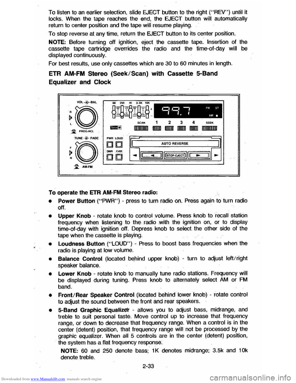
To operate the ETR AM-FM Stereo radio:
• Power Button ("PWR") -press to turn radio on. Press again to turn radio
off.
• Upper Knob -rotate knob to control volume. Press knob ti:> recall station
frequency when listening to the radio with the ignition on, or to display time-ol-day with ignition off. Depress knob to select the other side 01 the
tape when the cassette
is playing.
•
Loudness Button ("LOUD") - Press to boost bass frequencies when the
radio is
playing at low volume.
• Balance Control (located behind upper knob) -turn to adjust left/right
speaker balance.
• Lower Knob -rotate knob to manually tune radio stations. Frequency will
be displayed during tuning. Press knob to alternately select AM or FM
band.
• Front/Rear Speaker Control (located behind lower knob) -rotate control
to adjust the sound between the lront and rear speakers.
• 5-Band Graphic Equalizl!i' -allows you to adjust bass, midrange, and treble to suit personal taste. Move control up to increase that frequency
range, or down to decrease that frequency range. When a control is in the
center (detent) position, that
Irequency range will not be processed by the
graphic equalizer. When all 5 controls are in the center (detent) position,
the system has a flat frequency response:
NOTE: 60 and 250 denote bass; 1 K denotes midrange; 3.5k and 10k
denote treble.
2-33
Page 57 of 105
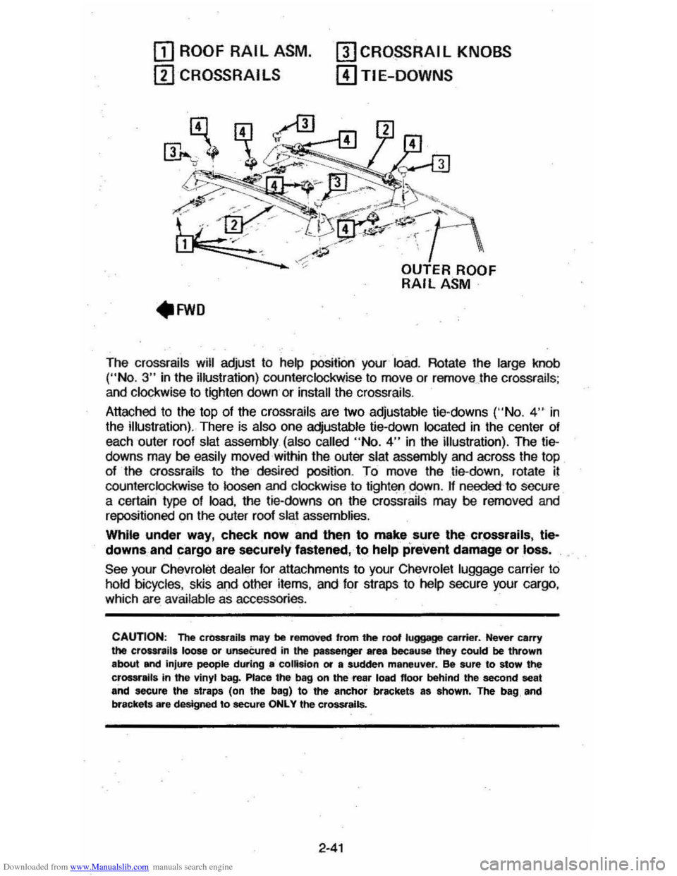
Downloaded from www.Manualslib.com manuals search engine OJ ROOF RAIL ASM.
ill CROSSRAI LS
mCRO~RAIL KNOBS
[!)TIE-DOWNS
The crossrails will adjust to help position your load. Rotate the large knob ("No.3" in the illustration) counterclockwise to move or remove . the crossrails ;
and clockwise to lighten down or install the crossrails .
Attached to the top
of the crossrails are two adjustable tie-downs ('·No. 4" in
the illustration). There is also one adjustable tie-down located in the center of
each outer roof
slat assembly (also called "No.4" in the illustration). The tiedowns may be easily moved within the outer slat assembly and across the top
of the crossrails to the desired position. To move the tie-down, rotate il
counterclockwise to loosen and clockwise to tight'lfl.95>wn. If needed 'to secure
a certain type of load, the tie-downs on the crossrails may be rerncved and
repositioned on the outer roof slat assemblies.
While under way, check, now and then to make sure, the crossrails, tle~
downs, and cargo are securely fastened, to help prevent damage or loss.
See your Chevrolet dealer for attachments to your Chevrolet luggage carrier to
hold bicycles, skis and other items, and for straps to help secure your cargo ,
which are available as accessories .
CAUTION: The cr0SSt8ils may be removed 'rom the root luggage carrier. Never carry the crour,ils loose or unseCured in the passenger area because they cookr be thrown
about and injure people during .. collision or a sudden maneuver. ee sure to stow t~ crossralla in the vinyl bag. Place the bag on the rea, load floor behind the second seat and secure the straps (on the bag) to the anchor brackets as ahown. The bag, and
brackets are designed to secure ONLY the crossrails.
2-41
Page 63 of 105
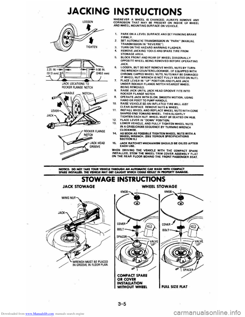
Downloaded from www.Manualslib.com manuals search engine JACKING INSTRUCTIONS
JACl LOCATIONS TO RQCI(ER FLANGE NOTCH
~
OCKER FlANGE N
JACI(HEAD , GROOve
~
WHENEVER A WHEEL IS CHA~GED. ALWAYS REMOVE ANY CQRROSIOH THAT MAY 8f !'RUENT ON INSID( OF WHEEL ANO WHEEL MOUNTING StJAFACE ON VEHIClE_
1. PARK ON A lEVEL SURFACE AND SET PARKING IIR AKE FIRMLY.
SET AUTOMATIC TRANSMISSION IN "PARK" (MANUAL TRANSMISSION IN ·'ReVERSE"I. J. TURN ON THE HAlARO WARNING FLASHER 4. REMOVE JACKING TOOLS AND SPARE TIRE FROM
STOWAGE AREA. 6. BLOCK FRONT AND REAR OF WHEEL DIAGONALLY OPPOSITE WHEEL BEING REMOVED BEFORE OPERATING JACK. 6. LOOSEN,8tH DO HOT REMOVE WHEEL NUTS BY TURN . ING WRENCH COUNTERCLOCKWISE. flf EWIf'PED WITH
CHROME CAI'f'EDWHfEL NU TS , NUTS MAY BE DAMAGEO If WHEEL NUT WRENCH lS NOT FUllY SEATEDQN NUn. PLACE LEVER IN "UP~ POSITION AND PLACE JACK UNOER ROCKER FLANGE NOTCH NEA REST WHEEL BEING REMOVE D. 8. RAISE JAC!!; UNTIL JACK HEAD GROOVE FITS INTO ROCKER FLANGE NOTCH , 9. OPERATE JACK WITH SLOW , SMOOTH MOTION, USING HAND OR FOOT TO PUMP HANDLE. 10 RAISE VEHICLE SOAN INfLATED TIRE WILL JUST CLEAR SURfACE. Ri;MOVE NUTS. WHEEL 11 INSTALL WHEEL ANO Ai;PLACE WHEEL NUTS WITH CONE sttAPEO END TOWARO WHEEl. THEN SLiGHTL V TIGHTEN EACH Nl.IT. WHEEL MUST BE SEATED ON HUB.
1 2. PlACE LEVER IN "'DOWN'" P~TION. 13 . lOWER VEHICLE, ANO fULlY TIGHTEN WHEEL NUTS IN A CRISSCROSS SEOUtNCE 8Y TURNfNG WRENCH CLOC!!;WISf. . I.. AS SOON AS POSSI8U TIGHTEN WHEEL NUTS WITH A WHEEL WRIlNCH, ('fiIi TORQUIE SPECIFICATIONS SECTIONe,) 15. JACK RATCHIETMIlCHANISM SHOULD BEQILED Antill EACH USE. WHEN DRIVING THE VEHICLE WITH THE COMPACT SPARE INSTALLED, STOW THE WHUL'TRIM COVER ASSEMBLY flAT ON THE REAR FLOOR eEHINO THE FRONT PASSENGER SEAT.
STOWAGE INSTRUCTIONS
JACK STOWAGE
W(NG
WHEEL STOWAGE
'N
3-5
fUU SIZE FlAT
Page 74 of 105
Downloaded from www.Manualslib.com manuals search engine SECTION 5
SERVICE AND MAINTENANCE
Your authorized dealer has factory trained technicians and Genuine GM Parts
to service your vehicle properly_ For expert advice and quality service, see your authorized dealer.
CAUTION: As with any machine, take care when making any check, doing any maintenance, or making any repair, to avoid being injured. Some of the MATERIALS in this vehicle may also be hazardous if used, serviced, or handled improperly. Improper or incomplete service can affect the vehicle itself which may in turn result in personal
injury, or damage to the vehicle or its equipment. H you have ANY question about carrying out some service, have the work done by a skilled technician.
REPLACEMENT FASTENERS
During vehicle maintenance, any fasteners used to replace older ones must
have the same measurements and strength as those removed, whether metric or customary. (The numbers on the heads of rnetric bons and on the surfaces
of metric nuts show their strength. Customary bolts use radial lines to show
this,
while most customary nuts do not have strength markings.) Fasteners
taken from the vehicle should be saved for re-use in the same spot when
possible. Where a fastener cannot be used again, take care to choose a
replacement that matches the old one. For information and help, see your
authorized dealer.
CAUTION: This vehicle is primarily dimensioned In the metric system. Most fasteners
are metric and many are very close in dimension to well· known customary fasteners in the inch system. Mismatched or incorrect fasteners can result in damage to the vehicle or possibly personal injury.
MAINTENANCE SCHEDULE
For owner convenience, a separate folder ,has. bee" providef;1 with your vehicle which outlines the maintenance your vehicle requires. The Maintenance
Schedule folder is supplemented by this section of the Owner's Manual.
Read this publication for a full understanding of your vehicle's maintenance
needs.
If you need a replacement Maintenance Schedule, see your dealer or contact the . Consumer . Aelations Representative, . Chevrolet Central Office,
Chevrolet Motor Division, Warren, MichigarL4809ll-13t~2-550Q1 (In Canada, contact the Customer Services Representative, General MotorsoT---
Canada LId., Oshawa, Ontario, L1J 5Z6; 416/644-6624).
FUEL CAP
The fuel cap is located behind a hinged door on the right'rear fender. For your
convenience there
is a fuel cap hanger located on the filler door.
The
fuel tank filler cap has a "s£rew-on ratcheting type" feature.
• To remove -rotate cap counterclockwise to clear the inside of the filler
neck. This will allow any residual pressure to escape.
• To install - reverse this procedure and tighten cap securely until a
"ratcheting",
clicking sound is heard indicating cap is on properly.
5-1
Page 96 of 105
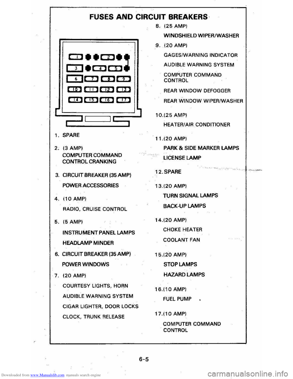
Downloaded from www.Manualslib.com manuals search engine FUSES AND CIRCUIT BREAKERS
8, 125 AMP)
r
CCl __ CD_:
OJ_COCD
CDC!J CDc::D
CD CIIl C!D r::m
em em em C!!l
,-II I~
1, SPARE
2, 13 AMPI
COMPUTER
COMMAND CONTROL CRANKING
3, CIRCUIT BREAKER (35 AMP)
POWER ACCESSORIES
4,110AMP)
RADIO, CRUISE CONTROL
5, 15 AMPI
INSTRUMENT PANEL LAMPS
HEADLAMP MINDER
6, CIRCUIT BREAKER (35 AMP)
POWER WINDOWS
7, 120 AMP)
COURTESY LIGHTS, HORN
AUDIBLE WARNING SYSTEM
CIGAR
LIGHTER, DOOR LOCKS
CLOCK,
TRUNK RELEASE
6-5
WINDSHIELD WIPER/WASHER
9, 120 AMP)
GAGES/WARNING INDICATOR
AUDIBLE WARNING SYSTEM
COMPUTER COMMAND
CONTROL
REAR WINDOW DEFOGGER
REAR WINDOW WIPER/WASHER
10,125
AMP)
HEATER/AIR
CONDITIONER
11,120 AMP)
PARK & SIDE MARKER LAMPS
LICENSE
LAMP
12,SPARE
13,120 AMP)
TURN SIGNAL LAMPS
BACK-UP LAMPS
14,120 AMP)
CHOKE HEATER
COOLANT FAN
15,(20 AMP)
STOP LAMPS
HAZARD LAMPS
16,110 AMP)
FUEL PUMP
17,110 AMP)
COMPUTER COMMAND
CONTROL