lock CHEVROLET CORVAIR 1986 2.G Owners Manual
[x] Cancel search | Manufacturer: CHEVROLET, Model Year: 1986, Model line: CORVAIR, Model: CHEVROLET CORVAIR 1986 2.GPages: 56, PDF Size: 22.23 MB
Page 6 of 56
Downloaded from www.Manualslib.com manuals search engine ..
Don't invite car theft! An unlocked car with the
key still in the ignition offers both opportunity and temptation.
Remember always to lock ignition,
lock all doors ... TAKE THE KEY!
NOTE: Your 1968 Chevrolet features as standard equipment a buzzer device which
will activate when the driver's door is opened and the key left in the switch. Heed
its
warning-let it also serve to remind you to lock all doors.
The identification number
of your vehicle is located on the instrument panel and is
visible from the outside. It is also stamped prominently on the engine and transmission.
These precautions have been taken
for your protection to aid the apprehension of thieves
and the recovery
of stolen vehicles, engines and transmissions and to serve as a deterrent
to
theft itself.
3
Page 7 of 56
Downloaded from www.Manualslib.com manuals search engine A WORD ABOUT ... VEHICLE SAFETY AND THE INI
TIAL FEDERA~ MOTOR VEHICLE SAFETY STANDARDS
Chevrolet has for many years been a leader in the field
of automotive safety. Almost every advance in design and engineering since the jnception of the industry has contributed
to the safety, reliability and durability of our cars. Continua
tion of this important and vital trend is exemplified in your
1968 Chevrolet. Important safety advances are designed to
aid in avoiding accidents, and in reducing injuries during the accident and as a result of the accident.
But remember-it takes more than a safe car to avoid
accidents. Observe all traffic laws, make safe driving a habit and maintain your car in top condition.
Your
n!,)w 1968 Chevrolet conformed to all federal motor
vehicle safety standards applicable at time of manufacture.
Effectiveness of these safety features ~an best be continued
through periodic vehicle inspection and regular maintenance .
Th~ initial Federal Motor Vehicle Safety Standards encompass a number of systems on all passenger cars. To promote better understanding of these standards, listed are those
standards applicable to passenger cars, and the purpose and
scope of each.
Initial
Federal Motor Vehicle Safety Standards (Effective January 1, 1968*)
Amendment to certain of these
Standards and additional Standards that would apply to 1968 Model passenger cars
manufactured after January 1, 1968 , were under cons ideration by the National Highway Safety Bureau at the time this Owner's Manual was prepared. '
STANDARD NO. 101
Control Location and Identification
Purpose and Scope. This standard specifies the requirements
for location and identification of certain controls to facilitate
their selection and ensure their accessibility.
4
STANDARD NO. 102 Transmission Shift Lever Sequence, Starter Interlock, and Transmission Braking Effect Purpose and Scope. This standard specifies the requirements
for the transmission shift lever sequence, a starter interlock, and for a braking effect of automatic transmissions, to requce the likelihood of shifting errors, starter engagement with vehicle in drive position, and to provide supplemental braking at speeds below 25 miles per hour.
STANDARD NO. 103 Windshield Defrosting and Defogging Purpose lind Scope. This standard specifies requirements
for providing vision through the windshield during frosting and fogging conditions.
STANDARD NO. 104 Windshield Wiping and Washing Systems
Purpose and Scope. This standard specifies requirements
for windshi eld wiping and washing systems.
ST ANDARD NO. 105 Hydraulic Service Brake, Emergency Brake, and Parking Brake Systems
Purpose and Scope. This standard specifies requirements
for hydraulic service brake, emergency brake, and parking
brake systems intended to ensure adequate braking performance under normal and emergency conditions.
STANDARD NO. 106 Hydraulic Brake Hoses Purpose and Scope. This standard specifies requirements
for hydraulic brake hoses that will reduce brake failures due to fluid leakage.
STANDARD NO. 107 Reflecting Surfaces
Purpose and Scope. This standard specifies reflecting surface requir ements for certain vehicle components in the driver's field of view.
..
Page 11 of 56
Downloaded from www.Manualslib.com manuals search engine STARTING THE ENGINE
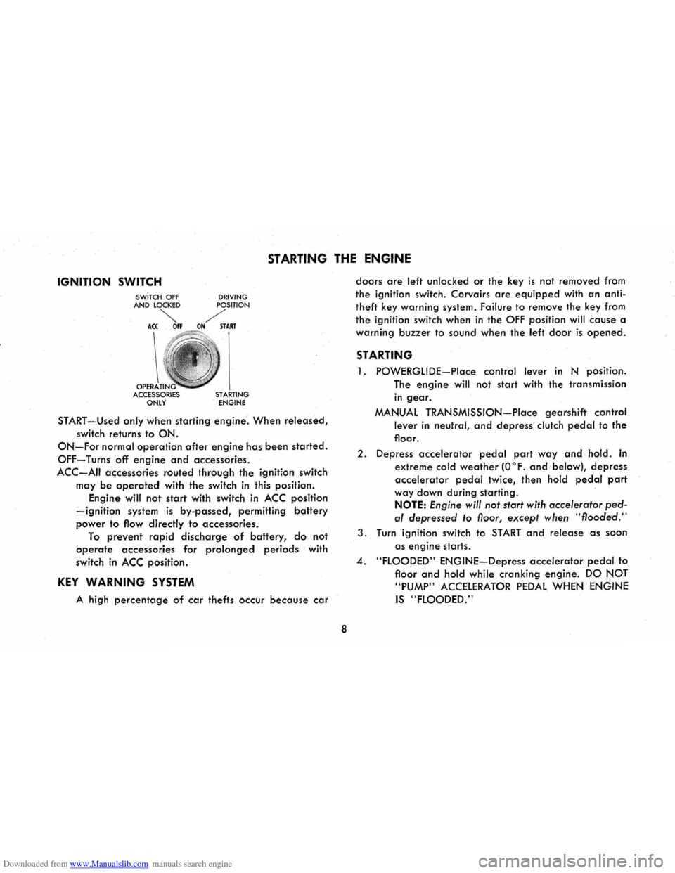
IGNITION SWITCH
OPERA ACCESSORIES ONLY DRIVING STARTING ENGINE
START-Used only when
starting engine. When released,
switch returns to ON.
ON-For normal operation after engine has been started.
OFF-Turns off engine and accessories.
ACC-AII accessories routed through the ignition switch
may
be operated with the switch in this position.
Engine will not
start with switch in ACC position
-ignition system is by-passed, permitting battery
power to flow directly to accessories.
To prevent rapid discharge of battery, do not
operate accessories for prolonged periods with
switch
in ACC position.
KEY WARNING SYSTEM
A high percentage of car thefts occur because car
8
doors are left unlocked or the key is not removed from
the ignition switch. Corvairs
are equipped with an anti
theft key warning system. Failure
to remove the key from
the ignition switch when
in the OFF position will cause a
warning
buzzer to sound when the left door is opened.
STARTING
1. POWERGLIDE-Place control lever in N position.
The
engine will not start with the transmission
in gear.
MANUAL TRANSMISSION-Place gearshift control
lever in neutral, and depress clutch pedal to the
floor.
2. Depress accelerator pedal part way and hold. In
extreme cold weather (O°F. and below), depress
accelerator pedal twice, then hold pedal part
way down during starting .
NOTE: Engine will not start with accelerator ped
al depressed to floor, except when "flooded."
3. Turn ignition switch to START and release as soon
as
engine starts .
4. "FLOODED" ENGINE-Depress accelerator pedal to
floor
and hold while cranking engine. DO NOT
"PUMP"
ACCELERATOR PEDAL WHEN ENGINE
IS "FLOODED."
Page 13 of 56
Downloaded from www.Manualslib.com manuals search engine fully synchronized, may be downshifted into first
gear at any speed below 20 mph.
TO STOP-Release the accelerator and depress the
brake pedal. As car slows down, depress the clutch
pedal and move the gearshift lever into neutral.
NEUTRAL-For use when starting or idling engine.
REVERSE-Operate as for 1 st gear but always at a
slow speed.
CAUTION: When parking or leaving the car unattended,
even for a few minutes, remove the ignition key, place
the selector lever in first gear or reverse if manual trans
mission, and fully apply the parking brake.
DRIVING WITH THE POWERGLIDE TRANSMISSION
The optional Powerglide transmission is a completely
automatic transmission which replaces the standard clutch
and transmission. After starting the engine with the se
lector lever
in N (neutral) position, merely select the
range desired and depress the accelerator. The Power
glide
transmission will do the rest.
Automatic transmission shift
quadrants of all GM
cars continue the uniform sequence of selector positions.
This particularly benefits multicar families and those who
occasionally drive other cars. Shift indicators are ar
ranged as follows: "Reverse", "Neutral" and the forward
driving
ranges. All automatic transmissions are equipped
with a starter interlock system designed to permit start
ing the engine only when the transmission selector is in
the "Neutral" position. For additional engine braking
effect,
as sometimes needed in mountainous driving,
place the transmission in an intermediate or low range.
10
The dash-mounted driving range selector is equipped
with mechanical stops to prevent unintentional shifting
into reverse
and low ranges. Move lever to the left, to
override stop,
and continue shift for selection of reverse
or low ranges.
With
lever in 0 position the transmission starts in
automatic low gear and will shift to cruising gear at
some point between approximately 12 and 50 mph,
depending on the accelerator position. Thus, a slow start
with a steady, gradual increase of pressure on the accel
erator pedal will enable the transmission to shift into the
more economical cruising gear in the shortest possible
time. Hard acceleration for fast starts will cause the trans
mission to remain in low gear for a considerably longer
period.
When driving at speeds below 45 mph, the transmis-
Page 19 of 56
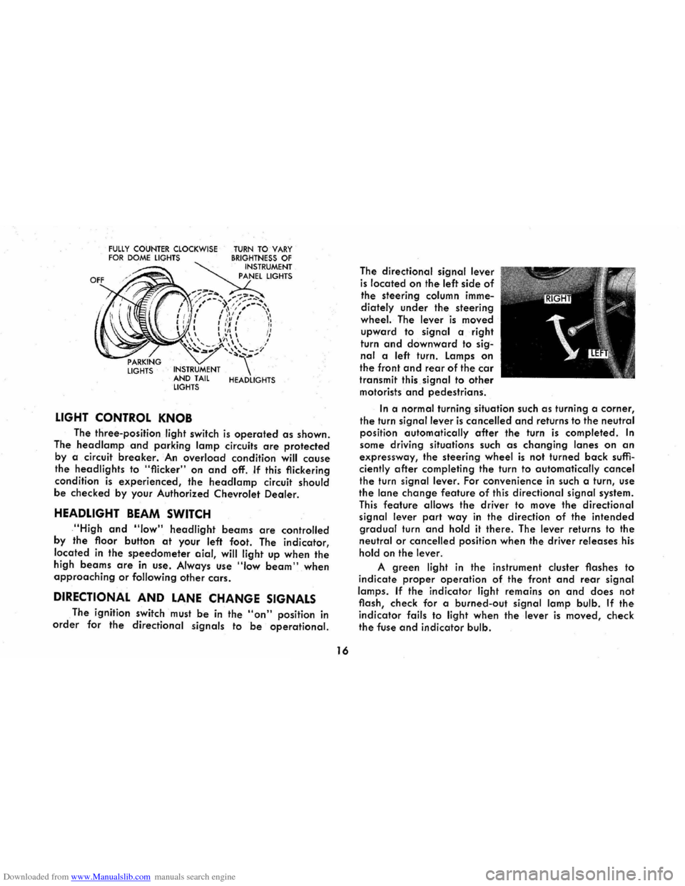
Downloaded from www.Manualslib.com manuals search engine FULLY COUNTER CLOCKWISE FOR DOME LIGHTS
LIGHTS INSTRUMENT
AND TAIL
LIGHTS
LIGHT CONTROL KNOB
TURN TO VARY BRIGHTNESS OF INSTRUMENT
PANEL LIGHTS
HEADLIGHTS
The three-position light switch is operated as shown.
The
head lamp and parking lamp circuits are protected
by a circuit breaker. An overload condition will cause
the headlights to "flicker" on and off. If this flickering
condition
is experienced, the headlamp circuit should
be checked by your Authorized Chevrolet Dealer.
HEADLIGHT BEAM SWITCH
,"High and "low" headlight beams are controlled
by
the floor button at your left foot. The indicator,
located
in the speedometer aial, will light up when the
high beams are in use . Always use "Iow beam" when approaching or following other cars.
DIRECTIONAL AND LANE CHANGE SIGNALS
The ignition switch must be in the "on" position in
order for the directional signals to be operational.
16
The directional signal lever
is located on the left side of
the steering column imme
diately
under the steering
wheel. The lever is moved
upward to signal a right
turn
and downward to sig
nal a left turn. Lamps on
the front and rear of the car
transmit this signal to other
motorists and pedestrians.
In a normal turning situation such as turning a corner,
the turn signal lever is cancelled and returns to the neutral
position automatically
after the turn is completed. In
some driving situations such as changing lanes on an
expressway, the steering wheel is not turned back suffi
ciently after completing the turn to automatically cancel
the turn signal lever. For convenience in such a turn, use
the lane change feature of this directional signal system.
This feature allows the driver to move the directional
signal lever
part way in the direction of the intended
gradual turn and hold it there. The lever returns to the
neutral or cancelled position when the driver releases his
hold on the lever.
A green light in the instrument cluster flashes to
indicate
proper operation of the front and rear signal
lamps.
If the indicator light remains on and does not
flash, check for a burned-out
signal lamp bulb. If the
indicator fails to light when the lever is moved, check
the fuse and indicator bulb.
Page 25 of 56
Downloaded from www.Manualslib.com manuals search engine AIR VENTS
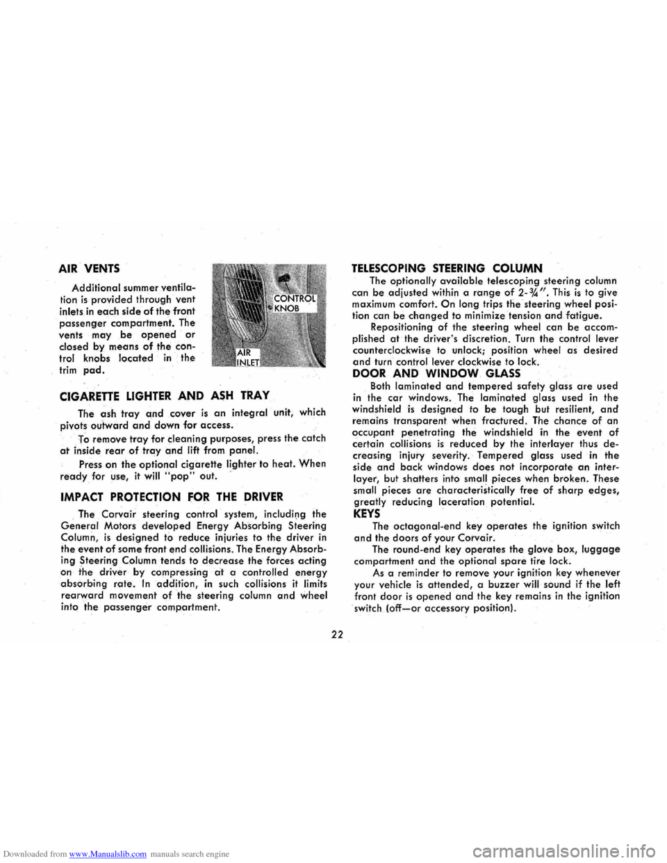
Additional summer ventila
tion is provided through vent
inlets in each side of the front
passenger compartment. The
vents
may be opened or
closed by means of the con
trol knobs located in the
trim pad.
CIGARETTE LIGHTER AND ASH TRAY
The ash tray and cover is an integral unit, which
pivots
outward and down for access.
To
remove tray for cleaning purposes, press the catch
at inside rear of tray and lift from panel.
Press on the optional cigarette lighter to heat. When
ready for use, it will "pop" out. '
IMPACT PROTECTION FOR THE DRIVER
. The Corvair steering control system, includil)g the
General Motors developed Energy Absorbing Steering
Column,
is designed to reduce injuries to the driver in
the event
of some front end collisions. The Energy Absorb
ing Steering Column tends to decrease the forces acting
on the driver by compressing at a controlled energy
absorbing rate. In addition, in such collisions it limits
rearward movement of the steering column and wheel
into the passenger compartment.
22
TELESCOPING STEERING COLUMN
The optionally available telescoping steering column
can be adjusted
within a range of 2-%". This is to give maximum comfort. On long trips the steering wheel posi
tion can
be changed to minimize tension and fatigue. Repositioning of the steering wheel can be accom
plished
at the driver's discretion. Turn the control lever
counterclockwise to unlock; position wheel as desired
and turn control lever clockwise to lock.
DOOR AND WINDOW GLASS
Both laminated and tempered safety glass are used
in the
car windows. The laminated glass used in the windshield is designed to be tough but resilient, and
remains transparent when fractured. The chance of an
occupant penetrating the windshield in the event of
certain collisions is reduced by the interlayer thus de
creasing injury severity. Tempered glass used in the
side
and back windows does not incorporate an inter
layer, but shatters into small pieces when broken. These
small pieces
are characteristically free of sharp edges,
greatly reducing laceration potential.
KEYS
The octagonal-end key operates the ignition switch
and the doors of your Corvair.
The round-end key operates the glove box, luggage
compartment and the optional spare tire lock.
As a
reminder to remove your ignition key whenever
your vehicle is attended, a buzzer will sound if the left
front door is opened and the key remains in the ignition
switch (off-or accessory position).
Page 26 of 56
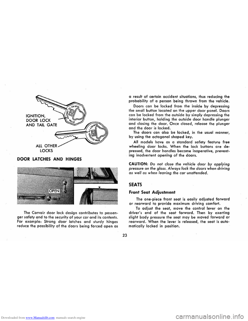
Downloaded from www.Manualslib.com manuals search engine IGNITION, DOOR
LOCK
AND TAIL GATE
ALL OTHER
LOCKS
DOOR LATCHES AND HINGES
The Corvair door lock design contributes to passen
ger safety and to the security of your car and its contents.
For
example: Strong door latches and sturdy hinges
reduce the possibility of the doors being forced open as
23
a result of certain accident situations, thus reducing the
probability
of a person being thrown from the vehicle.
Doors
can be locked from the inside by depressing
the small button located on the upper door panel. Doors
can be locked from the outside by simply depressing the
interior button, holding the outside door handle plunger
and closing the door. Once closed, release the plunger
and the door is locked.
The doors
can also be locked, in the usual manner,
by using
the octagonal shaped key.
All models have as a standard safety feature free
wheeling door locks. When the lock buttons are de
pressed, the door handles become inoperative, prevent
ing
inadvertent opening of the doors.
CAUTION: Do not close the vehicle door by applying
pressure
on the glass. Always lock the doors when driving
as well as when leaving the car unattended.
SEATS
Front Seat Adjustment
The one-piece front seat is easily adjusted forward
or rearward to provide maximum driving comfort.
To adjust the seat, move the control lever on the
driver's end of the seat forward. Then by exerting
slight
body pressure the seat may be moved forward' or
rearward. When the lever is released, the seat is auto
matically locked
in position.
Page 27 of 56
Downloaded from www.Manualslib.com manuals search engine The bucket seats are adjusted in exactly the same
manner. The seat control lever
for each seat is located
beneath the outer edge of the seat (toward the door).
Underneath the seat trim are strong steel seat struc
tures,
anchored firmly to the body. The seats and
anchorages are strong enough to prevent deformation
during low-speed impacts, but are designed in such a way that they absorb some energy by yielding to a de
gree during certain more severe higher-speed impacts.
Seat Back Lock
Folding seat backs are equipped with seH-latching
mechanisms
and release controls designed for the con
venience of entering and exiting passengers.
The release
knob is located at the lower rear of
each backrest nearest the door. lift the knob upward,
then push the seatback forward. The lock will latch
when the
seatback returns to its upright position.
OCCUPANT RESTRAINT BELTS
Suitable occupant restraints are available on all 1968
Corvairs. Worn properly, lap and shoulder belts reduce
the chances
of death or serious injury in the event of cert.ain types of accidents. Get into the habit of using
these restraints,
and using them properly, every single
time you
enter your car. Insist that your passengers use
them,
too. * By using them correctly, you give the belts
a chance
to help prevent injuries and perhaps even
save a
life.
·Shoulder belts should not be worn by persons less thon approximately 55 inches in height.
24
Lap Belts
Lap belts provide added security and comfort for
you and your passengers . Lap belts are standard equip
ment for all seating positions on all models. Proper use
and care of these belts will assure continuance of this
security.
After the front seat has been adjusted to the satis
faction of the driver, grasp the buckle end and the flat
metal "eye" end of your individual belt assembly and
position the belt across the pelvic area as LOW ON THE
PELVIS AS POSSIBLE. Insert the metal eye into the open
end of the buckle until an audible snap is heard. Make
sure the connection is secure and adjust the belt to a
SNUG FIT by pulling on the end of the belt protruding
from the buckle . The snug and low positions are essential
in
order that the force exerted by the lap belt in a colli
sion may be spread over the strong pelvic bone and not
across the soft abdominal area. For retractor equipped
belts, pull retractor half of the belts to a solid stop to
make sure that the belt webbing is completely unwound
from the retractor drum, then connect the belt and make
the necessary adjustments
at the buckle for proper fit. To
release the belts, simply depress the release
tab or button
located on the center of the buckle.
CAUTION: Never use the same belt for more than one
person at a time. Be sure to avoid: (aJ wearing a lap belt
loosely or with slack
in the system; and (bJ wearing the
belt with the
webbing wound around the retractor drum.
Page 30 of 56
Downloaded from www.Manualslib.com manuals search engine deflect or collapse under certain impacts. The soft vinyl
cover over the mirror support base further protects the occupants.
CAUTION: It is important that the driver check the
mirrors
for proper positioning, and that he make frequent
use of the mirrors to be constantly aware of the rearward
aspect
of his total driving situation.
The windshield wiper arms and blades, inside wind
shield moldings,
horn and steering wheel ornamentation,
inside rearview mirror frame and mounting bracket
incorporate low-gloss finishes. This reduces annoying
glare in the driver's forward field of view and provides
a
safer, more comfortable driving environment.
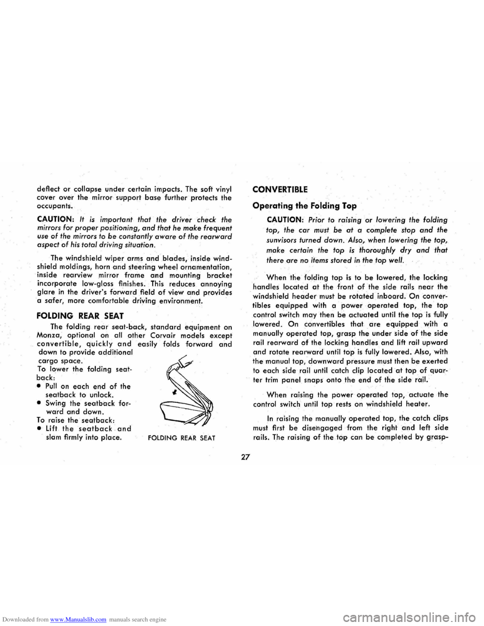
FOLDING REAR SEAT
The folding rear seat-back, standard equipment on
Monza,
optional on all other Corvair models except
convertible, quickly and easily folds forward and down to provide additional
cargo space.
To lower the folding seat
back:
• Pull on each end of the seatback to unlock.
• Swing
the seatback forward and down.
To raise the seatback:
• Lift the seat back and slam firmly into place. FOLDING REAR SEAT
27
CONVERTIBLE
Operating the Folding Top
CAUTION: Prior to raising or lowering the folding
top, the
car must be at a complete stop and the
sunvisors turned down. Also, when lowering the top,
make certain the top is thoroughly dry and that
there are
no items stored in the top well.
When the folding top is to be lowered, the locking
handles located at the front of the side rails near the
windshield header must be rotated inboard. On conver
tibles
equipped with a power operated top, the top
control switch may then be actuated until the top is fully
lowered.
On convertibles that are equipped with a
manually operated top, grasp the under side of the side
rail rearward of the locking handles and lift rail upward
and rotate rearward until top is fully lowered. Also, with
the manual top, downward pressure must then be exerted
to each side rail until catch clip located at top of quar
ter trim panel snaps onto the e.nd of the side rail.
When raising the power operated top, actuate the
control switch until top rests on windshield heater.
In raising the manually operated top, the catch clips
must first
be disehgaged from the right and left side
rails. The raising of the top can be completed by grasp-
Page 31 of 56
Downloaded from www.Manualslib.com manuals search engine ing the front corner of the top and rotating the top for
ward until top rests on windshield header.
The locking handles are then rotated outboard
which engages the lock hooks to the striker assembly
located on the windshield header.
Installing the Top Boot
Remove top boot from its protective case, which is normally stored in the luggage compartment.
Grasping forward
end of the boot, slide the welt on
the
boot into the retainer located on the top of the rear
seat back panel. The boot can then be placed over the
lowered top and the metal snap fasteners on the boot
can be snapped onto the studs on the belt molding and quarter trim. Any wrinkles that may exist may be re
lieved
by sliding the forward portion of the boot to the
right or left in the retainer.
Care of Folding Top and Rear Window
The folding top should never be subiected to vola
tile cleaners or household bleaches. Frequent washing
with
neutral soap suds, lukewarm water and soft bristle
brush
is normally all that is necessary to maintain the
"Factory Fresh" look. In the event heavy soilage or
stubborn stains are encountered, a mild foaming cleanser, lukewarm water, and a soft bristle brush may be
used. If desired, the top may be supported from the
underside during the cleaning
operation. Regardless
which cleaning method is used, a generous amount of
28
rinse water is to be used as any soap that runs down
on the
body finish and allowed to dry, may cause streaks.
After cleaning,
always be sure the top is thoroughly dry before it is lowered.
The pliable plastic window, due to its texture, is sus
ceptible
to scratches and abrasions. As a result, the top
should not be lowered when the rear window is dirty.
When cleaning the
rear window, do not use a dry
cloth or volatile cleaning agents. A soft cloth moistened
with
water should be used to remove superficial dust.
When completely washing the rear window, cold or
luke warm water and a mild neutral soap suds may be
used along with a generous amount of rinse water. In
addition, the rear window can be cleaned with G.M. Plastic Cleaner available at your dealer.
A scraper should never be used for removing snow
or ice from the rear window. In an emergency, warm
water may be cautiously used.
NOTE: DO NOT paste any stickers or masking tape
on rear window as damage will result.
ENGINE COMPARTMENT
• To open: Push up the lid release while lifting the lid.
Lift the lid all the way up, then release.
• To close: Lift up on lid, unlock the support arm catch
lock, then lower the lid. Drop the lid the last six