transmission fluid CHEVROLET CORVAIR 1986 2.G Owners Manual
[x] Cancel search | Manufacturer: CHEVROLET, Model Year: 1986, Model line: CORVAIR, Model: CHEVROLET CORVAIR 1986 2.GPages: 56, PDF Size: 22.23 MB
Page 7 of 56

Downloaded from www.Manualslib.com manuals search engine A WORD ABOUT ... VEHICLE SAFETY AND THE INI
TIAL FEDERA~ MOTOR VEHICLE SAFETY STANDARDS
Chevrolet has for many years been a leader in the field
of automotive safety. Almost every advance in design and engineering since the jnception of the industry has contributed
to the safety, reliability and durability of our cars. Continua
tion of this important and vital trend is exemplified in your
1968 Chevrolet. Important safety advances are designed to
aid in avoiding accidents, and in reducing injuries during the accident and as a result of the accident.
But remember-it takes more than a safe car to avoid
accidents. Observe all traffic laws, make safe driving a habit and maintain your car in top condition.
Your
n!,)w 1968 Chevrolet conformed to all federal motor
vehicle safety standards applicable at time of manufacture.
Effectiveness of these safety features ~an best be continued
through periodic vehicle inspection and regular maintenance .
Th~ initial Federal Motor Vehicle Safety Standards encompass a number of systems on all passenger cars. To promote better understanding of these standards, listed are those
standards applicable to passenger cars, and the purpose and
scope of each.
Initial
Federal Motor Vehicle Safety Standards (Effective January 1, 1968*)
Amendment to certain of these
Standards and additional Standards that would apply to 1968 Model passenger cars
manufactured after January 1, 1968 , were under cons ideration by the National Highway Safety Bureau at the time this Owner's Manual was prepared. '
STANDARD NO. 101
Control Location and Identification
Purpose and Scope. This standard specifies the requirements
for location and identification of certain controls to facilitate
their selection and ensure their accessibility.
4
STANDARD NO. 102 Transmission Shift Lever Sequence, Starter Interlock, and Transmission Braking Effect Purpose and Scope. This standard specifies the requirements
for the transmission shift lever sequence, a starter interlock, and for a braking effect of automatic transmissions, to requce the likelihood of shifting errors, starter engagement with vehicle in drive position, and to provide supplemental braking at speeds below 25 miles per hour.
STANDARD NO. 103 Windshield Defrosting and Defogging Purpose lind Scope. This standard specifies requirements
for providing vision through the windshield during frosting and fogging conditions.
STANDARD NO. 104 Windshield Wiping and Washing Systems
Purpose and Scope. This standard specifies requirements
for windshi eld wiping and washing systems.
ST ANDARD NO. 105 Hydraulic Service Brake, Emergency Brake, and Parking Brake Systems
Purpose and Scope. This standard specifies requirements
for hydraulic service brake, emergency brake, and parking
brake systems intended to ensure adequate braking performance under normal and emergency conditions.
STANDARD NO. 106 Hydraulic Brake Hoses Purpose and Scope. This standard specifies requirements
for hydraulic brake hoses that will reduce brake failures due to fluid leakage.
STANDARD NO. 107 Reflecting Surfaces
Purpose and Scope. This standard specifies reflecting surface requir ements for certain vehicle components in the driver's field of view.
..
Page 20 of 56

Downloaded from www.Manualslib.com manuals search engine If the system is not functioning properly, a legal hand
signal should be given, since failure to indicate a turn
is considered a moving traffic violation in many states.
Always signal for a turn
at a reasonable distance before actu 'ally making it.
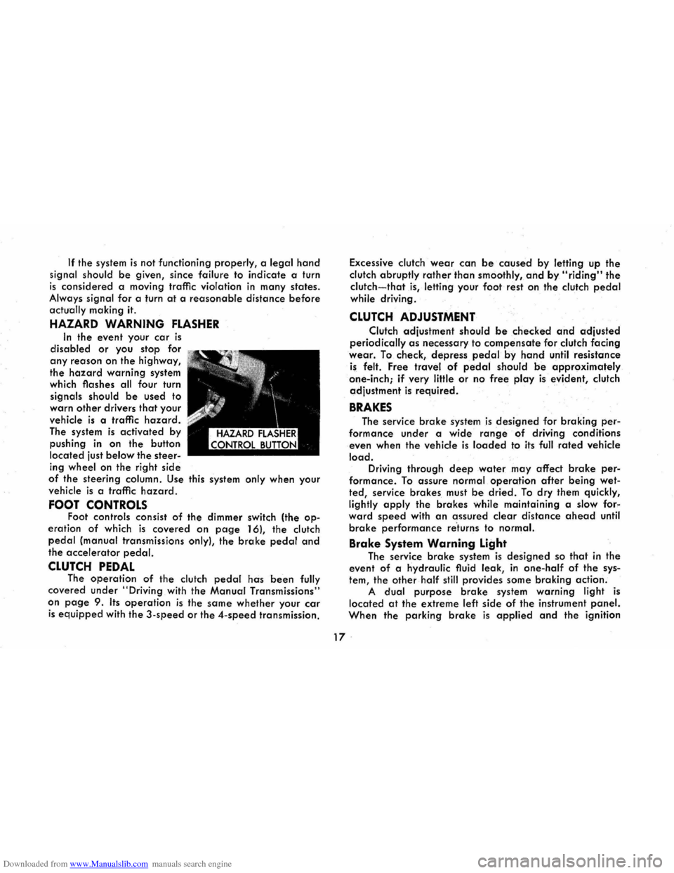
HAZARD WARNING FLASHER
In the event your car is
disabled or you stop for
any reason on the highway,
the
hazard warning system
which flashes all four turn
signals should
be used to
warn
other drivers that your
vehicle
is a traffic hazard.
The system is activated by
pushing
in on the button
located just
below the steer
ing wheel on the right side
of the steering column. Use this system only when your
vehicle
is a traffic hazard.
FOOT CONTROLS Foot controls consist of the dimmer switch (the op
eration of which is covered on page 16), the clutch
pedal (manual transmissions only), the brake pedal and
the accelerator pedal.
CLUTCH PEDAL The operation of the clutch pedal has been fully
covered under
"Driving with the Manual Transmissions"
on
page 9. Its operation is the same whether your car
is equipped with the 3-speed or the 4-speed transmission. Excessive
clutch
wear can be caused by letting up the
clutch abruptly
rather than smoothly, and by "riding" the
clutch-that is, letting your foot rest on the clutch pedal
while driving .
CLUTCH ADJUSTMENT
Clutch adjustment should be checked and adjusted
periodically as necessary to compensate for clutch facing
wear. To check, depress pedal.by hand until resistance
is felt. Free travel of pedal should be approximately
one-inch;
if very little or no free play is evident, clutch
adjustment
is required.
BRAKES
The service brake system is designed for braking per
formance under a wide range of driving conditions
even when the vehicle
is loaded to its full rated vehicle
load. Driving through deep water may affect brake per
formance. To assure normal operation after being wet
ted, service brakes must be dried. To dry them quickly,
lightly
apply the brakes while maintaining a slow for"
ward speed with an assured clear distance ahead until
brake performance re'turns to normal.
Brake System Warning Light
The service brake system is designed so that in the
event of a hydraulic fluid leak,
in one-half of the sys
tem, the other half still provides some braking action.
A dual purpose brake system warning light is
located at the extreme left side of the instrument panel.
When the parking brake is applied and the ignition
17 .
Page 43 of 56

Downloaded from www.Manualslib.com manuals search engine TRANSMISSION CONTROL LlNKAGE-
3 AND 4-SPEED
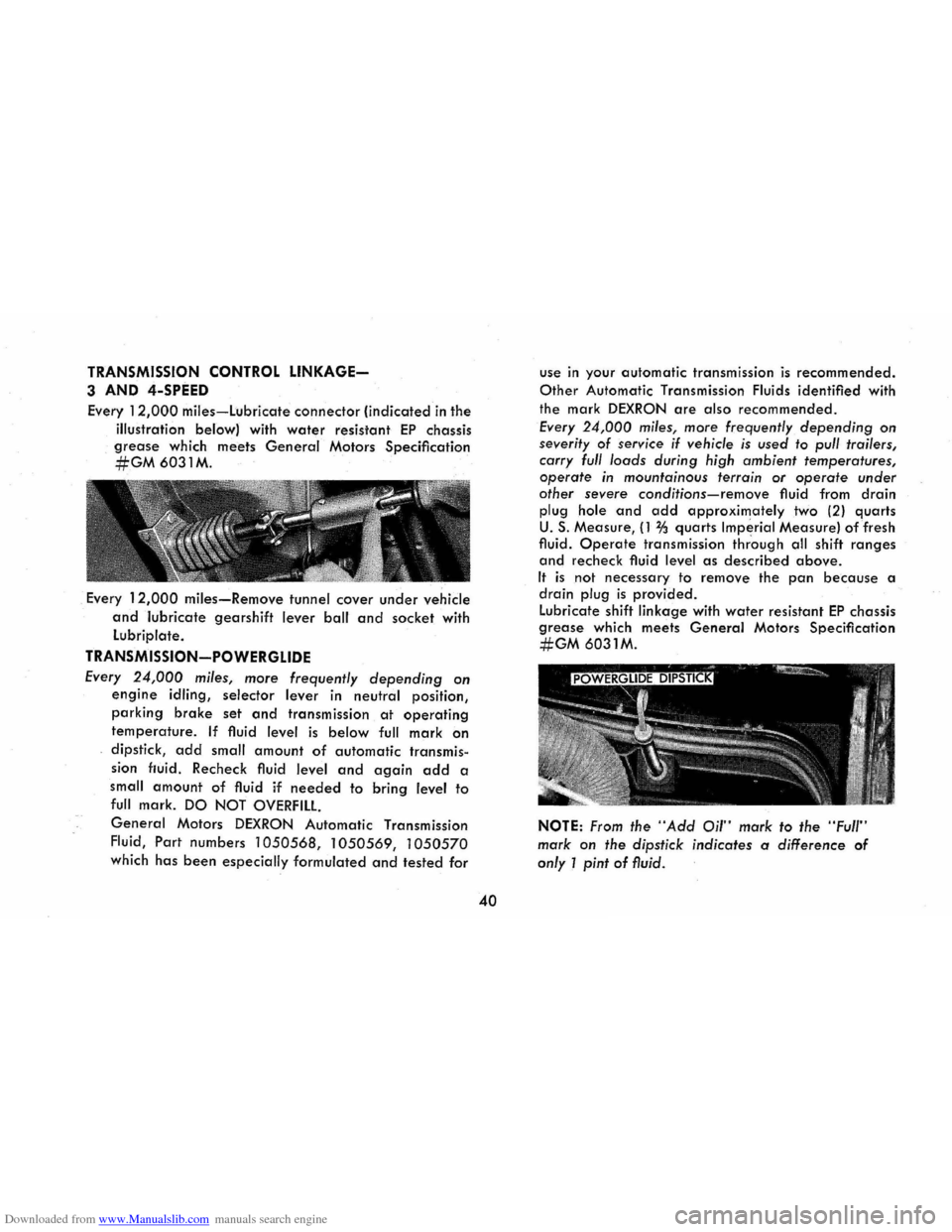
Every 12,000 miles-Lubricate connector (indicated in the
illustration below) with
water resistant EP chassis
grease which meets General Motors Specification
#GM6031M.
. Every 12,000 miles-Remove tunnel cover under vehicle
and lubricate gearshift lever ball and socket with
Lubriplate.
TRANSMISSION-POWERGLIDE
Every 24,000 miles, more frequently depending on
engine idling, selector lever in neutral position,
parking brake set and transmission at operating
temperature. If fluid level is below full mark on
dipstick, add small amount of automatic transmis
sion fluid. Recheck fluid level and again add a
small
amount of fluid if needed to bring level to
full mark. DO NOT OVERFILL
General Motors DEXRON Automatic Transmission
Fluid,
Part numbers 1050568, 1050569, 1050570
which has been especially formulated and tested for
40
use in your automatic transmission is recommended.
Other Automatic Transmission Fluids identified with
the mark
DEXRON are also recommended.
Every 24,000 miles, more frequently depending on
severity of service if vehicle is used to pull trailers,
carry full loads during high ambient temperatures,
operate in mountainous terrain or operate under
other severe
conditions-remove fluid from drain
plug hole and add approximately two (2) quarts
U. S. Measure, (1 % quarts Imperial Measure) of fresh
fluid.
Operate transmission thr'ough all shift ranges
and recheck fluid level as described above.
It is not necessary to remove the pan because a
drain plug is provided .
Lubricate shift linkage with
water resistant EP chassis
grease which meets General Motors Specification
#GM 6031M.
NOTE: From the "Add Oil" mark to the "Full"
mark on the dipstick indicates a difference of
only 1 pint of fluid.