window CHEVROLET CORVAIR 1986 2.G Owners Manual
[x] Cancel search | Manufacturer: CHEVROLET, Model Year: 1986, Model line: CORVAIR, Model: CHEVROLET CORVAIR 1986 2.GPages: 56, PDF Size: 22.23 MB
Page 8 of 56
Downloaded from www.Manualslib.com manuals search engine STANDARD NO. III Rearview Mirrors
Purpose and Scope. This standard specifies requirements for
rearview mirrors to provide the driver with a clear and rea
sonably unobstmcted view to the rear.
STANDARD NO. 203 Impact Protection for the Driver From the Steering Control System Purpose and Scope. This standard specifies requirements for
steering control systems that will minimize chest, neck, and facial injuries to the driver as a result of impact.
STANDARD NO. 204
Steering Control Rearward Displacement
Purpose and Scope. This standard specifies requirements
limiting the rearward displacement of the steering control
into the passenger compartment to reduce the likelihood of chest, neck, or head injury.
STANDARD NO. 205 Glazing Materials
Purpose and Scope. This standard specifies requirements
for glazing materials to reduce lacerations to the face, scalp, and neck, and to minimize the possibility of occupants being
thrown through the vehicle windows in collisions.
STANDARD NO. 206 Door Latches and Door Hinge Systems Purpose and Scope. This standard specifies load require
m ents for door latches and door hinge systems to minimize
the probability of occupants being thrown from the vehicle
in a collision.
STANDARD NO. 207 Anchorage of Seats Purpose and Scope. This standard establishes requirements
for seats, their attachment assemblies, and their installation
to minimize the possibility of failure by forces acting on the seat as a result of vehicle impact.
5
STANDARD NO. 208
Seat Belt Installations
Purpose and Scope. This standard establishes requirements
for seat belt installations.
STANDARD NO. 2090
Seat Belt Assemblies
Purpose and Scope. This standard specifies requirements
for seat belt assemblies.
STANDARD NO. 210
S ea t Belt Assembly Anchorages
Purpose and Scope. This standard specifies the requirements
for seat belt assembly anchorages to ensure proper location
for effective occupant restraint and reduce the likelihood
of failure in collisions.
STANDARD NO. 211
Wheel Nuts, Wheel Discs, and Hub Caps
Purpose and Scope. This standard precludes the use of wheel nuts, wheel discs, and hub caps that constitute a hazard to
pedestrians and cyclists .
STANDARD NO. 301 Fuel Tanks, Fuel Tank Filler Pipes, and Fuel Tank Con-
nections
Purpose
and Scope. This standard specifies requirements
for the integrity and security of fuel tanks, fuel tank filler
pipes, and fuel tank connections to minimize fire hazard as
a result of collision.
PUBLIC LAW 87·637 (1962) * An Act to provide that hydraulic brake fluid sold or shipped in commerce for use in motor vehicles shall meet cer
tain specifications prescribed by the Secretary of Commerce. The requirements of this law were issued as standards when the National Traffic and Motor Vehicle Safety Act of 1966
was enacted.
"The Sea t (Lap) Belt and Brak e fluid standards are applicable
to all 1968 models of affected vehicles.
Page 23 of 56
Downloaded from www.Manualslib.com manuals search engine • MAXIMUM HEAT REQUIREMENTS-Depress HEAT lever
to extreme down position.
If heat becomes exces
sive, pull up HEAT knob to desired position.
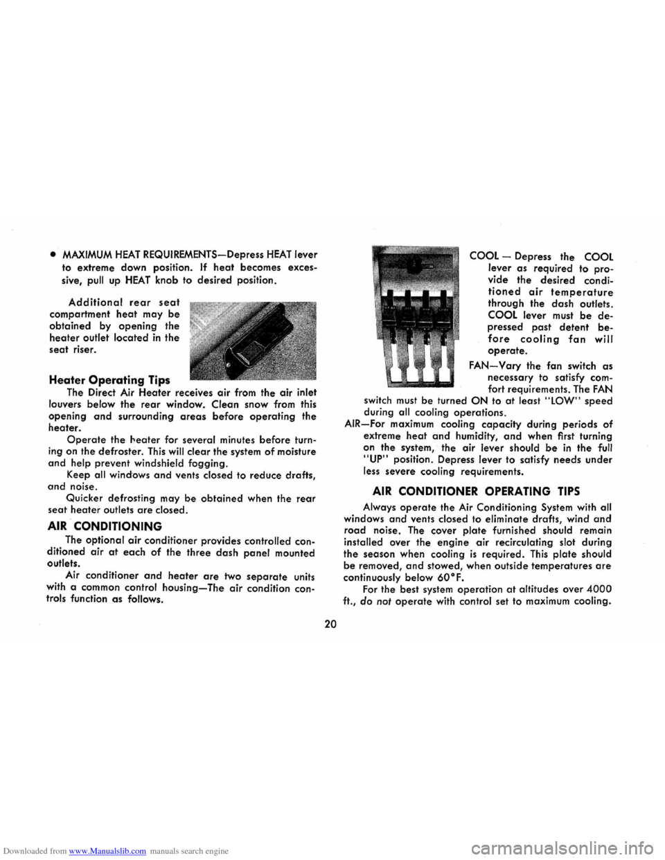
Additional rear seat
compartment heat may be
obtained by opening the
heater outlet located in the
seat riser.
Heater Operating Tips
The Direct Air Heater receives air from the air inlet
louvers below the
rear window. Clean snow from this
opening
and surrounding areas before operating the
heater.
Operate the heater for several minutes before turn
ing on the defroster. This will clear the system of moisture
and help prevent windshield fogging.
Keep
all windows and vents closed to reduce drafts,
and noise.
Quicker defrosting may
be obtained when the rear
seat heater outlets are closed.
AIR CONDITIONING
The optional air conditioner provides controlled con
ditioned air at each of the three dash panel mounted
outlets.
Air conditioner
and heater are two separate units
with a common control
housing-The air condition controls function as follows.
20
COOL -Depress the COOL
lever as required to pro
vide the desired condi
tioned air temperature
through the dash outlets.
COOL lever must be de
pressed past detent be
fore cooling fan will
operate.
FAN-Vary the fan switch as
necessary to satisfy com
fort requirements. The FAN
switch must be turned ON to at least "lOW" speed
during all cooling operations.
AIR-For maximum cooling capacity during periods of
extreme heat and humidity, and when first turning
on the system, the air lever should
be in the full
"UP" position. Depress lever to satisfy needs under
less
severe cooling requirements.
AIR CONDITIONER OPERATING TIPS
Always operate the Air Conditioning System with all
windows
and vents closed to eliminate drafts, wind and
road noise. The cover plate furnished should remain
installed over the engine air recirculating slot during
the season when cooling
is required. This plate should
be removed, and stowed, when outside temperatures are
continuously below 60°F.
For the best system operation at altitudes over 4000
ft., do not operate with control set to maximum cooling.
Page 25 of 56
Downloaded from www.Manualslib.com manuals search engine AIR VENTS
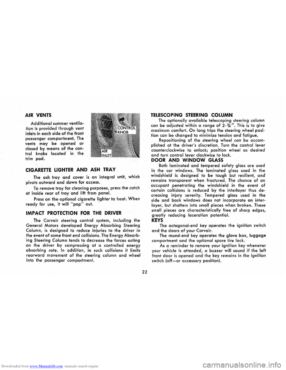
Additional summer ventila
tion is provided through vent
inlets in each side of the front
passenger compartment. The
vents
may be opened or
closed by means of the con
trol knobs located in the
trim pad.
CIGARETTE LIGHTER AND ASH TRAY
The ash tray and cover is an integral unit, which
pivots
outward and down for access.
To
remove tray for cleaning purposes, press the catch
at inside rear of tray and lift from panel.
Press on the optional cigarette lighter to heat. When
ready for use, it will "pop" out. '
IMPACT PROTECTION FOR THE DRIVER
. The Corvair steering control system, includil)g the
General Motors developed Energy Absorbing Steering
Column,
is designed to reduce injuries to the driver in
the event
of some front end collisions. The Energy Absorb
ing Steering Column tends to decrease the forces acting
on the driver by compressing at a controlled energy
absorbing rate. In addition, in such collisions it limits
rearward movement of the steering column and wheel
into the passenger compartment.
22
TELESCOPING STEERING COLUMN
The optionally available telescoping steering column
can be adjusted
within a range of 2-%". This is to give maximum comfort. On long trips the steering wheel posi
tion can
be changed to minimize tension and fatigue. Repositioning of the steering wheel can be accom
plished
at the driver's discretion. Turn the control lever
counterclockwise to unlock; position wheel as desired
and turn control lever clockwise to lock.
DOOR AND WINDOW GLASS
Both laminated and tempered safety glass are used
in the
car windows. The laminated glass used in the windshield is designed to be tough but resilient, and
remains transparent when fractured. The chance of an
occupant penetrating the windshield in the event of
certain collisions is reduced by the interlayer thus de
creasing injury severity. Tempered glass used in the
side
and back windows does not incorporate an inter
layer, but shatters into small pieces when broken. These
small pieces
are characteristically free of sharp edges,
greatly reducing laceration potential.
KEYS
The octagonal-end key operates the ignition switch
and the doors of your Corvair.
The round-end key operates the glove box, luggage
compartment and the optional spare tire lock.
As a
reminder to remove your ignition key whenever
your vehicle is attended, a buzzer will sound if the left
front door is opened and the key remains in the ignition
switch (off-or accessory position).
Page 29 of 56
Downloaded from www.Manualslib.com manuals search engine HEAD RESTRAINTS
Head restraints are available for the driver and front
right
passenger as factory installed options. They can be
adjusted to different heights by pulling up or pushing
down by
hand. Detents provide positive head restraint
location. Head restraints should be adjusted, within
limits of travel, to contact the center of the back of head
when the head is moved straight back.
CHILD RESTRAINT
Children in automobiles should be restrained. A
restraint system
designed by General Motors specifically
for
children is available from your dealer. If children
are traveling in a vehicle not equipped with this child
restraint system, the following precautions should be
taken:
1. Children should be placed in the rear seat. Never
allow a child to stand or kneel on the rear seat as
this raises his center of gravity.
2. Infants unable to sit up by themselves should be
restrained by placing them in a covered, padded
bassinet which is placed crossways on th·e rear
REARVIEW MIRRORS
Inside and outside rearview mirrors have been care
fully designed and located to give the driver a clear and
reasonably unobstructed view of the rear of the car. It
is not intended that these mirrors be used for operation
in reverse gear, or for surveillance of conditions close
to
the back of the car. It is suggested that the driver
turn his
head and look close to the back for backing
26
seat. The bassinet should be securely restrained
with the regular vehicle seat belt. An alternative
method is to position the bassinet crossways in the
vehicle so
that it rests against the back of the front seat. ..
3. When a child is old enough to sit up by himself in
a car, he should sit on a firm cushion and use the
conventional lap belt to restrain him at the pelvis.
The cushion should be as firm as practical and
enable the child to look horizontally out of the car
windows.
4. The use
of the cushion should be discontinued as
soon as the child is old enough to see out of the
car windows without it.
5. Do not use shoulder belts on children shorter than approximately 55 inches in height.
6. If a child must stand, he should stand on the floor
directly behind the front seat. This will minimize
the possibility of his being thrown from the rear
compartment during a sudden stop. However, this
method
should be used only if more complete re
straint cannot be used.
operations, and survey the area to the immediate rear
of the car prior to entering the car for the backing
operation. The outside mirror and mounting is free of
sharp points or edges that could contribute to injury of
pedestrians. The inside rearview mirror incorporates provisions
for
vertical as well as tilt adjustments to provide better
positioning for the driver. The mounting is designed to
Page 31 of 56
Downloaded from www.Manualslib.com manuals search engine ing the front corner of the top and rotating the top for
ward until top rests on windshield header.
The locking handles are then rotated outboard
which engages the lock hooks to the striker assembly
located on the windshield header.
Installing the Top Boot
Remove top boot from its protective case, which is normally stored in the luggage compartment.
Grasping forward
end of the boot, slide the welt on
the
boot into the retainer located on the top of the rear
seat back panel. The boot can then be placed over the
lowered top and the metal snap fasteners on the boot
can be snapped onto the studs on the belt molding and quarter trim. Any wrinkles that may exist may be re
lieved
by sliding the forward portion of the boot to the
right or left in the retainer.
Care of Folding Top and Rear Window
The folding top should never be subiected to vola
tile cleaners or household bleaches. Frequent washing
with
neutral soap suds, lukewarm water and soft bristle
brush
is normally all that is necessary to maintain the
"Factory Fresh" look. In the event heavy soilage or
stubborn stains are encountered, a mild foaming cleanser, lukewarm water, and a soft bristle brush may be
used. If desired, the top may be supported from the
underside during the cleaning
operation. Regardless
which cleaning method is used, a generous amount of
28
rinse water is to be used as any soap that runs down
on the
body finish and allowed to dry, may cause streaks.
After cleaning,
always be sure the top is thoroughly dry before it is lowered.
The pliable plastic window, due to its texture, is sus
ceptible
to scratches and abrasions. As a result, the top
should not be lowered when the rear window is dirty.
When cleaning the
rear window, do not use a dry
cloth or volatile cleaning agents. A soft cloth moistened
with
water should be used to remove superficial dust.
When completely washing the rear window, cold or
luke warm water and a mild neutral soap suds may be
used along with a generous amount of rinse water. In
addition, the rear window can be cleaned with G.M. Plastic Cleaner available at your dealer.
A scraper should never be used for removing snow
or ice from the rear window. In an emergency, warm
water may be cautiously used.
NOTE: DO NOT paste any stickers or masking tape
on rear window as damage will result.
ENGINE COMPARTMENT
• To open: Push up the lid release while lifting the lid.
Lift the lid all the way up, then release.
• To close: Lift up on lid, unlock the support arm catch
lock, then lower the lid. Drop the lid the last six
Page 32 of 56
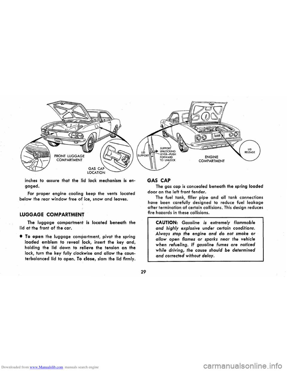
Downloaded from www.Manualslib.com manuals search engine inches to assure that the lid lock mechanism is en
gaged.
For proper engine cooling keep the vents located
below the
rear window free of ice, snow and leaves.
LUGGAGE COMPARTMENT
The luggage compartment is located beneath the
lid at the front of the car.
• To open the luggage compartment, pivot the spring
loaded emblem to reveal lock, insert the key and,
holding the lid down to r~lieve the tension on the
lock, turn the key fully clockwise
and allow the coun
terbalanced lid to open. To close, slam the lid firmly.
29
GAS CAP
ENGINE COMPARTMENT
The gas cap is concealed beneath the spring loaded
door on the left front fender.
The fuel tank, filler pipe and all tank connections
have been carefully designed to reduce fuel
leakage
after termination of certain collisions. This design reduces
fire hazards in these collisions.
CAUTION: Gasoline is extremely flammable
and highly explosive under certain conditions.
Always stop the engine
and do not smoke or
allow open flames or sparks near the vehicle
when refueling.
If gasoline fumes are noticed
while driving,
the cause should be determined
and corrected without delay.
Page 37 of 56
Downloaded from www.Manualslib.com manuals search engine level, remove the oil gauge rod (dip stick), wipe it
clean and reinsert it firmly for an accurate reading.
The oil level should be maintained in the safety margin,
neither going above the FULL line nor below the ADD
mark. Reseat the gauge firmly after taking the reading.
DO NOT OVERFilL.
COOLING SYSTEM CARE
The engine fan belt should be checked for tightness
at regular intervals. When a new belt is needed use only
the approved premium belt available from your Chev
rolet dealer. If any other belt is installed, replace with
recommended belt when possible.
Watch the TEMP-PRESS and GEN-FAN indicators on the
instrument
panel for signs of overheating.
Air inlet louvers, located in the panel below the rear
window, supply air for engine combustion and cooling
and for the Direct Air Heater. Make sure the louvers are
never sealed or blocked.
TIRES
The factory installed tires on your car are selected
to provide the best all around tire performance for all
normal operation. When inflated as recommended in
the
tire inflation pressure table they have the load
carrying capacity to operate satisfactorily at all loads
up to and including the specified full rated load, at all
normal highway speeds.
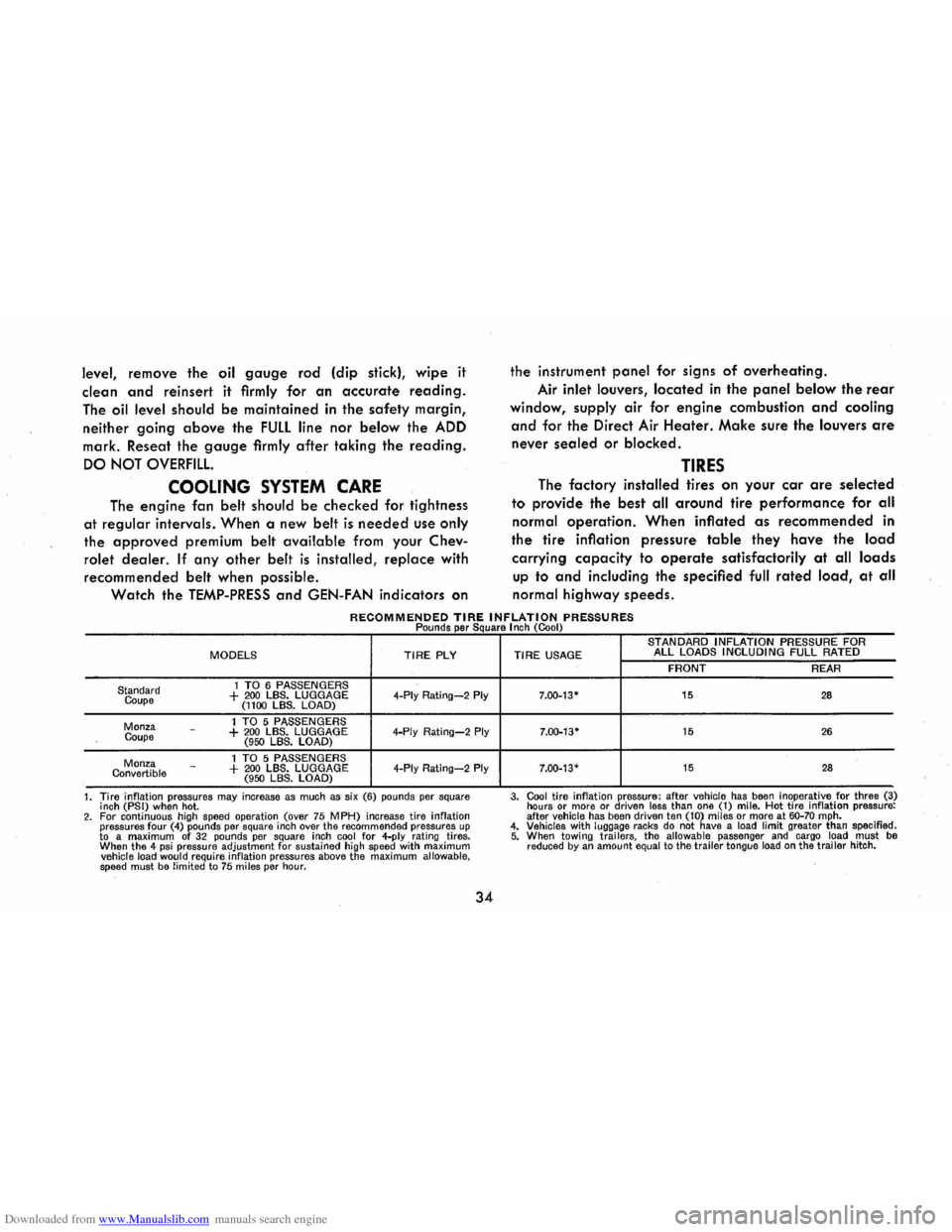
RECOMMENDED TIRE INFLATION PRESSURES Pounds per Square I nch (Cool)
MODELS TIRE PLY
1 TO 6 PASSENGERS Standard
Coupe + 200 LBS. LUGGAGE 4-Ply Rating-2 Ply (1100 LBS. LOAD)
1 TO 5 PASSENGERS Monza
Coupe -+ 200 LBS. LUGGAGE 4-Ply Rating-2 Ply (950 LBS. LOAD)
1 TO 5 PASSENGERS Monza Convertible -+ 200 LBS. LUGGAGE 4-Ply Rating-2 Ply (950 LBS. LOAD)
1. Tire inflation pressures
may increase as much as six (6) pounds per square
inch (PSI) when hot. 2. For continuous high speed operation (over 75 MPH) increase tire inflation pressures four (4) pounds per square inch over the recommended pressures up to a maximum of 32 pounds per square inch cool for 4-ply rating tires.
When the 4 psi pressure adjustment for sustained high speed with maximum vehicle load would require inflation pressures above the maximum allowable, speed must be limited to 75 miles per hour.
34
STANDARD INFLATION PRESSURE FOR TIRE USAGE ALL LOADS INCLUDING FULL RATED
FRONT REAR
7.00-13-15 28
7.00-13· 15 26
7.00-13· 15 28
3. Cool tire inflation pressure: after vehicle has been inoperative for three (3)
hours or more or driven less than one (1) mile. Hot tire inflation pressure:
after vehicle has been driven ten (10) miles or more at 60-70 mph. 4. Vehicles with luggage racks do not have a load limit greater than specified. 5. When towi ng trai lers, the allowable passenger and cargo load must be reduced by an amount equal to the trailer tongue load on the trailer hitch.