ABS CHEVROLET CORVETTE 1998 5.G Owners Manual
[x] Cancel search | Manufacturer: CHEVROLET, Model Year: 1998, Model line: CORVETTE, Model: CHEVROLET CORVETTE 1998 5.GPages: 378, PDF Size: 19.91 MB
Page 151 of 378
Downloaded from www.Manualslib.com manuals search engine ABS ACTIVE (Anti-Lock Brake System Active) - :
When your anti-lock system is adjusting brake pressure
to help avoid a braking skid, the ABS ACTIVE message
will be displayed.
Slippery road conditions may exist if this message is
displayed,
so adjust your driving accordingly. The
message will stay on for a few seconds after the system
stops adjusting brake pressure.
SERVICE ABS (Anti-Lock Brake System) - : If the
SERVICE ABS message is displayed when you
are
driving, stop as soon as possible and turn the ignition
off. Then start the engine again to reset the system. If
the message stays on, or comes back on again while you
are driving, your vehicle is in need of service. If the
regular brake system warning light isn’t on, you still
have brakes, but don’t have anti-lock brakes. If the
regular brake system light is also on, you don’t have
anti-lock brakes and there is a problem with your
brakes.
See “Brake System Warning Light” earlier in
this section.
If the SERVICE ABS message is being displayed, your
traction control system and the optional active handling system will also be disabled. The driver information
center will scroll three messages SERVICE ABS,
SERVICE TRACTION SYS. and SERVICE ACTIVE
HNDLG and the instrument cluster car icon will be illuminated.
The driver can acknowledge these messages
by pressing the reset button three times. When the
service message is displayed the computer controlled
systems will not assist the driver and you should have
the system repaired as soon as possible. Adjust your
driving accordingly.
SERVICE COLUMN LOCK: The system that
controls the locking and unlocking of the steering
column may not work properly. Have the vehicle towed
to a dealer for service.
LOW OIL PRESSURE: You will hear four chimes and
the CHECK GAGES telltale will come on when this
message is displayed.
To acknowledge the warning,
press the RESET button. After you press the
RESET
button, a message will be displayed and you will hear a
chime every minute until the vehicle is serviced.
If you
do not press RESET, the message will remain on the
digital display until the vehicle is serviced.
Low oil pressure may be the result of a combination of
low oil level and abrupt changes in the vehicle’s
direction. When this warning
is displayed, you should
not operate the engine at high
RPM or make fast abrupt
moves. When convenient, you should check the oil
level. See “Engine Oil” in the Index.
Page 154 of 378
Downloaded from www.Manualslib.com manuals search engine SERVICE RIDE CONTROL: This message is used to
indicate to the driver that the Selective Real Time
Damping (SRTD) system has detected a malfunction
and that the system must be serviced. The SERVICE
RIDE CONTROL message will always come on when a
failure is detected by the Selective Real Time Damping
system. If
a fault is present in the SRTD which causes
the shocks to be in their full soft condition, the
SERVICE RIDE CONTROL, SHOCKS
INOPERATIVE and MAXIMUM
80 MPH (129 km/h)
will display together. You will never get a SHOCKS
INOPERATIVE and MAXIMUM SPEED
80 MPH
(129
km/h) message without a SERVICE RIDE
CONTROLmessage.
SHOCKS INOPERATIVE: You will hear four chimes
when this message is displayed. To acknowledge that
you have read the message and to remove it from the
display, press RESET. The message will reappear every
10 minutes until this condition changes.
This message indicates that a malfunction is present in
the Selective Real Time Damping system which is
causing the shocks to be in their full soft mode. This is a
warning to the driver that the vehicle handling may be
affected. Have your vehicle serviced as soon as possible.
MAXIMUM SPEED 80 MPH (129 km/h): You will
hear four chimes when this message is displayed.
To
acknowledge the warning, press RESET. After you press
RESET, a message will reappear every
10 minutes until
this condition changes.
This message indicates that the vehicle speed will be limited to
80 mph (129 km/h) when the shock absorber
system has failed and the shocks are in their full
soft
mode. Have your vehicle serviced as soon as possible.
LOW COOLANT You will hear two chimes when this
message is displayed. To acknowledge the warning,
press RESET. After you press RESET, a message will
reappear and you will hear a chime every
10 minutes
until this condition changes.
This message indicates that the coolant in the system is
low. You may need to add coolant. See “Engine
Overheating” in the Index.
COOLANT OVER TEMP: You will hear four chimes
and the CHECK GAGES telltale
will come on when this
message is displayed. To acknowledge the warning,
press the RESET button. After you press the RESET
button, a message will be displayed and you will hear a chime every minute until this condition changes. If you
do not press RESET, the message will remain on the
digital display until the condition changes.
2-101
Page 165 of 378
Downloaded from www.Manualslib.com manuals search engine As the interior of the vehicle warms up to your comfort
set temperature, the fan speed will decrease and the
temperature output may become cooler.
If the interior
temperature continues to warm up due to heating from
the sun or outside temperature increases, the system
may switch to other air delivery modes (typically
DEFOG or BI-LEVEL).
A ljpical Hot Weather Example:
Your vehicle has been parked outside all day in hot
weather (above
7OoF/ 21 O C) and you have set the driver
temperature at
73 OF (23 "C) and have selected the
AUTO mode. The system will automatically adjust the
temperature output to maximum cooling. The blower
will start at a low speed momentarily to push the hot air
to the floor of the vehicle and then go to a higher blower
speed with cold airflow out of the instrument panel
outlets.
A small amount of airflow will continue through
the lower ducts to cool the
floor area.
The air intake may start in the recirculated mode for
maximum cooling performance.
As the interior of the
vehicle cools down to your comfort set temperature, the
fan speed will decrease and the temperature output may
become warmer. The air intake may shift from
recirculation to fresh air mode.
If the interior continues to
cool due to a decrease,,,in the amount of heat the
vehicle is absorbing from the sun or a decrease
in the
outside temperature, the system could switch to other air
delivery modes (typically BI-LEVEL or DEFOG).
Manual Settings
With the Dual Zone Electronic Climate Control, there
are several manual settings you can use to control the
system and override the
AUTO operation. You can
program the fan speed,
air delivery mode, air intake
mode and control the air conditioning operation using
these settings. The system will still determine the
temperature output level based on the driver-set
temperature and the passenger temperature offset.
% FAN SPEED: Press the button with the fan switch
on it to manually lock
in the current fan speed and to
stop the automatic fan speed control. Pressing the
arrows will delete
AUTO from the digital display. The
fan graphics with the fan speed bars will be shown.
To
increase the fan speed so that more air flows into the
vehicle, press the
UP arrow on the fan switch. To
decrease the fan speed and airflow, press the DOWN
arrow. The
AUTO button must be pressed to return to
the automatic fan control.
Page 168 of 378
Downloaded from www.Manualslib.com manuals search engine Sensors
The Dual Zone Electronic Climate Control System
uses several sensors to control operation and
display information.
Solar Load Sensor
This sensor is located on the top right side of the
defroster grille. The defroster grille is on the top of the
instrument panel.
The sensor monitors the sun’s solar radiation and uses
this information as
part of the automatic climate control
system when operating in the
AUTO mode.
Be careful not to put anything over the sensor. It cannot
compensate for changes in the amount of heat the
vehicle is absorbing from the sun when covered.
Outside Air Temperature Sensor
This sensor is located in the air intake under the front
bumper of the vehicle. Information from this sensor
is used for the outside air temperature readings
shown on the digital display for the automatic climate
control system. If
the outside temperature goes up, the displayed
temperature will not change until:
The vehicle’s speed is above 20 mph (32 km/h) for
one and a half minutes.
0 The vehicle’s speed is above 45 mph (72 km/h) for
one minute.
These delays help prevent false readings. If the
temperature goes down, the outside temperature display
is updated immediately.
If your vehicle has been turned off for more than
three hours, the current outside temperature will be
shown when you start the vehicle. If it has been turned
off for less than three hours, the temperature will be
recalled from the previous vehicle operation.
Inside Temperature Sensor
This sensor is located just left of the ignition switch.
The automatic climate control system uses this sensor
to receive information
so if you block or cover it, the
system will not function properly.
3-9
Page 198 of 378
Downloaded from www.Manualslib.com manuals search engine Anti-Lock Brakes (ABS)
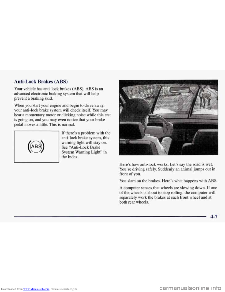
Your vehicle has anti-lock brakes (ABS). ABS is an
advanced electronic braking system that will help
prevent a braking slud.
When you start your engine and begin to drive away,
your anti-lock brake system will check itself. You may
hear a momentary motor or clicking noise while this test
is going on, and you may even notice that your brake
pedal moves a little.
This is normal.
If there’s a problem with the
anti-lock brake system, this
warning light will stay on.
See “Anti-Lock Brake
System Warning Light” in
the Index.
Here’s how anti-lock works. Let’s say the road
is wet.
You’re driving safely. Suddenly an animal jumps out in
front
of you.
You slam on the brakes. Here’s what happens with ABS.
A computer senses that wheels are slowing down. If one
of the wheels is about to stop rolling, the computer will
separately work the brakes at each front wheel and at
both rear wheels.
4-7
Page 205 of 378
Downloaded from www.Manualslib.com manuals search engine Skidding
In a skid, a driver can lose control of the vehicle.
Defensive drivers avoid most skids by taking reasonable care suited to existing conditions, and by not “overdriving”\
those conditions. But skids are always possible.
The three types of skids correspond to your vehicle’s
three control systems. In the braking skid, your wheels
aren’t rolling. In the steering or cornering skid, too
much speed or steering in a curve causes tires to slip and
lose cornering force. And in the acceleration skid, too
much throttle causes the driving wheels to spin.
A cornering skid is best handled by easing your foot
off
the accelerator pedal.
Remember: Any traction control system helps avoid
only the acceleration skid.
If your TCS system is off, then an acceleration slud
is also best handled by easing your foot
off the
accelerator pedal.
If your vehicle starts to slide, ease your foot
off the
accelerator pedal and quickly steer the way you want the
vehicle to
go. If you start steering quickly enough, your
vehicle may straighten out. Always be ready for a
second skid if it occurs. Of
course, traction is reduced when water, snow, ice,
gravel or other material is on the road. For safety, you’ll\
want to slow down and adjust your driving to these
conditions. It is important to slow down on slippery
surfaces because stopping distance will be longer and
vehicle control more limited.
While driving on a surface with reduced traction, try
your best to avoid sudden steering, acceleration or braking (including engine braking by shifting to a lower
gear). Any sudden changes could cause the tires to slide.
You may not realize the surface is slippery until your
vehicle
is skidding. Learn to recognize warning clues --
such as enough water, ice or packed snow on the road to
make a “mirrored surface”
-- and slow down when you
have any doubt.
Remember: Any anti-lock brake system
(ABS) helps
avoid only the braking skid.
4-14
Page 306 of 378
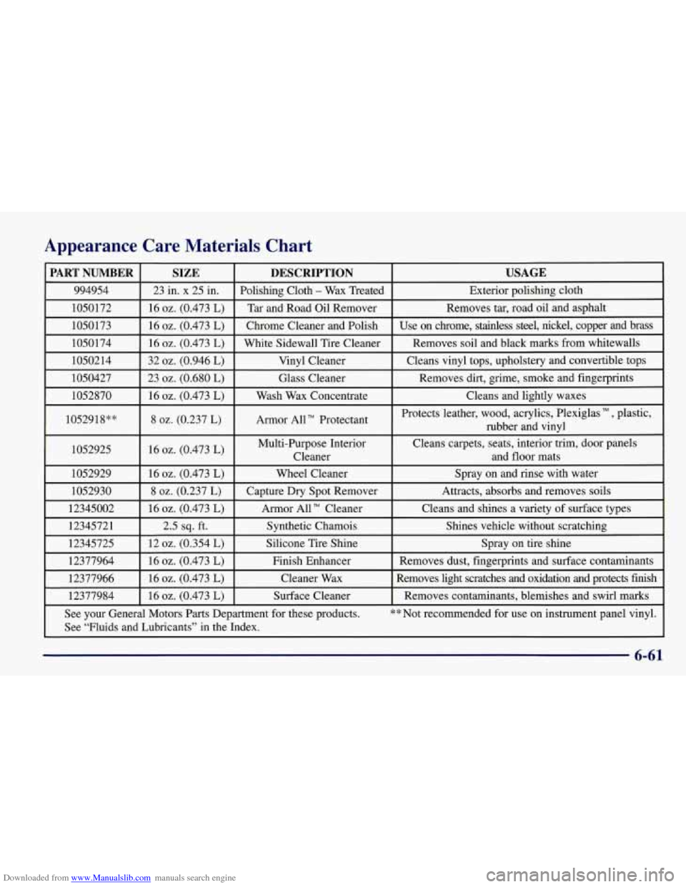
Downloaded from www.Manualslib.com manuals search engine Appearance Care Materials Chart
PART NUMBER USAGE DESCRIPTION
SIZE
994954
Exterior polishing cloth
Polishing Cloth - Wax
Treated
23 in. x 25 in.
1050172
Use on chrome, stainless steel, nickel, copper and brass
Chrome Cleaner and Polish 16
02. (0.473 L) 1050173 Removes
tar, road oil and asphalt
Tar and Road Oil Remover
16 02. (0.473 L)
1050174
I 16 oz. (0.473 L) I White Sidewall Tire Cleaner I Removes soil and black marks from whitewalls
1050214
I 32 oz. (0.946 L) I Vinyl Cleaner I Cleans vinyl tops, upholstery and convertible tops I
1050427 I 23 02. (0.680 L) I Glass Cleaner I Removes dirt, grime, smoke and fingerprints
1052870
I 16 02. (0.473 L) I Wash Wax Concentrate I Cleans and lightly waxes
1052918**
I 8 02. (0.237 L) I Armor AUT’ Protectant I
Protects leather, wood, acrylics, Plexiglas , plastic,
rubber and vinyl
1052925
I 16 02. (0.473 L) I Multi-Purpose Interior Cleans carpets,
seats, interior trim, door panels
I Cleaner and floor mats
1052929
I 16 oz. (0.473 L) I Wheel Cleaner I Spray on and rinse with water
1052930
Shines vehicle without scratching Synthetic Chamois
2.5 sq. ft.
12345721 Cleans and
shines a variety
of surface types Armor
All TM Cleaner
16 oz. (0.473 L)
12345002 Attracts, absorbs and
removes soils
Capture
Dry Spot Remover 8 02. (0.237 L)
12345725
See your General Motors Parts Department for these products.
** Not recommended for use on instrument panel vinyl.
Removes
contaminants, blemishes and swirl marks Surface Cleaner
16
oz. (0.473 L) 12377984 Removes light scratches and oxidation and protects finish Cleane\
r
Wax 16 02. (0.473 L)
12377966 Removes
dust, fingerprints and surface contaminants
Finish Enhancer
16
02. (0.473 L)
12377964 Spray
on tire shine Silicone
Tire Shine 12 02. (0.354 L)
See “Fluids and Lubricants” in the Index.
6-61
Page 312 of 378
Downloaded from www.Manualslib.com manuals search engine Engine Compartment Fuse Block
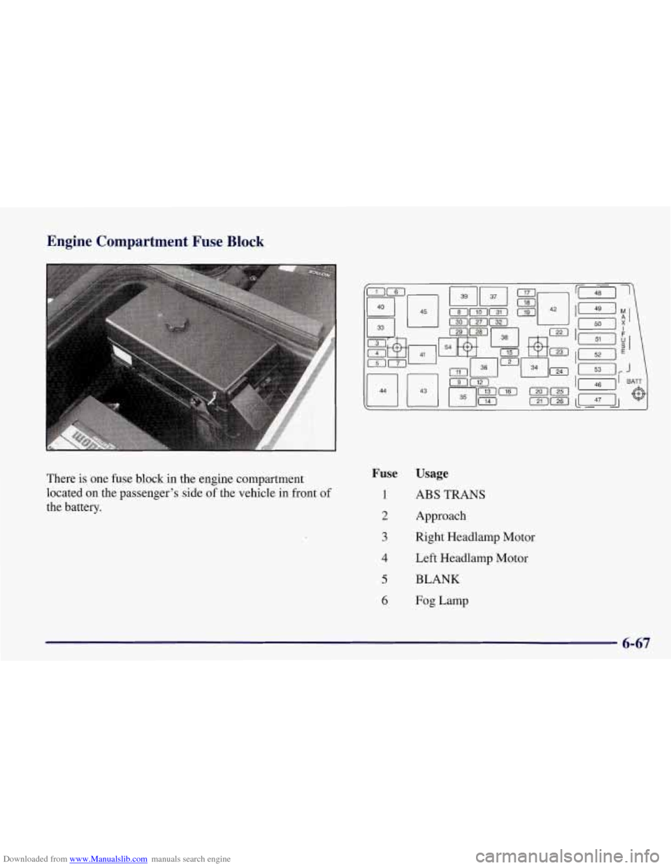
There is one fuse block in the engine compartment
located
on the passenger’s side of the vehicle in front of
the battery.
Fuse Usage
1 ABS TRANS
2 Approach
3 Right Headlamp Motor
4 Left Headlamp Motor
5 BLANK
6 Fog Lamp
6-67
Page 313 of 378
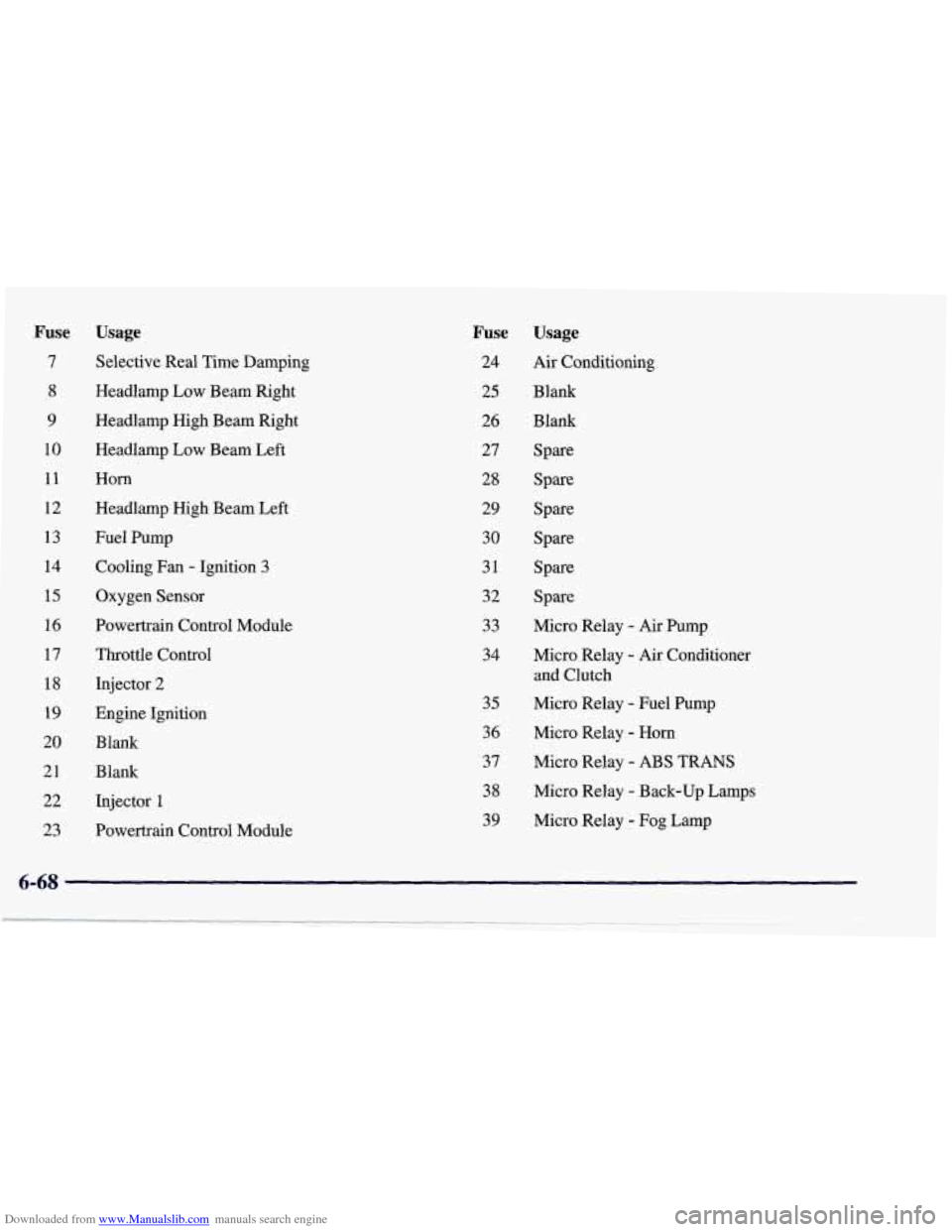
Downloaded from www.Manualslib.com manuals search engine Fuse
7
8
9
10
11
12 13
14
15
16
17
18 19
20 21
22
23
Usage
Selective Real Time Damping
Headlamp Low Beam Right
Headlamp High Beam Right
Headlamp Low Beam Left
Horn
Headlamp High Beam Left
Fuel Pump Cooling Fan
- Ignition 3
Oxygen Sensor
Powertrain Control Module
Throttle Control
Injector
2
Engine Ignition
Blank
Blank
Injector
1
Powertrain Control Module
Fuse
24
25
26
27
28
29
30
31
32 33
34
35
36
37
38
39
Usage
Air Conditioning
Blank B 1,ank
Spare
Spare
Spare Spare
Spare Spare
Micro Relay
- Air Pump
Micro Relay
- Air Conditioner
and Clutch
Micro Relay
- Fuel Pump
Micro Relay
- Horn
Micro Relay - ABS TRANS
Micro Relay - Back-up Lamps
Micro Relay
- Fog Lamp
6-68
Page 358 of 378
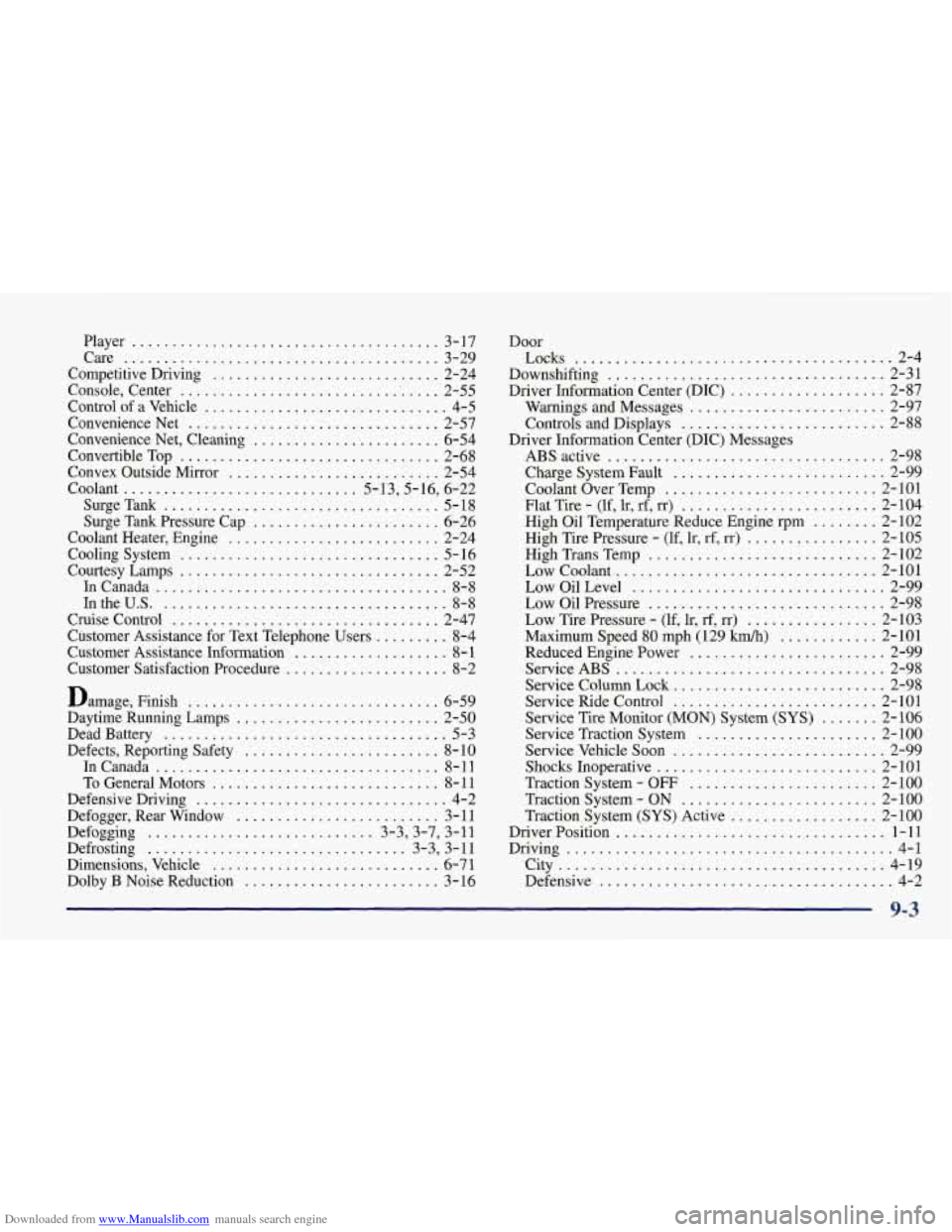
Downloaded from www.Manualslib.com manuals search engine Player ...................................... 3-17
Care
....................................... 3-29
Competitive Driving
............................ 2-24
Console. Center
........................... .. .... 2-55
Control of a Vehicle
.............................. 4-5
Convenience Net
............................... 2-57
Convenience Net. Cleaning
....................... 6-54
Convertible Top
................................ 2-68
Convex Outside Mirror
.......................... 2-54
Coolant
............................. 5.13.5.16. 6.22
SurgeTank
.................................. 5-18
Surge Tank Pressure Cap
....................... 6-26
Coolant Heater. Engine
.......................... 2-24
CoolingSystem
................................ 5-16
Courtesy Lamps
................................ 2-52
InCanada
.................................... 8-8
1ntheU.S. ................................... 8-8
Cruise Control ................................. 2-47
Customer Assistance for Text Telephone Users
......... 8-4
Customer Assistance Infomation
................... 8- 1
Customer Satisfaction Procedure .................... 8-2
Damage. Finish
............................... 6-59
Daytime Running Lamps
......................... 2-50
Dead Battery
................................... 5-3
Defects. Reporting Safety
........................ 8- 10
InCanada
................................... 8-11
To General Motors
............................ 8- 11
Defensive Driving
............................... 4-2
Defogger. Rear Window
......................... 3- 11
Defogging ............................ 3-3.3-7. 3-11
Defrosting ................................ 3-3. 3-11
Dimensions. Vehicle
............................ 6-7 1
Dolby B Noise Reduction ........................ 3-16 Door
Locks
....................................... 2-4
Downshifting
.................................. 2-31
Driver Information Center (DIC)
................... 2-87
Warnings and Messages
........................ 2-97
Controls and Displays
......................... 2-88
ABS active
.................................. 2-98
Charge System Fault
.......................... 2-99
Coolant Over Temp
.......................... 2- 101
Flat Tire
. (lf. lr. rf. rr) ........................ 2-104
High Oil Temperature Reduce Engine rpm
........ 2- 102
High Tire Pressure
. (If. lr. rf. rr) ................ 2-105
High Trans Temp
............................ 2- 102
Low Coolant
................................ 2- 101
LowOilLevel ............................... 2-99
Low
Oil Pressure ............................. 2-98
Low Tire Pressure
. (If. lr. rf. rr) ................ 2-103
Maximum Speed
80 mph (129 Wh) ............ 2-101
Reduced Engine Power
........................ 2-99
ServiceABS
................................. 2-98
Service Column Lock
.......................... 2-98
Service Ride Control
......................... 2- 101
Service Tire Monitor (MON) System (SYS) ....... 2-106
Service Traction System
...................... 2-100
Service Vehicle Soon
.......................... 2-99
Shocks Inoperative
........................... 2- 10 1
Traction System
- OFF ....................... 2-100
Traction System
- ON ........................ 2-100
Traction System
(SYS) Active .................. 2-100
Driver Position
................................. 1-11
Driving
........................................ 4-1
City
........................................ 4-19
Defensive
.................................... 4-2
Driver Information Center
(DIC) Messages
9-3