horn CHEVROLET DYNASTY 1993 Service Manual
[x] Cancel search | Manufacturer: CHEVROLET, Model Year: 1993, Model line: DYNASTY, Model: CHEVROLET DYNASTY 1993Pages: 2438, PDF Size: 74.98 MB
Page 22 of 2438
GROUP TAB LOCATOR
Introduction
8ABattery/Starting/Charging
Systems Diagnostics
8BBattery/Starter/Generator Service
8COverhead Console
8DIgnition Systems
8EInstrument Panel and Gauges
8FAudio System
8GHorns
8HVehicle Speed Control
8JTurn Signal/Hazard Warning Flasher
8KWindshield Wiper/Washer Systems
8LLamps
8MRestraint Systems
8NRear Window Defogger
8PPower Locks
8QVehicle Theft Security System
8RPower Seats
8SPower Windows
8TPower Mirrors
8UChime Warning/Reminder Systems
14Fuel Systems
25Emission Control Systems
Component and System Index
Service Manual Comment Forms (Rear of Manual)
Page 33 of 2438
COMPONENT AND SYSTEM INDEX
Name Group-page Name Group-page
AUDIO SYSTEM ............................ 8F-1
ANTENNAS ............................ 8F-20
COMPACT DISC PLAYER ................... 8F-30
RADIOS ............................... 8F-1
SPEAKERS ............................. 8F-24
BATTERY/STARTER/GENERATOR SERVICE ..........8B-1
BATTERY REMOVAL, INSTALLATION AND SERVICE . . 8B-1
GENERATOR ............................ 8B-9
SPECIFICATIONS ........................ 8B-12
STARTER .............................. 8B-4
BATTERY/STARTING/CHARGING SYSTEMS DIAGNOSTICS ........................... 8A-1
BATTERY TEST PROCEDURES ON-VEHICLE .......8A-3
FAULT CODESÐON BOARD DIAGNOSTICS .......8A-23
GENERAL INFORMATION .................... 8A-1
GENERATOR TEST PROCEDURES ON VEHICLE ....8A-19
IGNITION OFF DRAW (IOD) ..................8A-9
SPECIFICATIONS ........................ 8A-28
STARTER TEST PROCEDURES ON VEHICLE ......8A-11
CHIME WARNING/REMINDER SYSTEM ............8U-1
EMISSION CONTROL SYSTEMS .................25-1
EVAPORATIVE EMISSION CONTROLS ...........25-1
EXHAUST EMISSION CONTROLS ..............25-17
FUEL SYSTEMS ............................ 14-1
2.2L TURBO III MULTI-PORT FUEL INJECTIONÐ GENERAL DIAGNOSIS ................... 14-95
2.2L TURBO III MULTI-PORT FUEL INJECTIONÐ ON-BOARD DIAGNOSTICS ................14-100
2.2L TURBO III MULTI-PORT FUEL INJECTIONÐ SERVICE PROCEDURES .................14-107
2.2L TURBO III MULTI-PORT FUEL INJECTIONÐ SYSTEM OPERATION .................... 14-83
2.2L/2.5L SINGLE POINT FUEL INJECTIONÐ GENERAL DIAGNOSIS ................... 14-35
2.2L/2.5L SINGLE POINT FUEL INJECTIONÐ ON-BOARD DIAGNOSTICS .................14-41
2.2L/2.5L SINGLE POINT FUEL INJECTIONÐ SERVICE PROCEDURES .................. 14-48
2.2L/2.5L SINGLE POINT FUEL INJECTIONÐ SYSTEM OPERATION .................... 14-24
2.5L FLEXIBLE FUEL MULTI-PORT FUEL INJECTIONÐGENERAL DIAGNOSIS ..........14-66
2.5L FLEXIBLE FUEL MULTI-PORT FUEL INJECTIONÐON-BOARD DIAGNOSTICS ........14-70
2.5L FLEXIBLE FUEL MULTI-PORT FUEL INJECTIONÐSERVICE PROCEDURES .........14-77
2.5L FLEXIBLE FUEL MULTI-PORT FUEL INJECTIONÐSYSTEM OPERATION ...........14-55
3.0L MULTI-PORT FUEL INJECTIONÐGENERAL DIAGNOSIS .......................... 14-125
3.0L MULTI-PORT FUEL INJECTIONÐON-BOARD DIAGNOSTICS ........................ 14-130
3.0L MULTI-PORT FUEL INJECTIONÐSERVICE PROCEDURES ........................ 14-138
3.0L MULTI-PORT FUEL INJECTIONÐSYSTEM OPERATION ......................... 14-113
3.3L AND 3.8L MULTI-PORT FUEL INJECTIONÐ GENERAL DIAGNOSIS ................... 14-157 3.3L AND 3.8L MULTI-PORT FUEL INJECTIONÐ
ON-BOARD DIAGNOSTICS ................14-162
3.3L AND 3.8L MULTI-PORT FUEL INJECTIONÐ SERVICE PROCEDURES .................14-169
3.3L AND 3.8L MULTI-PORT FUEL INJECTIONÐ SYSTEM OPERATION ................... 14-145
ACCELERATOR PEDAL AND THROTTLE CABLE ....14-21
FUEL DELIVERY SYSTEM .................... 14-3
FUEL TANKS ........................... 14-14
GENERAL INFORMATION .................... 14-1
SPECIFICATIONS ........................ 14-178
HORNS ................................. 8G-1
IGNITION SYSTEMS ......................... 8D-1
2.2L TBI, 2.5L TBI, 2.5L MPI AND 3.0L IGNITION SYSTEMSÐDIAGNOSTIC PROCEDURES .......8D-11
2.2L TBI, 2.5L TBI, 2.5L MPI AND 3.0L IGNITION SYSTEMSÐSERVICE PROCEDURES ..........8D-14
2.2L TBI, 2.5L TBI, 2.5L MPI AND 3.0L IGNITION SYSTEMSÐSYSTEM OPERATION ............8D-1
2.2L TURBO III, 3.3L AND 3.8L IGNITION SYSTEMÐDIAGNOSTIC PROCEDURES ........8D-35
2.2L TURBO III, 3.3L AND 3.8L IGNITION SYSTEMÐSYSTEM OPERATION ............8D-24
2.2L TURBO III, 3.3L AND 3.8L IGNITION SYSTEMSÐSERVICE PROCEDURES ..........8D-39
IGNITION SWITCH ....................... 8D-45
SPECIFICATIONS ........................ 8D-47
INSTRUMENT PANEL AND GAUGES ...............8E-1
AA BODY .............................. 8E-1
AC AND AY BODIES ...................... 8E-23
AG AND AJ BODIES ...................... 8E-42
AP BODY ............................. 8E-58
LAMPS .................................. 8L-1
BULB APPLICATION TABLE ..................8L-38
CONCEALED HEADLAMPS ..................8L-27
EXTERIOR LAMP SWITCHES AND HEADLAMP ALIGNMENT ........................... 8L-3
EXTERIOR LAMP SYSTEMS .................8L-25
EXTERIOR LAMPSÐAA BODY ................8L-7
EXTERIOR LAMPSÐAC BODY ...............8L-10
EXTERIOR LAMPSÐAG BODY ...............8L-14
EXTERIOR LAMPSÐAJ BODY ................8L-16
EXTERIOR LAMPSÐAP BODY ...............8L-19
EXTERIOR LAMPSÐAY-BODY ................8L-22
GENERAL INFORMATION .................... 8L-1
ILLUMINATED ENTRY SYSTEM ...............8L-33
OVERHEAD CONSOLE ........................ 8C-1
AA BODY .............................. 8C-1
AC AND AY BODY ........................ 8C-6
AG AND AJ BODIES ...................... 8C-13
AP BODY ............................. 8C-21
POWER LOCKS ............................ 8P-1
POWER MIRRORS ..........................8T-1
POWER SEATS ............................ 8R-1
POWER WINDOWS .......................... 8S-1
REAR WINDOW DEFOGGER .................... 8N-1
RESTRAINT SYSTEMS ....................... 8M-1
TURN SIGNALS AND HAZARD WARNING FLASHER ....8J-1
VEHICLE SPEED CONTROL .................... 8H-1
Page 597 of 2438
HORNS
CONTENTS
page page
GENERAL INFORMATION .................. 1
HORN SWITCH REPLACEMENT ............ 3 TESTING HORN SYSTEM
................. 1
GENERAL INFORMATION
WARNING: ON VEHICLES EQUIPPED WITH AIR
BAG, SEE GROUP 8M, RESTRAINT SYSTEMS FOR
STEERING WHEEL OR COLUMN REMOVAL PROCE-
DURES.
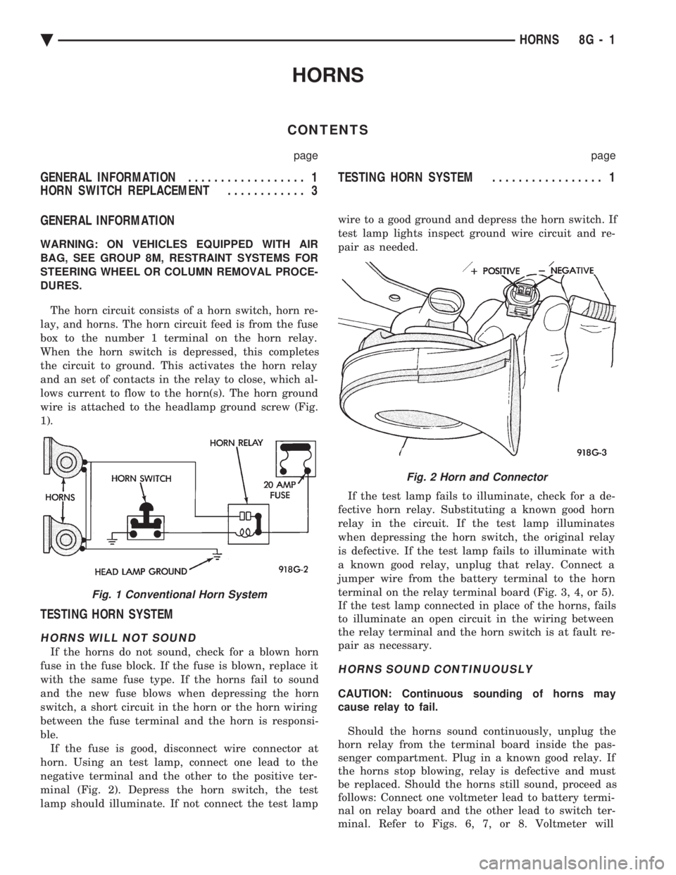
The horn circuit consists of a horn switch, horn re-
lay, and horns. The horn circuit feed is from the fuse
box to the number 1 terminal on the horn relay.
When the horn switch is depressed, this completes
the circuit to ground. This activates the horn relay
and an set of contacts in the relay to close, which al-
lows current to flow to the horn(s). The horn ground
wire is attached to the headlamp ground screw (Fig.
1).
TESTING HORN SYSTEM
HORNS WILL NOT SOUND
If the horns do not sound, check for a blown horn
fuse in the fuse block. If the fuse is blown, replace it
with the same fuse type. If the horns fail to sound
and the new fuse blows when depressing the horn
switch, a short circuit in the horn or the horn wiring
between the fuse terminal and the horn is responsi-
ble. If the fuse is good, disconnect wire connector at
horn. Using an test lamp, connect one lead to the
negative terminal and the other to the positive ter-
minal (Fig. 2). Depress the horn switch, the test
lamp should illuminate. If not connect the test lamp wire to a good ground and depress the horn switch. If
test lamp lights inspect ground wire circuit and re-
pair as needed.
If the test lamp fails to illuminate, check for a de-
fective horn relay. Substituting a known good horn
relay in the circuit. If the test lamp illuminates
when depressing the horn switch, the original relay
is defective. If the test lamp fails to illuminate with
a known good relay, unplug that relay. Connect a
jumper wire from the battery terminal to the horn
terminal on the relay terminal board (Fig. 3, 4, or 5).
If the test lamp connected in place of the horns, fails
to illuminate an open circuit in the wiring between
the relay terminal and the horn switch is at fault re-
pair as necessary.
HORNS SOUND CONTINUOUSLY
CAUTION: Continuous sounding of horns may
cause relay to fail.
Should the horns sound continuously, unplug the
horn relay from the terminal board inside the pas-
senger compartment. Plug in a known good relay. If
the horns stop blowing, relay is defective and must
be replaced. Should the horns still sound, proceed as
follows: Connect one voltmeter lead to battery termi-
nal on relay board and the other lead to switch ter-
minal. Refer to Figs. 6, 7, or 8. Voltmeter will
Fig. 1 Conventional Horn System
Fig. 2 Horn and Connector
Ä HORNS 8G - 1
Page 598 of 2438
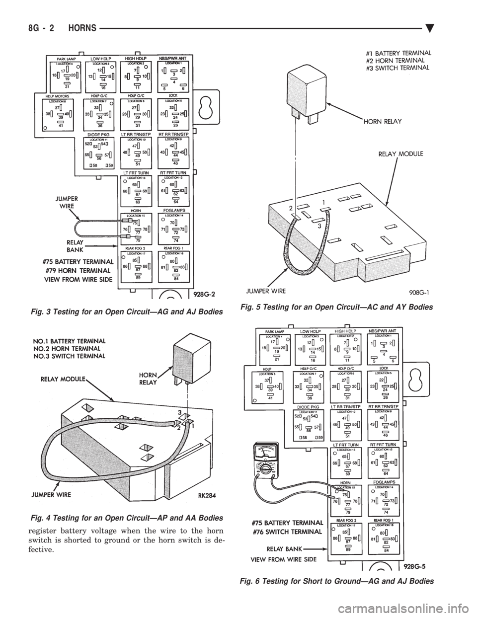
register battery voltage when the wire to the horn
switch is shorted to ground or the horn switch is de-
fective.
Fig. 3 Testing for an Open CircuitÐAG and AJ Bodies
Fig. 4 Testing for an Open CircuitÐAP and AA Bodies
Fig. 5 Testing for an Open CircuitÐAC and AY Bodies
Fig. 6 Testing for Short to GroundÐAG and AJ Bodies
8G - 2 HORNS Ä
Page 599 of 2438
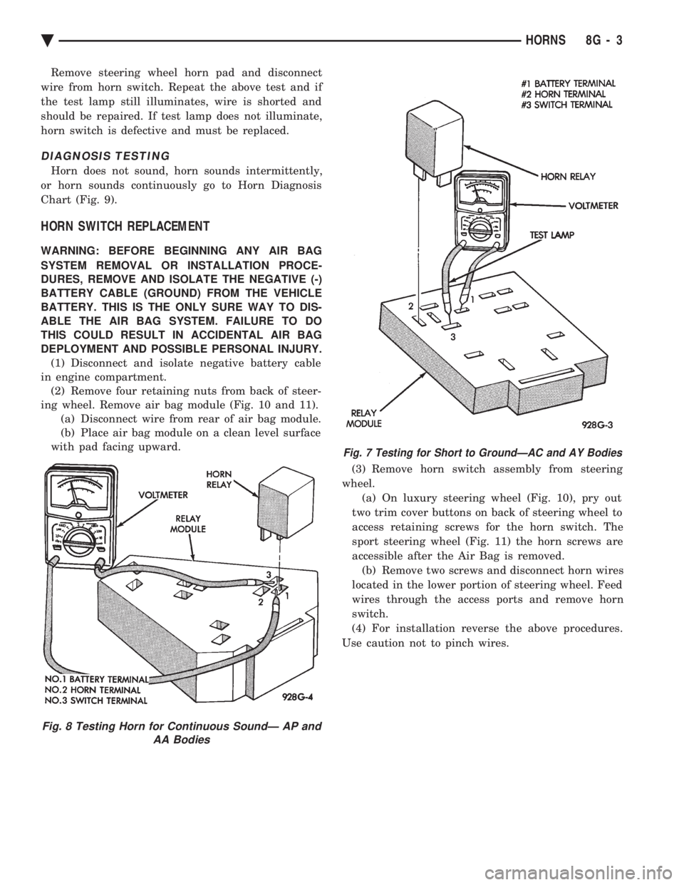
Remove steering wheel horn pad and disconnect
wire from horn switch. Repeat the above test and if
the test lamp still illuminates, wire is shorted and
should be repaired. If test lamp does not illuminate,
horn switch is defective and must be replaced.
DIAGNOSIS TESTING
Horn does not sound, horn sounds intermittently,
or horn sounds continuously go to Horn Diagnosis
Chart (Fig. 9).
HORN SWITCH REPLACEMENT
WARNING: BEFORE BEGINNING ANY AIR BAG
SYSTEM REMOVAL OR INSTALLATION PROCE-
DURES, REMOVE AND ISOLATE THE NEGATIVE (-)
BATTERY CABLE (GROUND) FROM THE VEHICLE
BATTERY. THIS IS THE ONLY SURE WAY TO DIS-
ABLE THE AIR BAG SYSTEM. FAILURE TO DO
THIS COULD RESULT IN ACCIDENTAL AIR BAG
DEPLOYMENT AND POSSIBLE PERSONAL INJURY. (1) Disconnect and isolate negative battery cable
in engine compartment. (2) Remove four retaining nuts from back of steer-
ing wheel. Remove air bag module (Fig. 10 and 11). (a) Disconnect wire from rear of air bag module.
(b) Place air bag module on a clean level surface
with pad facing upward.
(3) Remove horn switch assembly from steering
wheel. (a) On luxury steering wheel (Fig. 10), pry out
two trim cover buttons on back of steering wheel to
access retaining screws for the horn switch. The
sport steering wheel (Fig. 11) the horn screws are
accessible after the Air Bag is removed. (b) Remove two screws and disconnect horn wires
located in the lower portion of steering wheel. Feed
wires through the access ports and remove horn
switch.
(4) For installation reverse the above procedures.
Use caution not to pinch wires.
Fig. 8 Testing Horn for Continuous SoundÐ AP and AA Bodies
Fig. 7 Testing for Short to GroundÐAC and AY Bodies
Ä HORNS 8G - 3
Page 600 of 2438
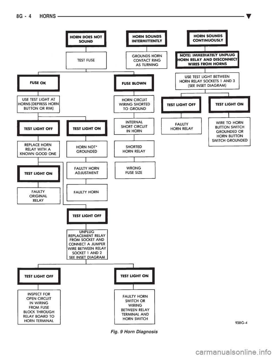
Fig. 9 Horn Diagnosis
8G - 4 HORNS Ä
Page 601 of 2438
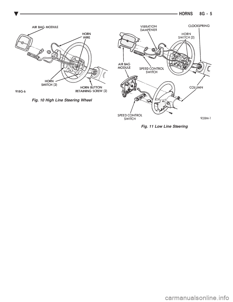
Fig. 10 High Line Steering Wheel
Fig. 11 Low Line Steering
Ä HORNS 8G - 5
Page 612 of 2438
(4) Disconnect electrical connector and vacuum
hose. (5) Pull cable away from servo to expose retaining
clip and remove clip attaching cable to servo.
INSTALLATION
(1) With throttle in full open position align hole in
vehicle speed control cable sleeve with hole in servo
pin and install retaining clip. (2) Connect vacuum hose to servo.
(3) Connect electrical connector.
(4) Position mounting bracket and install screws
attaching bracket and tighten to 12 N Im (105 in.
lbs.) torque. (5) Insert servo studs through holes in vehicle
speed control cable and mounting bracket. (6) Install nuts, tighten to 7 N Im (60 in. lbs.)
torque.
VEHICLE SPEED CONTROL SWITCH REMOVAL
The vehicle speed control switch is mounted in the
steering wheel and wired through the clock spring
device under the steering wheel hub (Fig.1).
WARNING: IF REMOVAL OF AIR BAG MODULE IS
NECESSARY, REFER TO GROUP 8M, RESTRAINT
SYSTEMS.
REMOVAL
(1) Turn off ignition.
(2) Remove two screws from back side of steering
wheel. (3) Rock switch away from air bag or horn pad
while lifting switch out of steering wheel. (4) Disconnect 4-way electrical connector.
INSTALLATION
(1) Turn off ignition.
(2) Connect 4-way electrical connector from clock
spring to switch. (3) Place switch in steering wheel, sliding the for-
ward edge of switch under air bag or horn pad. Line
up locating pins on switch with holes in steering
wheel frame. (4) Attach switch to wheel with two screws start-
ing with the screw at the left end of the switch.
8H - 10 VEHICLE SPEED CONTROL Ä
Page 613 of 2438
TURN SIGNALS AND HAZARD WARNING FLASHER
CONTENTS
page page
AG AND AJ BODIES ..................... 1
CHIME FUNCTIONÐAC, AG, AJ AND AY .... 1
DUAL-FUNCTION SWITCHÐAG AND AJ BODIES.5
GENERAL INFORMATION .................. 1
HAZARD WARNING SYSTEM .............. 1
MULTI-FUNCTION SWITCHÐAA, AC, AP AND AY BODIES .............................. 2 REMOTE TURN SIGNAL SWITCH REMOVALÐAG
AND AJ BODIES ....................... 5
TESTING PROCEDURES ................... 2
TURN SIGNAL AND HAZARD WARNING FLASHER LOCATION ............................ 6
TURN SIGNAL RELAYSÐAG AND AJ BODIES . 6
GENERAL INFORMATION
WARNING: ON VEHICLES EQUIPPED WITH AIR-
BAG, SEE GROUP 8M, RESTRAINT SYSTEMS FOR
AIRBAG REMOVAL PROCEDURES.
TURN SIGNALSÐAC, AY, AA AND AP BODIES
The turn signals are part of the multi-function switch.
Which contains electrical circuitry for turn signal, cor-
nering lamps, hazard warning, headlamp beam select,
headlamp optical horn, windshield wiper, pulse wipe
and windshield washer switching. The integrated switch
assembly is mounted to the left hand side of the steer-
ing column. When the driver wishes to signal his inten-
tions to change direction of travel, he moves the lever
upward to cause the right signals to flash and down-
ward to cause the left signals to flash. After completion
of a turn the system is deactivated automatically. As
the steering wheel returns to the straight ahead posi-
tion, a canceling cam of two lobes molded to the clock-
spring mechanism comes in contact with the cancel
actuator on the turn signal multi-function switch as-
sembly. Either cam lobe, pushing on the cancel actua-
tor, returns the switch to the off position. If only momentary signaling such as indication of a
lane change is desired, the switch is actuated to a left
or right intermediate detent position. In this position
the signal lamps flash as described above, but the
switch returns to the OFF position as soon as the lever
is released.
When the system is activated, 1 of 2 indicator
lamps mounted in the instrument cluster flashes in
unison with the turn signal lamps, indicating to the
driver that the system is operating.
AG AND AJ BODIES
The turn signals are actuated with lever on the left
side of the instrument panel switch pod. When the
driver wishes to signal his intentions to change di- rection of travel, he moves the lever upward to cause
the right signals to flash and downward to cause the
left signals to flash. After completion of a turn the system is deacti-
vated automatically. The cancellation switch in the
steering column sends a signal to a remote turn sig-
nal switch in the switch pod to cancel the turn signal
function. As the steering wheel returns to the
straight ahead position from a turn, a cancel cam
which is located on the steering wheel contacts a
cancel flipper located on the cancellation switch.
When the flipper is contacted by the cancel cam in
the proper rotational direction, the cancel switch
sends a signal to the remote turn signal switch. If only momentary signaling such as indication of a
lane change is desired, the switch is actuated to a
left or right intermediate detent position. In this po-
sition the signal lamps flash as described above, but
the switch returns to the OFF position as soon as the
lever is released. When the system is activated, 1 of 2 indicator
lamps mounted in the instrument cluster flashes in
unison with the turn signal lamps, indicating to the
driver that the system is operating.
HAZARD WARNING SYSTEM
The hazard warning system is actuated by a push
button located on the top of the steering column be-
tween the steering wheel and the instrument panel.
The hazard switch is identified with a double trian-
gle on top of the button. Push and release the button
to turn the hazard function ON or OFF. The button
will move out from the steering column in the ON
position and will remain in toward the column in the
OFF position.
CHIME FUNCTIONÐAC, AG, AJ AND AY
The chime will sound after the vehicle has traveled
a distance of 0.6 miles at a speed above 15 miles per
hour.
Ä TURN SIGNALS AND HAZARD WARNING FLASHER 8J - 1
Page 614 of 2438
TESTING PROCEDURES
MULTI-FUNCTION SWITCH TESTS AA, AC, AP, AND AY BODIES
The multi-function switch contains electrical cir-
cuitry for turn signal, cornering lamps (optional),
hazard warning, headlamp beam select, headlamp
optical horn, windshield wiper, pulse wipe, and wind-
shield washer switching. This integrated switch as-
sembly is mounted to the left hand side of the
steering column. Should any function of the switch
fail, the entire switch assembly must be replaced. Re-
fer to Fig. 1 for diagnosis. To test the switch, first disconnect the negative
battery cable, then remove the upper and lower col-
umn covers to gain access to the switch connector.
Remove switch connector. Using an ohmmeter, test
for continuity (no resistance) between the terminals
of the switch as shown in the following continuity
charts (Fig 2 or 3).
DUAL-FUNCTION SWITCH TESTSÐAG AND AJ BODIES
The dual-function switch contains electrical cir-
cuitry for hazard warning switching, and circuitry
and electronics for turn signal cancellation. The
switch assembly is mounted to the left hand side of
the steering column. To test the hazard warning portion of the switch,
first disconnect the negative battery cable, then re-
move the upper and lower steering column covers to
gain access to the switch connector. Remove switch
connector (Fig. 4). Using an ohmmeter, test for con-
tinuity between the terminals of the switch as shown
in the following continuity chart (Fig. 5). To test the cancellation portion of the switch:
(1) Reconnect battery and switch connector (Fig.
5). (2) Connect voltmeter positive lead (+) to pin 8
and negative lead (-) to ground. (3) Place ignition switch to the ON position. Volt-
meter should read battery voltage. If no voltage is
present, check feed wire to pin 8. If battery voltage is
present continue with switch test.
RIGHT CANCELLATION TEST (1) Connect one side of a jumper wire to pin 3 and
the other end of jumper wire to ground. (2) Connect the positive lead (+) of a voltmeter to
pin 5 and the negative lead (-) to ground.
CAUTION: Do not allow pin 5 to become grounded
during test, switch failure will result.
(3) With the ignition switch in the ON position,
push the cancellation pawl down and read the volt-
meter. (4) The voltmeter should show at least 9 volts. (5) If voltage is 0 to 8 volts the cancellation switch
is defective. If voltage is 9 volts or more the cancel-
lation switch is working correctly.
LEFT CANCELLATION TEST
(1) Connect one side of a jumper wire to pin 4 and
the other end of jumper wire to ground. (2) Connect the positive lead (+) of a voltmeter to
pin 5 and the negative lead (-) to ground.
CAUTION: Do not allow pin 5 to become grounded
during test, switch failure will result.
(3) With the ignition switch in the ON position,
push the cancellation pawl up and read the voltme-
ter. (4) The voltmeter should show at least 9 volts.
(5) If voltage is 0 to 8 volts the cancellation switch
is defective. If voltage is 9 volts or more the cancel-
lation switch is working correctly.
REMOTE TURN SIGNAL SWITCH TESTÐAA AND AJ BODIES
The remote turn signal switch is located on the left
side of the instrument panel switch pod. To test, re-
move switch pod assembly from instrument panel.
Using an ohmmeter, test for continuity between the
terminals of the switch as shown in the following
continuity chart (Fig. 6). The white 7 way connector
next to the 14 way connector must be connected
when performing continuity checks.
CANCELLATION SOLENOID TESTÐAG AND AJ BODIES
To test the turn signal cancellation solenoid:
(1) Remove switch pod from instrument panel.
(2) Connect one end of a jumper wire to the posi-
tive terminal of the battery, the other end to pin 6 of
the turn signal switch 14 way connector. (3) Place turn signal switch in the left turn mode.
(4) Take a second jumper wire and connect one end
to a good ground. Momentarily touch the other end of
the jumper wire to pin 11 or 14. The solenoid should
energize, and return the switch to its center OFF po-
sition. (5) Place turn signal switch in the right turn
mode. (6) Repeat step 4. The solenoid should energize,
and return the switch to its center OFF position. (7) If switch does not return to center in either di-
rection, the switch is defective.
MULTI-FUNCTION SWITCHÐAA, AC, AP AND AY
BODIES
REMOVAL
(1) Disconnect negative battery cable.
(2) Tilt column only remove tilt lever.
8J - 2 TURN SIGNALS AND HAZARD WARNING FLASHER Ä