horn CHEVROLET DYNASTY 1993 User Guide
[x] Cancel search | Manufacturer: CHEVROLET, Model Year: 1993, Model line: DYNASTY, Model: CHEVROLET DYNASTY 1993Pages: 2438, PDF Size: 74.98 MB
Page 688 of 2438
CLOCKSPRING
WARNING: BEFORE BEGINNING ANY AIR BAG
SYSTEM REMOVAL OR INSTALLATION PROCE-
DURES, REMOVE AND ISOLATE THE BATTERY
NEGATIVE (-) CABLE (GROUND) FROM THE VEHI-
CLE BATTERY. THIS IS THE ONLY SURE WAY TO
DISABLE THE AIR BAG SYSTEM. FAILURE TO DO
SO COULD RESULT IN ACCIDENTAL AIR BAG DE-
PLOYMENT, AND POSSIBLE INJURY.
WHEN AN UNDEPLOYED AIR BAG ASSEMBLY
IS TO BE REMOVED FROM THE STEERING
WHEEL, DISCONNECT BATTERY GROUND CA-
BLE AND ISOLATE. ALLOW SYSTEM CAPACI-
TOR TO DISCHARGE FOR TWO MINUTES, THEN
BEGIN AIR BAG REMOVAL.
REMOVAL
(1) Place the front wheels in the straight ahead po-
sition before starting the repair. (2) Disconnect battery negative cable and isolate.
(3) Wait two minutes for the reserve capacitor to
discharge before removing undeployed module. (4) Remove the air bag module.
(5) Remove Speed Control switch and connector if
so equipped or cover. (6) Disconnect horn terminals.
(7) Remove the steering wheel.
(8) Remove upper and lower steering column
shrouds to gain access to clockspring wiring. (9) Disconnect the 2-way connector between the
clockspring and the instrument panel wiring harness
on top of the fuse block. (10) To remove, pull clockspring assembly from the
steering column by lifting locating fingers as neces-
sary. The clockspring cannot be repaired, and must
be replaced if faulty.
INSTALLATION
(1) Snap clockspring onto the steering column. If
the clockspring is not properly positioned, follow the
clockspring centering procedure before installing
steering wheel. (2) Connect the clockspring to the instrument
panel harness, ensure wiring locator clips are prop-
erly seated on wiring trough. Ensure harness locking
tabs are properly engaged. (3) Install steering column shrouds. Be sure air
bag wire is inside of shrouds. (4) Front wheels should still be in the straight-
ahead position. Install steering wheel, ensure the
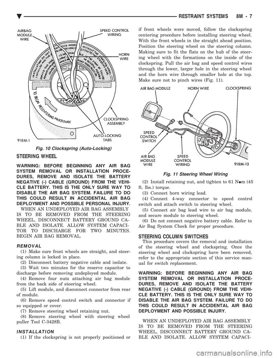
flats on hub align with clockspring. Pull the horn
lead through the smaller upper hole. Pull the air bag
and speed control leads through the larger bottom
hole. Ensure leads are not pinched under the steer-
ing wheel. (5) Connect the horn lead wire, then the air bag
lead wire to the air bag module. (6) Install the air bag module and tighten nuts to
9to11N Im (80 to 100 in. lb.) torque.
(7) Install speed control switch and connector or
cover. (8) Do not connect battery negative cable. Refer to
Air Bag Systems Check for proper procedure.
CLOCKSPRING CENTERING PROCEDURE
If the rotating tape within the clockspring is not
positioned properly with the steering wheel and the
front wheels, the clockspring may fail during use.
The following procedure MUST BE USED to center
the clockspring if it is not known to be properly po-
sitioned, or if the front wheels were moved from the
straight ahead position.
WARNING: BEFORE BEGINNING ANY AIR BAG
SYSTEM REMOVAL OR INSTALLATION PROCE-
DURES, REMOVE AND ISOLATE THE BATTERY
NEGATIVE (-) CABLE (GROUND) FROM THE VEHI-
CLE BATTERY. THIS IS THE ONLY SURE WAY TO
DISABLE THE AIR BAG SYSTEM. FAILURE TO DO
THIS COULD RESULT IN ACCIDENTAL AIR BAG
DEPLOYMENT AND POSSIBLE INJURY.
WHEN AN UNDEPLOYED AIR BAG ASSEMBLY
IS TO BE REMOVED FROM THE STEERING
WHEEL, DISCONNECT BATTERY GROUND CA-
BLE AND ISOLATE. ALLOW SYSTEM CAPACI-
TOR TO DISCHARGE FOR TWO MINUTES, THEN
BEGIN AIR BAG REMOVAL. (1) Place front wheels in the straight ahead posi-
tion. (2) Wait two minutes for the reserve capacitor to
discharge before removing undeployed module. (3) Refer to Steering Wheel procedures for removal
of air bag module and steering wheel. (4) Depress the two plastic locking pins to disen-
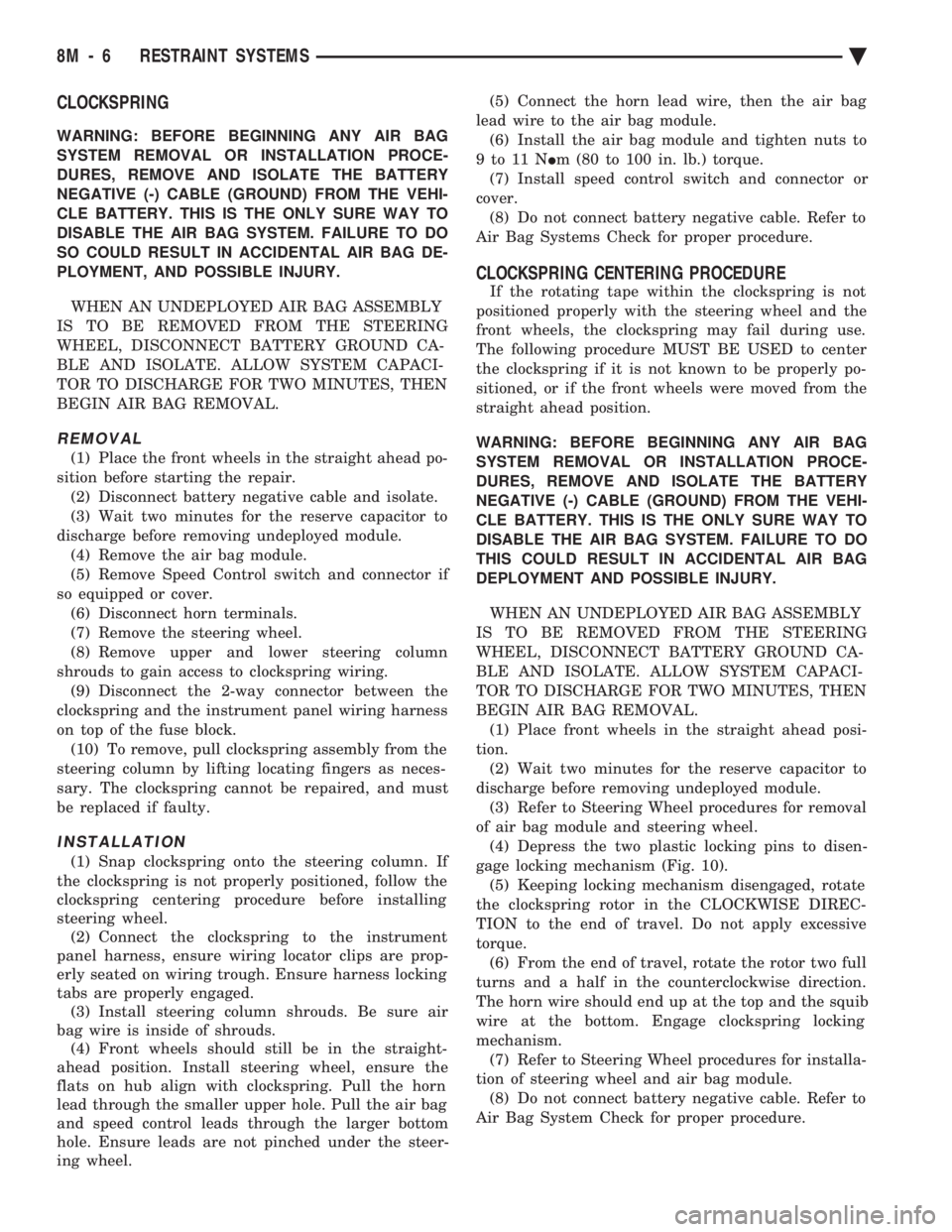
gage locking mechanism (Fig. 10). (5) Keeping locking mechanism disengaged, rotate
the clockspring rotor in the CLOCKWISE DIREC-
TION to the end of travel. Do not apply excessive
torque. (6) From the end of travel, rotate the rotor two full
turns and a half in the counterclockwise direction.
The horn wire should end up at the top and the squib
wire at the bottom. Engage clockspring locking
mechanism. (7) Refer to Steering Wheel procedures for installa-
tion of steering wheel and air bag module. (8) Do not connect battery negative cable. Refer to
Air Bag System Check for proper procedure.
8M - 6 RESTRAINT SYSTEMS Ä
Page 689 of 2438
STEERING WHEEL
WARNING: BEFORE BEGINNING ANY AIR BAG
SYSTEM REMOVAL OR INSTALLATION PROCE-
DURES, REMOVE AND ISOLATE THE BATTERY
NEGATIVE (-) CABLE (GROUND) FROM THE VEHI-
CLE BATTERY. THIS IS THE ONLY SURE WAY TO
DISABLE THE AIR BAG SYSTEM. FAILURE TO DO
THIS COULD RESULT IN ACCIDENTAL AIR BAG
DEPLOYMENT AND POSSIBLE PERSONAL INJURY. WHEN AN UNDEPLOYED AIR BAG ASSEMBLY
IS TO BE REMOVED FROM THE STEERING
WHEEL, DISCONNECT BATTERY GROUND CA-
BLE AND ISOLATE. ALLOW SYSTEM CAPACI-
TOR TO DISCHARGE FOR TWO MINUTES.
BEGIN AIR BAG REMOVAL.
REMOVAL
(1) Make sure front wheels are straight, and steer-
ing column is locked in place. (2) Disconnect battery negative cable and isolate.
(3) Wait two minutes for the reserve capacitor to
discharge before removing undeployed module. (4) Remove four nuts attaching air bag module
from the back side of steering wheel. (5) Lift module, and disconnect connector from rear
of module. (6) Remove speed control switch and connector if
so equipped or cover. (7) Remove steering wheel retaining nut.
(8) Remove steering wheel with steering wheel
puller Tool C-3428B.
INSTALLATION
(1) If the clockspring is not properly positioned or if front wheels were moved, follow the clockspring
centering procedure before installing steering wheel.
With the front wheels in the straight ahead position.
Position the steering wheel on the steering column.
Making sure to fit the flats on the hub of the steer-
ing wheel with the formations on the inside of the
clockspring. Pull the air bag and speed control wires
through the lower, larger hole in the steering wheel
and the horn wire through smaller hole at the top.
Make sure not to pinch wires (Fig. 11).
(2) Install retaining nut, and tighten to 61 N Im (45
ft. lbs.) torque. (3) Connect horn wiring lead.
(4) Connect 4-way connector to speed control
switch and attach switch to steering wheel. (5) Connect air bag lead wire to air bag module,
and secure module to steering wheel. (6) Do not connect negative battery cable. Refer to
Air Bag System Check for proper procedure.
STEERING COLUMN SWITCHES
This procedure covers the removal and installation
of the steering wheel and clockspring. Once the
steering wheel and clockspring have been removed,
refer to the appropriate section of this service man-
ual for switch replacement.
WARNING: BEFORE BEGINNING ANY AIR BAG
SYSTEM REMOVAL OR INSTALLATION PROCE-
DURES, REMOVE AND ISOLATE THE BATTERY
NEGATIVE (-) CABLE (GROUND) FROM THE VEHI-
CLE BATTERY. THIS IS THE ONLY SURE WAY TO
DISABLE THE AIR BAG SYSTEM. FAILURE TO DO
THIS COULD RESULT IN ACCIDENTAL AIR BAG
DEPLOYMENT AND POSSIBLE INJURY.
WHEN AN UNDEPLOYED AIR BAG ASSEMBLY
IS TO BE REMOVED FROM THE STEERING
WHEEL, DISCONNECT BATTERY GROUND CA-
BLE AND ISOLATE. ALLOW SYSTEM CAPACI-
Fig. 10 Clockspring (Auto-Locking)
Fig. 11 Steering Wheel Wiring
Ä RESTRAINT SYSTEMS 8M - 7
Page 699 of 2438
to the deck lid open position. If the pull down limit
switch is depressed at this time, the motor should
stop.(c) If these results are not obtained, replace the
pull down motor assembly.
REMOTE KEYLESS ENTRY
OPERATION
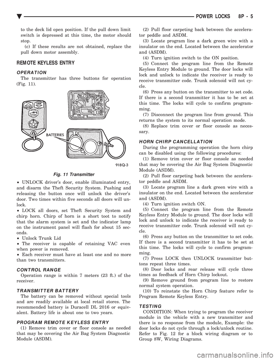
The transmitter has three buttons for operation
(Fig. 11).
² UNLOCK driver's door, enable illuminated entry,
and disarm the Theft Security System. Pushing and
releasing the button once will unlock the driver's
door. Two times within five seconds all doors will un-
lock.
² LOCK all doors, set Theft Security System and
chirp horn. Chirp of horn is a short toot to notify
that the alarm system is set and the indicator lamp
on the instrument panel will flash for about 15 sec-
onds.
² Unlock Trunk Lid
² The receiver is capable of retaining VAC even
when power is removed.
² Each receiver must have at least one and no more
than two transmitters.
CONTROL RANGE
Operation range is within 7 meters (23 ft.) of the
receiver.
TRANSMITTER BATTERY
The battery can be removed without special tools
and are readily available at local retail stores. The
recommended battery is Duracell DL 2016 or equiv-
alent. Battery life is about one to two years.
PROGRAM REMOTE KEYLESS ENTRY
(1) Remove trim cover or floor console as needed
that may be covering the Air Bag System Diagnostic
Module (ASDM). (2) Pull floor carpeting back between the accelera-
tor peddle and ASDM. (3) Locate program line a dark green wire with a
insulator on the end. Located between the accelerator
and (ASDM). (4) Turn ignition switch to the ON position.
(5) Connect the program line from the Remote
Keyless Entry Module to ground. The door locks will
lock and unlock to indicate the receiver is ready to
receive transmitter code. Trunk solenoid will not cy-
cle. (6) Press any button on the transmitter to set code.
If there is a second transmitter it has to be set at
this time. The locks will cycle to confirm program-
ming. (7) Disconnect the program line from ground. This
returns the system to its normal operation mode. (8) Replace trim cover or floor console as neces-
sary.
HORN CHIRP CANCELLATION
During the programming operation the horn chirp
can be disabled using the following procedures: (1) Remove trim cover or floor console as needed
that may be covering the Air Bag System Diagnostic
Module (ASDM). (2) Pull floor carpeting back between the accelera-
tor peddle and ASDM. (3) Locate program line a dark green wire with a
insulator on the end. Located between the accelerator
and (ASDM). (4) Turn ignition switch ON.
(5) Connect the program line from the Remote
Keyless Entry Module to ground. The door locks will
lock and unlock to indicate the receiver is ready to
receive transmitter code. Trunk solenoid will not cy-
cle. (6) Press any button on the transmitter to set code.
If there is a second transmitter it has to be set at
this time. The locks will cycle to confirm program-
ming. (7) Press LOCK then UNLOCK transmitter but-
tons repeat three times. (8) Door locks and rear release will cycle three
times as feedback of Horn Chirp lockout. (9) Remove ground from program line to restore
normal system operation. (10) To reinstate the Horn Chirp feature refer to
Program Remote Keyless Entry.
TESTING
CONDITION: When trying to program the receiver
module in the vehicle with a new transmitter and
there is no response from the module, Example: the
door locks do not cycle through a lock/unlock routine.
Refer to Fig. 12 for a block wiring diagram or to
Group 8W, Wiring Diagrams.
Fig. 11 Transmitter
Ä POWER LOCKS 8P - 5
Page 700 of 2438
(1) Be sure that the module has a battery feed
from the 20 Amp breaker in cavity 1 of the black
connector. Also affected would be the optical horn
and the stop lamps. (2) Be sure that the module has an ignition feed
from 5 Amp fuse in cavity 8 of the black connector.
Also affected would be the body computer, instru-
ment cluster and message center. (3) Be sure that the module has a ground from the
right side cowl behind the body computer to the cav-
ity 5 of the black connector. (4) Be sure that you are supplying a good ground
to the programming wire. (5) If the above circuits are good, replace the Re-
ceiver Module. CONDITION: Doors can be locked or unlocked with
the Keyless Entry transmitter. But the doors will not
lock. The Vehicle Theft Alarm system will not arm,
when using only the power door LOCK switch in the
driver's door. (1) Be sure you have not left key in the ignition
column lock cylinder. (2) If step 1 is OK, check the Key in Lock switch
circuit in the steering column for a short to ground. (3) In this problem the body computer controls the
LOCK function. Be sure that it is providing a battery
voltage output to the door lock relay. The door lock
relay controls the door lock motors. CONDITION: Doors will lock but Vehicle Theft
System will not arm when using the transmitter. (1) The Keyless Entry Receiver Module controls
the door lock signal to the door lock relay. The door
lock relay controls the door lock motors. Check for
battery voltage at cavity 10 of the Theft Alarm mod-
ule from the Receiver module. (2) If voltage is OK, replace Receiver module.
CONDITION: All doors except driver's door will
lock with the transmitter. (1) Test the driver's door output of the Receiver
Module for a ground. (2) If there is no ground at the pin, replace the Re-
ceiver module. (3) If there is a ground at the output, replace the
door lock motor. CONDITION: Only driver's door will lock with the
transmitter.
² Repair ground circuit to unlock relay
² Replace unlock relay
CONDITION: Doors do not lock with the transmit-
ter, but still get horn CHIRP that indicates that they
did lock. Replace Receiver module. CONDITION: Doors will lock with the transmitter
but there is no horn CHIRP. (1) Press horn button, listen horn sound.
(2) If the horn sounded, change horn relay. (3) Still no CHIRP, check continuity between the
horn relay and the receiver output pin. Repair as
necessary. (4) Still no horn CHIRP, replace the receiver mod-
ule. (5) If using a DRB II, refer to Body Diagnostic Pro-
cedures.
REMOTE KEYLESS MODULE REPLACEMENT
(1) Remove lower right instrument panel silencer.
(2) Remove glove box assembly.
(3) Remove three screws attaching the mounting
bracket to instrument panel. (4) Lower bracket and module assembly, to discon-
nect wire connector. (5) Remove two screws attaching the Remote Key-
less entry Module to bracket. (6) Remove two screws attaching the security mod-
ule to bracket. (7) To installation reverse above procedures.
LAMP OUTAGE MODULE REPLACEMENT
(1) Remove lower right instrument panel silencer.
(2) Remove glove box and ash receiver module.
(3) Remove three screws attaching the mounting
bracket to instrument panel. (4) Lower bracket and module assembly, to discon-
nect wire connectors. (5) Remove two screws attaching the Lamp Outage
Module to bracket. (6) Remove two screws attaching the security mod-
ule to bracket. (7) To installation reverse above procedures.
DOOR LOCK INHIBIT
The power door lock inhibit system prevents the
doors from being locked using the power door locks
when either of two conditions occur: (1) The key is in the ignition switch and any of the
doors are open. The ignition switch does not have to
be ON. (2) The key is in the ignition switch and the head-
lamp are on.
AC, AG, AJ AND AY BODIES
With the ignition switch in the ON or OFF position
and the driver's door open the Body Controller will
ignore the command to lock the power door locks.
Once the key is removed, or the driver's door is
closed, the Body Controller will allow the power door
locks to lock. Refer to Body Diagnostic Procedure
Manual for further testing procedures.
8P - 6 POWER LOCKS Ä
Page 703 of 2438
VEHICLE THEFT SECURITY SYSTEM
CONTENTS
page page
GENERAL INFORMATION .................. 1
SECURITY SYSTEM DOOR SWITCH REPLACEMENT ........................ 2
SECURITY SYSTEM HOOD SWITCH REPLACEMENT ........................ 2 SYSTEM SELF-TESTS
.................... 1
VEHICLE THEFT SECURITY SYSTEM MODULE REPLACEMENT ........................ 2
WHAT WILL TRIGGER THE SYSTEM ........ 1
GENERAL INFORMATION
JUMP-STARTING, VEHICLE EQUIPPED
WITH THEFT SECURITY SYSTEM . After the
booster battery has been connected, the Theft System
must be turned OFF. Using the key, lock then un-
lock either front door. This turns the Theft System
OFF and the remainder of the Jump-Starting proce-
dure can be followed. If this procedure is not followed, the Theft System
electronics will prevent the engine from starting. If a new Powertrain Control Module is installed,
the engine has to be cranked 20 times before the
alarm system activated. This passive system is designed to protect against
whole vehicle theft. The system monitors vehicle
doors, hood, trunk key cylinder, and ignition action
for unauthorized operation. The alarm activates by
sounding the horn, flashing the park and tail lamps,
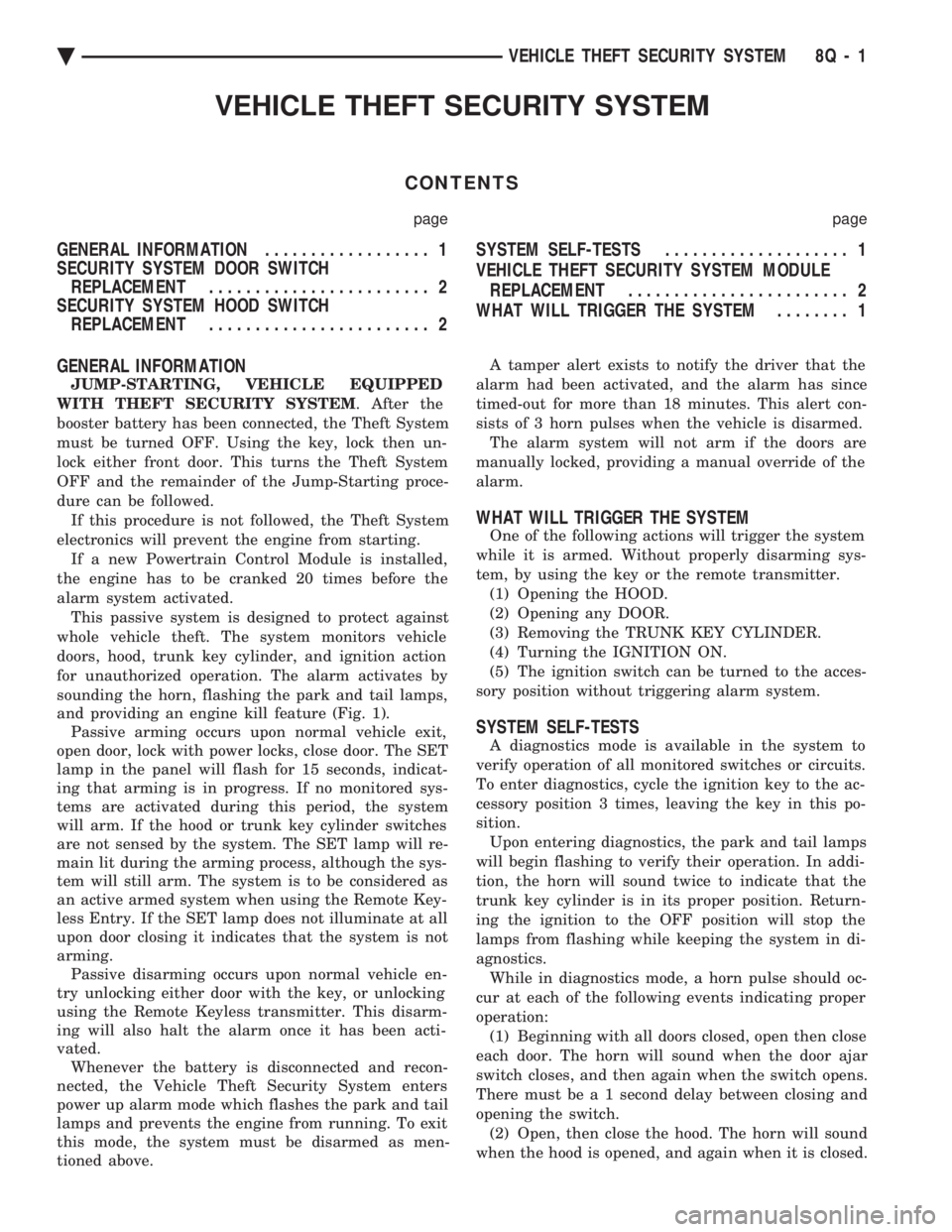
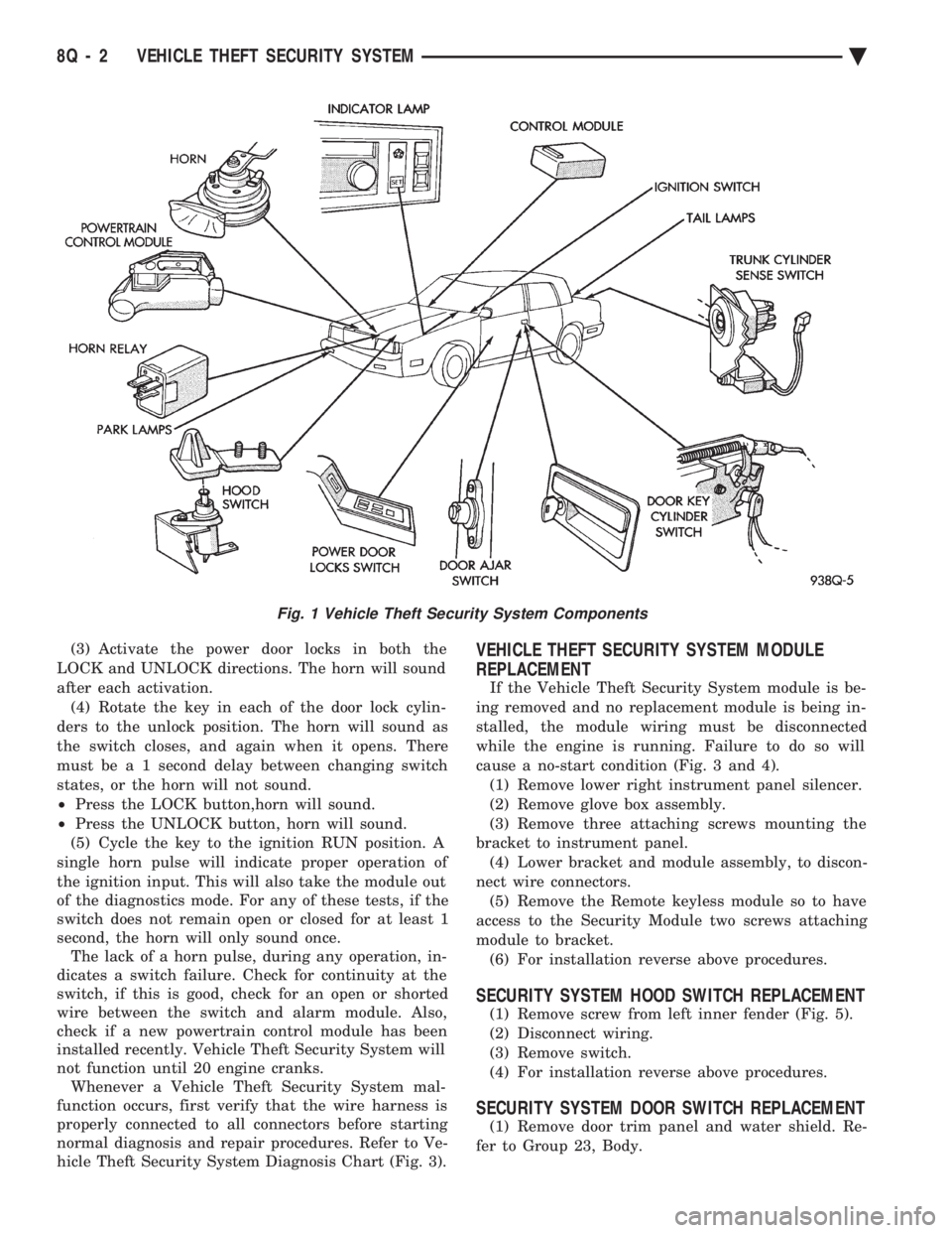
and providing an engine kill feature (Fig. 1). Passive arming occurs upon normal vehicle exit,
open door, lock with power locks, close door. The SET
lamp in the panel will flash for 15 seconds, indicat-
ing that arming is in progress. If no monitored sys-
tems are activated during this period, the system
will arm. If the hood or trunk key cylinder switches
are not sensed by the system. The SET lamp will re-
main lit during the arming process, although the sys-
tem will still arm. The system is to be considered as
an active armed system when using the Remote Key-
less Entry. If the SET lamp does not illuminate at all
upon door closing it indicates that the system is not
arming. Passive disarming occurs upon normal vehicle en-
try unlocking either door with the key, or unlocking
using the Remote Keyless transmitter. This disarm-
ing will also halt the alarm once it has been acti-
vated. Whenever the battery is disconnected and recon-
nected, the Vehicle Theft Security System enters
power up alarm mode which flashes the park and tail
lamps and prevents the engine from running. To exit
this mode, the system must be disarmed as men-
tioned above. A tamper alert exists to notify the driver that the
alarm had been activated, and the alarm has since
timed-out for more than 18 minutes. This alert con-
sists of 3 horn pulses when the vehicle is disarmed. The alarm system will not arm if the doors are
manually locked, providing a manual override of the
alarm.
WHAT WILL TRIGGER THE SYSTEM
One of the following actions will trigger the system
while it is armed. Without properly disarming sys-
tem, by using the key or the remote transmitter. (1) Opening the HOOD.
(2) Opening any DOOR.
(3) Removing the TRUNK KEY CYLINDER.
(4) Turning the IGNITION ON.
(5) The ignition switch can be turned to the acces-
sory position without triggering alarm system.
SYSTEM SELF-TESTS
A diagnostics mode is available in the system to
verify operation of all monitored switches or circuits.
To enter diagnostics, cycle the ignition key to the ac-
cessory position 3 times, leaving the key in this po-
sition. Upon entering diagnostics, the park and tail lamps
will begin flashing to verify their operation. In addi-
tion, the horn will sound twice to indicate that the
trunk key cylinder is in its proper position. Return-
ing the ignition to the OFF position will stop the
lamps from flashing while keeping the system in di-
agnostics. While in diagnostics mode, a horn pulse should oc-
cur at each of the following events indicating proper
operation: (1) Beginning with all doors closed, open then close
each door. The horn will sound when the door ajar
switch closes, and then again when the switch opens.
There must b e a 1 second delay between closing and
opening the switch. (2) Open, then close the hood. The horn will sound
when the hood is opened, and again when it is closed.
Ä VEHICLE THEFT SECURITY SYSTEM 8Q - 1
Page 704 of 2438
(3) Activate the power door locks in both the
LOCK and UNLOCK directions. The horn will sound
after each activation. (4) Rotate the key in each of the door lock cylin-
ders to the unlock position. The horn will sound as
the switch closes, and again when it opens. There
must b e a 1 second delay between changing switch
states, or the horn will not sound.
² Press the LOCK button,horn will sound.
² Press the UNLOCK button, horn will sound.
(5) Cycle the key to the ignition RUN position. A
single horn pulse will indicate proper operation of
the ignition input. This will also take the module out
of the diagnostics mode. For any of these tests, if the
switch does not remain open or closed for at least 1
second, the horn will only sound once. The lack of a horn pulse, during any operation, in-
dicates a switch failure. Check for continuity at the
switch, if this is good, check for an open or shorted
wire between the switch and alarm module. Also,
check if a new powertrain control module has been
installed recently. Vehicle Theft Security System will
not function until 20 engine cranks. Whenever a Vehicle Theft Security System mal-
function occurs, first verify that the wire harness is
properly connected to all connectors before starting
normal diagnosis and repair procedures. Refer to Ve-
hicle Theft Security System Diagnosis Chart (Fig. 3).VEHICLE THEFT SECURITY SYSTEM MODULE
REPLACEMENT
If the Vehicle Theft Security System module is be-
ing removed and no replacement module is being in-
stalled, the module wiring must be disconnected
while the engine is running. Failure to do so will
cause a no-start condition (Fig. 3 and 4). (1) Remove lower right instrument panel silencer.
(2) Remove glove box assembly.
(3) Remove three attaching screws mounting the
bracket to instrument panel. (4) Lower bracket and module assembly, to discon-
nect wire connectors. (5) Remove the Remote keyless module so to have
access to the Security Module two screws attaching
module to bracket. (6) For installation reverse above procedures.
SECURITY SYSTEM HOOD SWITCH REPLACEMENT
(1) Remove screw from left inner fender (Fig. 5).
(2) Disconnect wiring.
(3) Remove switch.
(4) For installation reverse above procedures.
SECURITY SYSTEM DOOR SWITCH REPLACEMENT
(1) Remove door trim panel and water shield. Re-
fer to Group 23, Body.
Fig. 1 Vehicle Theft Security System Components
8Q - 2 VEHICLE THEFT SECURITY SYSTEM Ä
Page 932 of 2438
Wiring Diagram
Name Sheet Number
Fan Control Relay ...........................33
Radiator Fan Motor ..........................33
Fog Lamps ............................. .55, 56
Fog Lamp Relay .............................48
Fog Lamp Switch .............................48
Front End Lighting ........................ .55, 56
Front Left Side Marker Lamp ....................56
Front Right Side Marker Lamp ...................55
Left Aero Hi-Low Beam Headlamp .................56
Left Fog Lamp .............................56
Left Park & Turn Signal Lamp ...................56
Right Aero Hi-Low Beam Headlamp ................55
Right Fog Lamp ............................55
Right Park & Turn Signal Lamp ..................55
Fuel Injection Ignition System (2.5L) .......12, 13, 14, 15, 16
Automatic Shutdown Relay ......................14
Distributor ................................15
Engine Coolant Sensor ........................15
EVAP/Purge Solenoid .........................13
Exhaust Gas Recirculation Diagnostic Solenoid .........13
Heated Oxygen Sensor ........................12
Idle Air Control Motor .........................12
Ignition Coil ...............................14
Injector ..................................16
MAP Sensor ...............................13
Powertrain Control Module ............12, 13, 14, 15, 16
Throttle Position (Sensor) ......................12
Vehicle Speed Senosr .........................15
Fuel Injection Ignition System Flex Fuel (2.5L Engine) ................ .17, 18, 19, 20, 21, 22
Auto Shutdown Relay ........................20
Distributor ...............................22
Engine Coolant Sensor ........................21
EVAP/Purge Solenoid .........................19
Fuel Sensor ...............................17
Heated Oxygen Sensor ........................18
Idle Air Control Motor ........................18
Ignition Coil ...............................20
Injectors .................................17
MAP Sensor ..............................19
Powertrain Control Module (PCM) . . . .17, 18, 19, 20, 21, 22
Throttle Position (Sensor) ......................18
Vehicle Speed Sensor ........................21
Fuel Injection Ignition System (3.0L) ............. .23, 24, 25, 26, 27, 28, 29, 30, 31
Automatic Shutdown Relay .....................28
Distributor ...............................27
Engine Coolant Sensor ........................27
Exhaust Gas Recirculation Diagnostic Solenoid .........24
EVAP/Purge Solenoid .........................23
Heated Oxygen Sensor ........................24
Idle Air Control Motor ........................30
Injectors .................................26
Ignition Coil ...............................29
MAP Sensor ..............................30
Power Steering Pressure Switch ..................25Wiring Diagram
Name Sheet Number
Powertrain Control Module (PCM) .............. .23, 24, 25, 27, 28, 29, 30, 31
Throttle Position (Sensor) ......................24
Vehicle Speed Sensor ........................28
Fuel Pump Motor .............................69
Fuel Pump Relay .............................70
Fuel Tank Electrical Systems ...................69, 70
Fuel Pump Motor ...........................69
Fuel Pump Relays ...........................70
Fuel Tank Level Gauge Sending Unit ...............69
Fuse Application Chart .....................1,2,3,4
Fuses Fuse 1 ..............................4,80,84
Fuse 2 .............4,5,39,40,53,74,80,84,87,89
Fuse 3 ..............................1,95,99
Fuse 4 ..............................1,95,99
Fuse 5 ...............1,49,51,68,71,72,84,87,89
Fuse 6 ..............................2,65,89
Fuse 7 ..............................3,11,59
Fuse 8 ......................3,11,44,45,47,77
Fuse 9 .........................3,11,68,71,72
Fuse 11 ...............3,9,11,16,22,37,47,60,84
Fuse 12 ...............................1,61
Fuse 14 ...............................2,48
Fuse 15 .......................2,45,47,48,106
Fuse 16 ..........................2,44,45,59
Fuse 18 .............................4,11,64
Fuse 19 .............................4,11,61
Fuse 20 ..........................4,11,87,89
Fuseblock Module & Relay Blank ..................107
Glove Box Lamp and Switch ......................54
Hazard Flasher ..............................61
Headlamp Dimmer Switch .....................1,50
Headlamp, Key-in, Seat Belt Chimes .................45
Headlamp Optical Horn Dimmer Switch .............1,50
Headlamp Switch ...........................1,49
Headlamp and Fog Lamp Switch ..............48, 49, 50
Fog Lamp Relay ............................48
Fog Lamp Switch ...........................48
Headlamp Switch ...........................49
Optical Horn & Headlamp Dimmer Switch ............50
Headlamp Switch Controlled Interior Lighting .........51, 52
A/C Lamps ...............................52
Ash Receiver Lamp ..........................52
Cigar Lighter Lamp ..........................52
Heater Lamp ..............................52
Radio Lamp ...............................52
Heated Oxygen Sensor ................... .12, 18, 24
Heated Rear Window ..........................84
Heated Rear Window .........................84
Switch ..................................84
Timer ...................................84
Heater System ...............................68
Bi-level Control Switch ........................68
Blower Motor ..............................68
Blower Slide Control .........................68
Heater Control Switch ........................68
8W - 182 WIRING DIAGRAMS AA-BODY Ä
Page 933 of 2438
Wiring Diagram
Name Sheet Number
Illumination Lamp ...........................68
Resistor .................................68
Horn System ...............................65
Horn (Hi-Note) .............................65
Horn (Lo-Note) ............................65
Horn Relay ...............................65
Horn Switch ..............................65
Hydraulic Modulator (ABS) 41
Ignition Coil .......................... .14, 20, 29
Ignition Off-Draw Connector .....................5,7
Ignition Switch .............................4,11
Brake Warning Lamp Switch ....................11
Park Brake Switch ...........................11
Illuminated Entry .............................58
Illuminated Entry Module ......................58
Left Door Illuminated Entry Switch ................58
Right Door Illuminated Entry Switch ...............58
Illuminated Visor Vanity Mirror ....................73
Injector(s) ........................... .16, 17, 26
Instrument Panel Wiring to Left Body ...............123
Instrument Panel Wiring to Right Body ..............124
Instrument Panel to Multi-Function Switch ............116
Interface Grommet ............................47
Intermittent Wiper System .................... .63, 64
Intermittent Windshield Wiper Motor ...............64
Intermittent Wiper Control Module ................64
Multi-function Switch .........................63
Windshield Washer Low Fluid Level Sensor ...........63
Windshield Washer Pump Motor .................63
Key-In Switch ...............................46
Key-In Warning Chimes .........................45
Lamp Outage Module ........................ .115
Lamps A/C Lamps ...............................52
Ash Receiver Lamp ..........................52
Back-Up Lamps ............ .93, 94, 98, 102, 103, 105
Cargo Lamp ........................ .76, 96, 100
Center High Mounted Stop Lamp ........94, 98, 102, 105
Cigar Lighter Lamp ..........................52
Cluster Lamp ..............................77
Courtesy Lamps ............................76
Dome Lamp ..............................73
Fog Lamp-Left .............................56
Fog Lamp-Right ............................55
Front Reading Lamp .........................75
Glove Box Lamp ............................54
Halo Lamp ...............................54
Headlamp-Left .............................56
Headlamp Out Lamp .........................77
Headlamp-Right ............................55
Heater Lamp ..............................52
Illumination Lamp ..................... .68, 71, 72
Left Front Door Ajar Lamp .....................77
Left Rear Door Ajar Lamp ......................77
Left Side Marker Lamp ........................93
Left Tail/Stop and Turn Lamp ....................93
License Lamp ................... .93, 98, 102, 104Wiring Diagram
Name Sheet Number
Liftgate Ajar Lamp ..........................77
Low Washer Fluid Lamp .......................77
Park/Turn Lamp-Left .........................56
Park/Turn Lamp-Right ........................55
Radio Lamp ...............................52
Reading Lamps ............................75
Right Front Door Ajar Lamp ....................77
Right Rear Door Ajar Lamp .....................77
Seat Belt Warning Lamp .......................45
Side Marker Lamp-Left Front ....................56
Side Marker Lamp-Left Rear ...........93, 98, 102, 103
Side Marker Lamp-Right Front ...................55
Side Marker Lamp-Right Rear ..........94, 98, 102, 105
Stop Lamp Out Lamp ........................77
Tail Lamp Out Lamp .........................77
Tail/Stop Lamp-Left Rear ................... .93, 98
Tail/Stop Lamp-Right Rear .................. .94, 98
Tail/Stop and Turn Lamp-Left Rear .......93, 98, 102, 103
Tail/Stop and Turn Lamp-Right Rear ......94, 98, 102, 105
Transmission Range Indicator Lamp ...............76
Underhood Lamp ........................ .39, 40
Visor Vanity Mirror Lamp ......................73
Left Power Seat System ........................66
Center Switch .............................66
Front Switch ..............................66
Power Seat Motors ..........................66
Rear Switch ...............................66
License Lamp ..................... .93, 98, 102, 104
Lighter-Cigar ................................52
MAP Sensor .......................... .13, 19, 30
Message Center ..............................60
Traveler and Message Center ....................60
Mini Trip Computer ...........................60
Modules Airbag System Diagnostic Module .................47
Daytime Running Light Module ..................57
Illuminated Entry Module ......................58
Intermittent Wiper Control Module ................64
Lamp Outage Module ..................... .95, 99
Motors A/C-Heater Blower Motor ................... .71, 72
Fuel Pump Motor ...........................69
Heater Blower Motor .........................68
Idle Air Control Motor .................. .12, 18, 30
Intermittent Wiper Motor ......................64
Power Door Locks Motors .................. .85, 86
Power Seat Motors ..........................66
Power Window Motors .................... .81, 82
Radiator Fan Motor ...................... .32, 33
Starter Motor ............................9,10
Windshield Washer Pump Motor .................63
Name Brand Speaker Relay ......................89
Optical Horn Headlamp Dimmer Switch .............1,50
Overhead Console, Dome, Reading and Visor Vanity Lamps ..................... .73, 74, 75, 76
Ambient Temperature Sensor ....................75
Cargo Lamp ..............................76
Ä WIRING DIAGRAMS AA-BODY 8W - 183
Page 934 of 2438
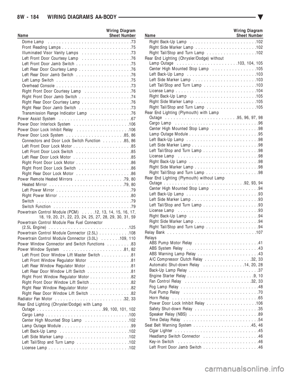
Wiring Diagram
Name Sheet Number
Dome Lamp ..............................73
Front Reading Lamps .........................75
Illuminated Visor Vanity Lamps ..................73
Left Front Door Courtesy Lamp ..................76
Left Front Door Jamb Switch ....................75
Left Rear Door Courtesy Lamp ...................76
Left Rear Door Jamb Switch ....................76
Left Lamp Switch ...........................75
Overhead Console ...........................73
Right Front Door Courtesy Lamp .................76
Right Front Door Jamb Switch ...................74
Right Rear Door Courtesy Lamp ..................76
Right Rear Door Jamb Switch ...................73
Transmission Range Indicator Lamp ...............76
Power Assist System ..........................67
Power Door Interlock System ....................106
Power Door Lock Inhibit Relay ...................106
Power Door Lock System .................... .85, 86
Connectors and Door Lock Switch Function ........85, 86
Left Front Door Lock Motor .....................85
Left Front Door Lock Switch ....................85
Left Rear Door Lock Motor .....................85
Right Front Door Lock Motor ....................86
Right Front Door Lock Switch ...................86
Right Rear Door Lock Motor ....................86
Power Remote Heated Mirrors ..................79, 80
Heated Mirror .......................... .79, 80
Left Power Mirror ...........................79
Right Power Mirror ..........................80
Switch ..................................79
Switch Function ............................79
Powertrain Control Module (PCM) .....12, 13, 14, 15, 16, 17,
18, 19, 20, 21, 22, 23, 24, 25, 27, 28, 29, 30, 31, 59
Powertrain Control Module Flex Fuel Connector (2.5L Engine) ............................ .125
Powertrain Control Module Connector (2.5L) ...........108
Powertrain Control Module Connector (3.0L) .......109, 110
Power Window Connector and Switch Functions .........83
Power Window System ..................... .81, 82
Left Front Door Window Lift Master Switch ...........81
Left Front Window Regulator Motor ...............81
Left Rear Window Regulator Motor ................81
Left Rear Door Window Lift Switch ................81
Right Front Window Regulator Motor ...............82
Right Front Door Window Lift Switch ...............82
Right Rear Window Regulator Motor ...............82
Right Rear Door Window Lift Switch ...............82
Radiator Fan Motor ........................ .32, 33
Rear End Lighting (Chrysler/Dodge) with Lamp Outage ....................... .99, 100, 101, 102
Cargo Lamp ............................. .100
Center High Mounted Stop Lamp ................102
Lamp Outage Module .........................99
Left Back-Up Lamp ........................ .102
Left Side Marker Lamp ...................... .102
Left Tail/Stop and Turn Lamp ...................102
License Lamp ............................ .102Wiring Diagram
Name Sheet Number
Right Back-Up Lamp ....................... .102
Right Side Marker Lamp ..................... .102
Right Tail/Stop and Turn Lamp ..................102
Rear End Lighting (Chrysler/Dodge) without Lamp Outage ..................... .103, 104, 105
Center High Mounted Stop Lamp ................105
Left Back-Up Lamp ........................ .103
Left Side Marker Lamp ...................... .103
Left Tail/Stop and Turn Lamp ...................103
License Lamp ............................ .104
Right Back-Up Lamp ....................... .105
Right Side Marker Lamp ..................... .105
Right Tail/Stop and Turn Lamp ..................105
Rear End Lighting (Plymouth) with Lamp Outage ......................... .95, 96, 97, 98
Cargo Lamp ..............................96
Center High Mounted Stop Lamp .................98
Lamp Outage Module .........................95
Left Back-Up Lamp ..........................98
Left Side Marker Lamp ........................98
Left Tail/Stop and Turn Lamp ....................98
License Lamp .............................98
Right Back-Up Lamp .........................98
Right Side Marker Lamp .......................98
Right Tail/Stop and Turn Lamp ...................98
Rear End Lighting (Plymouth) without Lamp Outage ............................ .92, 93, 94
Center High Mounted Stop Lamp .................94
Left Back-Up Lamp ..........................93
Left Side Marker Lamp ........................93
Left Tail/Stop and Turn Lamp ....................93
License Lamp .............................93
Right Back-Up Lamp .........................94
Right Side Marker Lamp .......................94
Right Tail/Stop and Turn Lamp ...................94
Relay Bank ............................... .107
Relays ABS Pump Motor Relay .......................41
ABS System Relay ..........................43
ABS Warning Lamp Relay ......................43
A/C Compressor Clutch Relay .................32, 33
Automatic Shut-down Relay ...............14, 20, 28
Back-Up Lamp Relay .........................37
Engine Starter Relay ........................9,10
Fan Control Relay ....................... .32, 33
Fog Lamp Relay ............................48
Fuel Pump Relay ...........................70
Horn Relay ...............................65
Power Door Lock Inhibit Relay ..................106
Safety Shut-down Relay .......................35
Speaker Relay (NBS) .........................89
Time Delay Relay ...........................54
Seat Belt Warning System .................... .45, 46
Cigar Lighter ..............................45
Headlamp Switch Connector ....................46
Key-in Switch .............................46
Left Front Door Jamb Switch ....................46
8W - 184 WIRING DIAGRAMS AA-BODY Ä
Page 936 of 2438
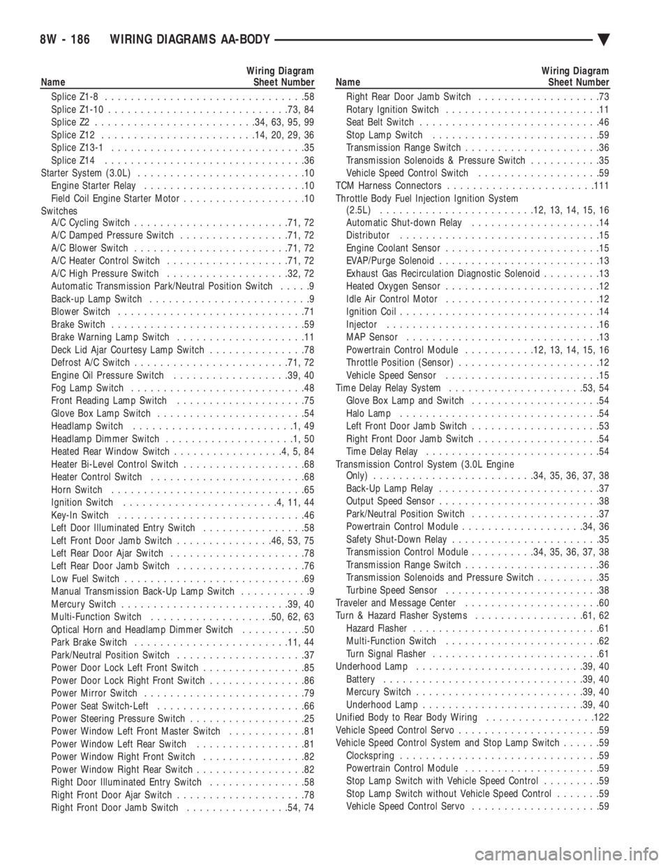
Wiring Diagram
Name Sheet Number
Splice Z1-8 ...............................58
Splice Z1-10 ........................... .73, 84
Splice Z2 ........................ .34, 63, 95, 99
Splice Z12 ....................... .14, 20, 29, 36
Splice Z13-1 ..............................35
Splice Z14 ...............................36
Starter System (3.0L) ..........................10
Engine Starter Relay .........................10
Field Coil Engine Starter Motor ...................10
Switches A/C Cycling Switch ....................... .71, 72
A/C Damped Pressure Switch .................71, 72
A/C Blower Switch ....................... .71, 72
A/C Heater Control Switch .................. .71, 72
A/C High Pressure Switch .................. .32, 72
Automatic Transmission Park/Neutral Position Switch .....9
Back-up Lamp Switch .........................9
Blower Switch .............................71
Brake Switch ..............................59
Brake Warning Lamp Switch ....................11
Deck Lid Ajar Courtesy Lamp Switch ...............78
Defrost A/C Switch ....................... .71, 72
Engine Oil Pressure Switch ..................39, 40
Fog Lamp Switch ...........................48
Front Reading Lamp Switch ....................75
Glove Box Lamp Switch .......................54
Headlamp Switch .........................1,49
Headlamp Dimmer Switch ....................1,50
Heated Rear Window Switch .................4,5,84
Heater Bi-Level Control Switch ...................68
Heater Control Switch ........................68
Horn Switch ..............................65
Ignition Switch ........................4,11,44
Key-In Switch .............................46
Left Door Illuminated Entry Switch ................58
Left Front Door Jamb Switch ...............46, 53, 75
Left Rear Door Ajar Switch .....................78
Left Rear Door Jamb Switch ....................76
Low Fuel Switch ............................69
Manual Transmission Back-Up Lamp Switch ...........9
Mercury Switch ......................... .39, 40
Multi-Function Switch .................. .50, 62, 63
Optical Horn and Headlamp Dimmer Switch ..........50
Park Brake Switch ....................... .11, 44
Park/Neutral Position Switch ....................37
Power Door Lock Left Front Switch ................85
Power Door Lock Right Front Switch ...............86
Power Mirror Switch .........................79
Power Seat Switch-Left .......................66
Power Steering Pressure Switch ..................25
Power Window Left Front Master Switch ............81
Power Window Left Rear Switch .................81
Power Window Right Front Switch ................82
Power Window Right Rear Switch .................82
Right Door Illuminated Entry Switch ...............58
Right Front Door Ajar Switch ....................78
Right Front Door Jamb Switch ................54, 74Wiring Diagram
Name Sheet Number
Right Rear Door Jamb Switch ...................73
Rotary Ignition Switch ........................11
Seat Belt Switch ............................46
Stop Lamp Switch ..........................59
Transmission Range Switch .....................36
Transmission Solenoids & Pressure Switch ...........35
Vehicle Speed Control Switch ...................59
TCM Harness Connectors ...................... .111
Throttle Body Fuel Injection Ignition System (2.5L) ....................... .12, 13, 14, 15, 16
Automatic Shut-down Relay ....................14
Distributor ...............................15
Engine Coolant Sensor ........................15
EVAP/Purge Solenoid .........................13
Exhaust Gas Recirculation Diagnostic Solenoid .........13
Heated Oxygen Sensor ........................12
Idle Air Control Motor ........................12
Ignition Coil ...............................14
Injector .................................16
MAP Sensor ..............................13
Powertrain Control Module ...........12, 13, 14, 15, 16
Throttle Position (Sensor) ......................12
Vehicle Speed Sensor ........................15
Time Delay Relay System .................... .53, 54
Glove Box Lamp and Switch ....................54
Halo Lamp ...............................54
Left Front Door Jamb Switch ....................53
Right Front Door Jamb Switch ...................54
Time Delay Relay ...........................54
Transmission Control System (3.0L Engine Only) ........................ .34, 35, 36, 37, 38
Back-Up Lamp Relay .........................37
Output Speed Sensor .........................38
Park/Neutral Position Switch ....................37
Powertrain Control Module .................. .34, 36
Safety Shut-Down Relay .......................35
Transmission Control Module ..........34, 35, 36, 37, 38
Transmission Range Switch .....................36
Transmission Solenoids and Pressure Switch ..........35
Turbine Speed Sensor ........................38
Traveler and Message Center .....................60
Turn & Hazard Flasher Systems .................61, 62
Hazard Flasher .............................61
Multi-Function Switch ........................62
Turn Signal Flasher ..........................61
Underhood Lamp ......................... .39, 40
Battery .............................. .39, 40
Mercury Switch ......................... .39, 40
Underhood Lamp ........................ .39, 40
Unified Body to Rear Body Wiring .................122
Vehicle Speed Control Servo ......................59
Vehicle Speed Control System and Stop Lamp Switch ......59
Clockspring ...............................59
Powertrain Control Module .....................59
Stop Lamp Switch with Vehicle Speed Control .........59
Stop Lamp Switch without Vehicle Speed Control .......59
Vehicle Speed Control Servo ....................59
8W - 186 WIRING DIAGRAMS AA-BODY Ä