air conditioning CHEVROLET DYNASTY 1993 User Guide
[x] Cancel search | Manufacturer: CHEVROLET, Model Year: 1993, Model line: DYNASTY, Model: CHEVROLET DYNASTY 1993Pages: 2438, PDF Size: 74.98 MB
Page 368 of 2438
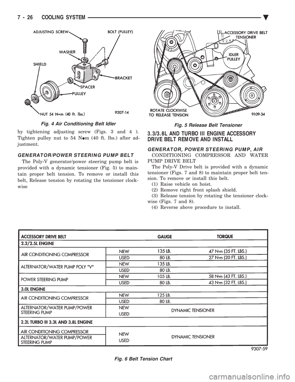
by tightening adjusting screw (Figs. 3 and 4 ).
Tighten pulley nut to 54 N Im (40 ft. lbs.) after ad-
justment.
GENERATOR/POWER STEERING PUMP BELT
The Poly-V generator/power steering pump belt is
provided with a dynamic tensioner (Fig. 5) to main-
tain proper belt tension. To remove or install this
belt, Release tension by rotating the tensioner clock-
wise
3.3/3.8L AND TURBO III ENGINE ACCESSORY
DRIVE BELT REMOVE AND INSTALL
GENERATOR, POWER STEERING PUMP, AIR
CONDITIONING COMPRESSOR AND WATER
PUMP DRIVE BELT The Poly-V Drive belt is provided with a dynamic
tensioner (Figs. 7 and 8) to maintain proper belt ten-
sion. To remove or install this belt. (1) Raise vehicle on hoist.
(2) Remove right front splash shield.
(3) Release tension by rotating the tensioner clock-
wise (Figs. 7 and 8). (4) Reverse above procedure to install.
Fig. 5 Release Belt Tensioner
Fig. 6 Belt Tension Chart
Fig. 4 Air Conditioning Belt Idler
7 - 26 COOLING SYSTEM Ä
Page 411 of 2438
GENERATOR INDEX
page page
General Information ........................ 9
Generator ReplacementÐ2.2L Turbo Engine (With 16 Valve Cylinder Head) ............. 10 Generator ReplacementÐ2.2L/2.5L Engine
...... 9
Generator ReplacementÐ3.0L Engine ......... 10
Generator ReplacementÐ3.3L/3.8L Engine ..... 11
GENERAL INFORMATION
This section will cover generator removal and instal-
lation only. Information covering generator on-vehicle
testing and diagnosis can be found in Group 8A,
Battery/Starting/Charging Systems Diagnostics. To
identify the generator, refer to the Generator Specifi-
cation chart at the rear of this section. These generators are not intended to be disas-
sembled for service. It must be replaced as an
assembly.
GENERATOR REPLACEMENTÐ2.2L/2.5L ENGINE
Removal and repositioning of A/C compressor (with-
out disconnecting refrigerant lines) is necessary on
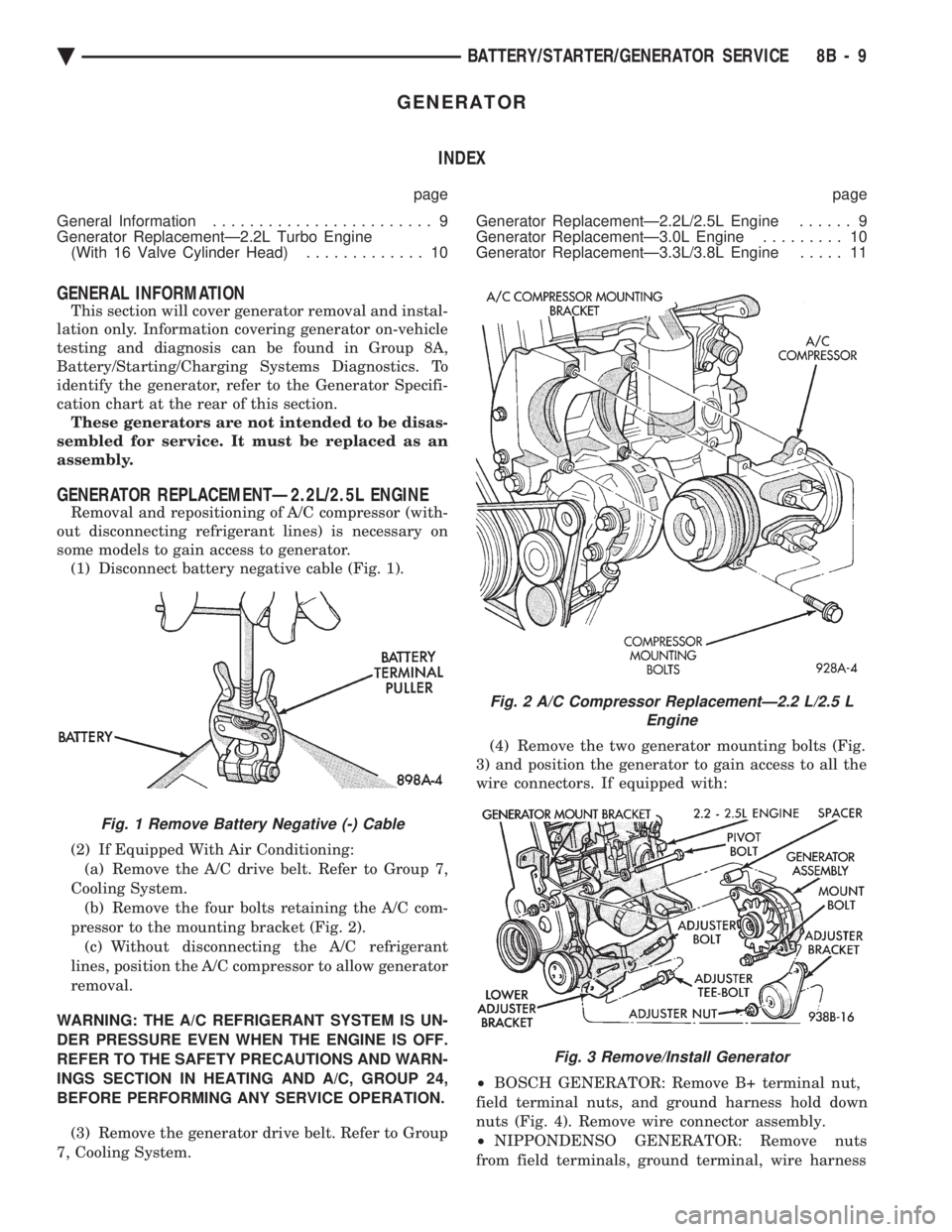
some models to gain access to generator. (1) Disconnect battery negative cable (Fig. 1).
(2) If Equipped With Air Conditioning:
(a) Remove the A/C drive belt. Refer to Group 7,
Cooling System. (b) Remove the four bolts retaining the A/C com-
pressor to the mounting bracket (Fig. 2). (c) Without disconnecting the A/C refrigerant
lines, position the A/C compressor to allow generator
removal.
WARNING: THE A/C REFRIGERANT SYSTEM IS UN-
DER PRESSURE EVEN WHEN THE ENGINE IS OFF.
REFER TO THE SAFETY PRECAUTIONS AND WARN-
INGS SECTION IN HEATING AND A/C, GROUP 24,
BEFORE PERFORMING ANY SERVICE OPERATION. (3) Remove the generator drive belt. Refer to Group
7, Cooling System. (4) Remove the two generator mounting bolts (Fig.
3) and position the generator to gain access to all the
wire connectors. If equipped with:
² BOSCH GENERATOR: Remove B+ terminal nut,
field terminal nuts, and ground harness hold down
nuts (Fig. 4). Remove wire connector assembly.
² NIPPONDENSO GENERATOR: Remove nuts
from field terminals, ground terminal, wire harness
Fig. 1 Remove Battery Negative (-) Cable
Fig. 2 A/C Compressor ReplacementÐ2.2 L/2.5 L Engine
Fig. 3 Remove/Install Generator
Ä BATTERY/STARTER/GENERATOR SERVICE 8B - 9
Page 412 of 2438
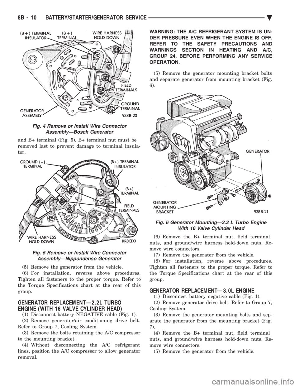
and B+ terminal (Fig. 5). B+ terminal nut must be
removed last to prevent damage to terminal insula-
tor. (5) Remove the generator from the vehicle.
(6) For installation, reverse above procedures.
Tighten all fasteners to the proper torque. Refer to
the Torque Specifications chart at the rear of this
group.
GENERATOR REPLACEMENTÐ2.2L TURBO
ENGINE (WITH 16 VALVE CYLINDER HEAD)
(1) Disconnect battery NEGATIVE cable (Fig. 1).
(2) Remove generator/air conditioning drive belt.
Refer to Group 7, Cooling System. (3) Remove the bolts retaining the A/C compressor
to the mounting bracket. (4) Without disconnecting the A/C refrigerant
lines, position the A/C compressor to allow generator
removal. WARNING: THE A/C REFRIGERANT SYSTEM IS UN-
DER PRESSURE EVEN WHEN THE ENGINE IS OFF.
REFER TO THE SAFETY PRECAUTIONS AND
WARNINGS SECTION IN HEATING AND A/C,
GROUP 24, BEFORE PERFORMING ANY SERVICE
OPERATION.
(5) Remove the generator mounting bracket bolts
and separate generator from mounting bracket (Fig.
6).
(6) Remove the B+ terminal nut, field terminal
nuts, and ground/wire harness hold-down nuts. Re-
move wire connectors. (7) Remove the generator from the vehicle.
(8) For installation, reverse above procedures.
Tighten all fasteners to the proper torque. Refer to
the Torque Specifications chart at the rear of this
group.
GENERATOR REPLACEMENTÐ3.0L ENGINE
(1) Disconnect battery negative cable (Fig. 1).
(2) Remove generator drive belt. Refer to Group 7,
Cooling System. (3) Remove the generator mounting bolts and sep-
arate the generator from the mounting bracket (Fig.
7). (4) Remove the B+ terminal nut, field terminal
nuts, and ground/wire harness hold-down nuts. Re-
move wire connectors. (5) Remove the generator from the vehicle.
Fig. 4 Remove or Install Wire Connector AssemblyÐBosch Generator
Fig. 5 Remove or Install Wire ConnectorAssemblyÐNippondenso Generator
Fig. 6 Generator MountingÐ2.2 L Turbo Engine With 16 Valve Cylinder Head
8B - 10 BATTERY/STARTER/GENERATOR SERVICE Ä
Page 513 of 2438
(3) Remove four screws from ash receiver/cup
holder housing. (4) For installation reverse above procedures.
AIR CONDITIONING CONTROLREPLACEMENT
(1) Disconnect battery negative cable and isolate
or remove fuse #2 prior to removing switch or wires
may short to ground. (2) Remove center bezel. Disconnect ash receiver
lamp socket. (3) Remove glove box assembly. Refer to Glove Box
Assembly Replacement. (4) Reach through glove box opening and discon-
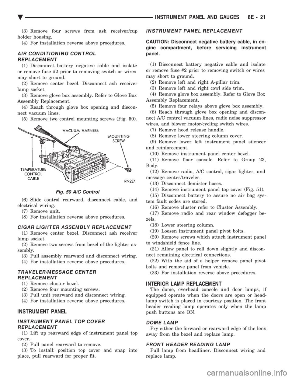
nect vacuum lines. (5) Remove two control mounting screws (Fig. 50).
(6) Slide control rearward, disconnect cable, and
electrical wiring. (7) Remove unit.
(8) For installation reverse above procedures.
CIGAR LIGHTER ASSEMBLY REPLACEMENT
(1) Remove center bezel. Disconnect ash receiver
lamp socket. (2) Remove two screws from bezel of the lighter as-
sembly. (3) Pull assembly rearward and disconnect wiring.
(4) For installation reverse above procedures.
TRAVELER/MESSAGE CENTER REPLACEMENT
(1) Remove cluster bezel.
(2) Remove four mounting screws.
(3) Pull unit rearward and disconnect wiring.
(4) For installation reverse above procedures.
INSTRUMENT PANEL
INSTRUMENT PANEL TOP COVER REPLACEMENT
(1) Lift up rearward edge of instrument panel top
cover. (2) Pull panel rearward to remove.
(3) To install: position top cover and snap into
place, pull rearward for proper fit.
INSTRUMENT PANEL REPLACEMENT
CAUTION: Disconnect negative battery cable, in en-
gine compartment, before servicing instrument
panel.
(1) Disconnect battery negative cable and isolate
or remove fuse #2 prior to removing switch or wires
may short to ground. (2) Remove left and right A-pillar trim.
(3) Remove left and right cowl side trim.
(4) Remove glove box assembly. Refer to Glove Box
Assembly Replacement. (5) Remove four relays above glove box assembly.
(6) Reach through glove box opening and discon-
nect A/C control vacuum lines, radio noise suppressor
wires, and blower motor/cycling switch wires. (7) Remove hood release handle.
(8) Remove lower steering column cover.
(9) Remove lower left instrument panel silencer
and reinforcement. (10) Remove instrument panel center bezel.
(11) Remove floor console. Refer to Group 23,
Body. (12) Remove radio, A/C control, cigar lighter, and
message center/traveler. (13) Disconnect demister hoses.
(14) Remove instrument panel top cover (Fig. 51).
(15) Disconnect battery to assure no air bag sys-
tem fault codes are stored. (16) Remove cluster refer to Cluster Assembly.
(17) Remove radio and rear window defogger be-
zels. (18) Lower steering column.
(19) Loosen instrument panel pivot bolts.
(20) Remove screws which attach instrument panel
to windshield fence line. (21) Allow panel to roll down slightly and discon-
nect remaining electrical connections. (22) With the aid of a helper remove panel pivot
bolts and remove panel from vehicle. (23) For installation reverse above procedures.
INTERIOR LAMP REPLACEMENT
The dome, overhead console and door lamps, if
equipped operate when the doors are open or head-
lamp switch is placed in courtesy position. The front
header reading lamp operates only when the lamp
push buttons are ON.
DOME LAMP
Pry either the forward or rearward edge of the lens
away from the bezel and replace lamp.
FRONT HEADER READING LAMP
Pull lamp from headliner. Disconnect wiring and
replace lamp.
Fig. 50 A/C Control
Ä INSTRUMENT PANEL AND GAUGES 8E - 21
Page 529 of 2438
CONDITION: US/METRIC MODES WILL NOT TOGGLE OR TRIP ODOMETER WILL NOTRESET
PROCEDURE
(1) Perform cluster self-diagnostics to determine if
push buttons are operational. (2) Refer to the Body Chassis Diagnostic Manual
to diagnose CCD Bus. The US/Metric toggle and trip
odometer reset are activated over the CCD Bus.
ODOMETER ADJUSTMENT
The odometer memory is no longer retained in the
cluster. This information is stored in the body con-
troller. Therefore, there is no adjustment procedure.
If the cluster is replaced odometer value will not
change. If the body controller is replaced the mileage
may be transferred using the DRB II. Refer to the
Body Chassis Diagnostic Manual for the procedure.
SWITCH AND PANEL COMPONENT SERVICE
MESSAGE CENTER REPLACEMENT
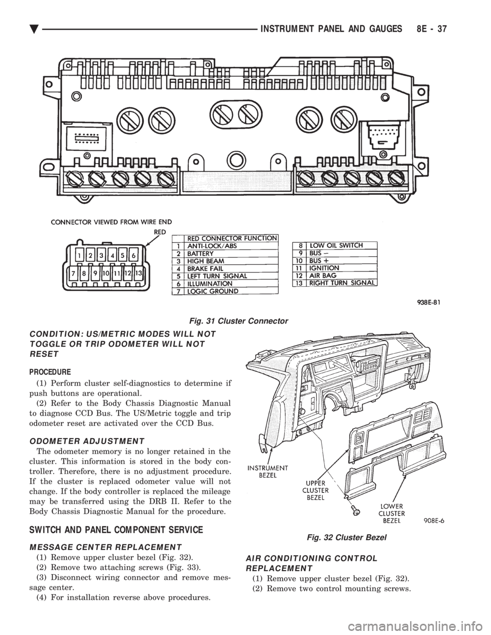
(1) Remove upper cluster bezel (Fig. 32).
(2) Remove two attaching screws (Fig. 33).
(3) Disconnect wiring connector and remove mes-
sage center. (4) For installation reverse above procedures.AIR CONDITIONING CONTROLREPLACEMENT
(1) Remove upper cluster bezel (Fig. 32).
(2) Remove two control mounting screws.
Fig. 31 Cluster Connector
Fig. 32 Cluster Bezel
Ä INSTRUMENT PANEL AND GAUGES 8E - 37
Page 546 of 2438
INSTALLATION (1) Latch switch linkage in the up position.
(2) Insert dimmer shaft into dimmer knob while
aligning switch in to switch pod assembly. (3) Install switch attaching screws.
(4) Unlatch linkage and install onto push buttons.
(5) Operate all switch modes for correct operation.
(6) Install turn signal switch.
(7) Reconnect wiring for turn signal switch, mak-
ing sure wire is properly clipped into position. (8) Place together the inner and outer bezels. In-
stall five inner switch pod panel screws and three
screws from underneath the switch pod. (9) Install turn signal lever by pushing straight
into switch assembly. (10) Install switch pod assembly.
LOWER STEERING COLUMN COVER REMOVAL
(1) Remove screws along top edge of cover.
(2) Remove screw at each lower corner of cover. (3) Remove cover from underneath over column
cover. (4) For installation reverse above procedures.
GLOVEBOX MODULE REMOVAL
(1) Disconnect battery negative cable and isolate
or remove fuse #26 prior to removing switch or wires
may short to ground. (2) Remove cowl side trim panel.
(3) Remove screws at right end of glovebox and
lower corners. (4) Open glovebox, remove light and disconnect
wiring. (5) Remove five screws along top of glovebox frame
and screw at each lower corner. (6) Remove glovebox assembly.
(7) For installation reverse above procedures.
CONCEALED HEADLAMP MODULE REMOVAL
(1) Remove left under panel silencer.
(2) Slide module off bayonet bracket while disen-
gaging spring retainer. (3) Disconnect wiring terminal.
(4) For installation reverse above procedures.
HOOD RELEASE REMOVE
(1) Remove lower column cover.
(2) Remove screws on fuse block and move aside.
(3) Remove screws on hood release assembly to re-
move. (4) For installation reverse above procedures.
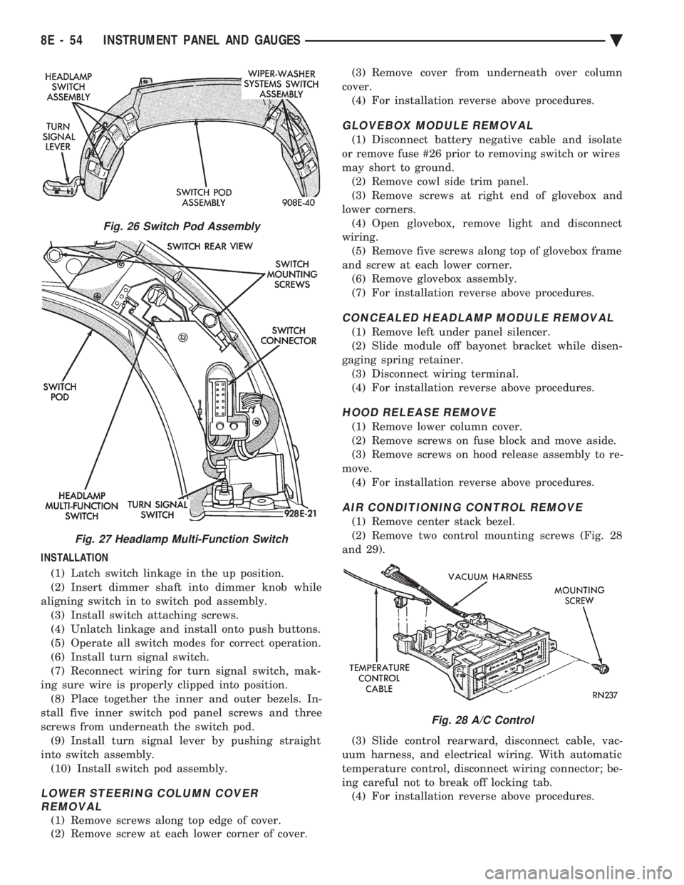
AIR CONDITIONING CONTROL REMOVE
(1) Remove center stack bezel.
(2) Remove two control mounting screws (Fig. 28
and 29).
(3) Slide control rearward, disconnect cable, vac-
uum harness, and electrical wiring. With automatic
temperature control, disconnect wiring connector; be-
ing careful not to break off locking tab. (4) For installation reverse above procedures.
Fig. 26 Switch Pod Assembly
Fig. 27 Headlamp Multi-Function Switch
Fig. 28 A/C Control
8E - 54 INSTRUMENT PANEL AND GAUGES Ä
Page 567 of 2438
AUDIO SYSTEM
CONTENTS
page page
ANTENNAS ............................ 20
COMPACT DISC PLAYER ................. 30 RADIOS
................................ 1
SPEAKERS ............................ 24
RADIOS INDEX
page page
Audio Diagnostic Test Procedures ............. 1
Description .............................. 1
Interference Elimination ..................... 1
Radio Removal AP Body Replacement ........ 19 Radio RemovalÐAA Body
.................. 18
Radio RemovalÐAC and AY Bodies .......... 18
Radio RemovalÐAG and AJ Bodies .......... 18
DESCRIPTION
For operation of the factory installed standard and
optional radios and the optional compact disc player,
refer to the Sound Systems Operating Instructions
Manual supplied with the vehicle. All vehicles are equipped with an Ignition-Off
Draw Connector which, is used when the vehicles are
originally shipped from the factory. This connector
which, is located near the battery, helps to prevent
battery discharge during storage. For specific connec-
tor type and location, refer to Group 8W, Wiring Di-
agrams. This connector is included in the radio memory cir-
cuitry and should be checked if the memory of time
or radio station programming is inoperative.
INTERFERENCE ELIMINATION
Some components are used on vehicles equipped
with a radio capacitor, to suppress radio frequency
interference/static. Capacitors are mounted in various locations, on the
generator either internal or external, internal to the
instrument cluster, and internal to the windshield
wiper motor. Ground straps are mounted from radio chassis to
instrument panel support structure, engine to cowl,
across engine mount on right hand side. On vehicles
with air conditioning there is a strap from evapora-
tor valve to cowl. These ground straps should be se-
curely tightened to assure good metal to metal
contact. Ground straps conduct very small high fre-
quency electrical signals to ground and require clean
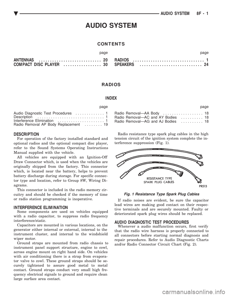
large surface area contact. Radio resistance type spark plug cables in the high
tension circuit of the ignition system complete the in-
terference suppression (Fig. 1).
If radio noises are evident, be sure the capacitor
lead wires are making good contact on their respec-
tive terminals and are securely mounted. Faulty or
deteriorated spark plug wires should be replaced.
AUDIO DIAGNOSTIC TEST PROCEDURES
Whenever a audio malfunction occurs, first verify
that the radio wire harness is properly connected to
all connectors before starting normal diagnosis and
repair procedures. Refer to Audio Diagnostic Charts
and/or Radio Connector Circuit Chart (Fig. 2).
Fig. 1 Resistance Type Spark Plug Cables
Ä AUDIO SYSTEM 8F - 1
Page 931 of 2438
WIRING DIAGRAMS AA-BODY
INDEX
Wiring Diagram
Name Sheet Number
Airbag System ...............................47
Clockspring ...............................47
Diagnostic Module ..........................47
Interface Grommet ..........................47
Sensor-Left ...............................47
Sensor-Right ..............................47
Squibb ..................................47
Air Conditioning Compressor ...................32, 33
Air Conditioning System (2.5L Engine) ...............71
A/C Cycling Switch ..........................71
Blower Motor ..............................71
Blower Switch .............................71
Control Switch .............................71
Damped Pressure Switch ......................71
Defrost Switch .............................71
Illumination Lamp ...........................71
Resistor .................................71
Air Conditioning System (3.0L Engine) ...............72
A/C Switch ...............................72
Blower Motor ..............................72
Blower Switch .............................72
Control Switch .............................72
Damped Pressure Switch ......................72
Defrost Switch .............................72
High Pressure Switch ........................72
Illumination Lamp ...........................72
Resistor .................................72
Anti-Lock Brake System .................41, 42, 43, 44
ABS Pump Motor Relay .......................41
ABS System Relay ..........................43
ABS Warning Lamp Relay ......................43
Brake Switch ..............................44
Controller ....................... .41, 42, 43, 44
Hydraulic Modulator .........................41
Ignition Switch .............................44
Park Brake Switch ...........................44
Wheel Sensors .............................42
Ash Receiver Lamp ...........................52
Automatic Shut-down Relay .................14, 20, 28
Automatic Transmission Park/Neutral Position and Back-Up Lamp Switch ...............................9
Back-Up Lamp Switch ..........................9
Battery ............................1,5,7,39,40
Blower Motor-A/C ............................71
Blower Motor-Heater ...........................71
Brake Switch ...............................44
Brake Warning Lamp Switch ......................11
Bulkhead Disconnect (50-Way) ................112, 113
Center High Mounted Stop Lamp ..........94, 98, 102, 105
Charging System (2.5L) ........................5,6
Battery ...................................5
Generator .................................6Wiring Diagram
Name Sheet Number
Heated Rear Window Switch .....................5
Charging System (3.0L) ........................7,8
Battery ....................................7
Generator .................................8
Ignition Off-Draw Connector .....................7
Cigar Lighter ................................45
Cigar Lighter Lamp ............................52
Circuit Breaker (30 Amp) Fuseblock Cavity #10 .......67, 82
Circuit Breaker (30 Amp) Fuseblock Cavity #13 . . .2, 66, 67, 86
Clockspring ............................. .47, 59
Cluster Printed Circuit Board .................119, 120
Cluster Printed Circuit Board Connectors .............118
Courtesy Lamps .............................76
Daytime Running Light Module ....................57
Deck Lid Ajar Switch ..........................78
Dimmer Switch-Headlamp .....................1,50
Distributor ......................... .15, 21, 22, 27
EGR Solenoid ...............................24
Electrically Heated Rear Window ...................84
Heated Rear Window .........................84
Switch ..................................84
Timer ...................................84
Electronically Tuned Stereo Radio without Name Brand Speakers ................................87
Electronically Tuned Stereo Radio with Name Brand Speakers ................................89
Speaker Choke .............................89
Speaker Relay .............................89
Electronic Cluster ........................... .121
Engine Coolant Sensor ................... .15, 21, 27
Engine Oil and Temperature Warning System (2.5L) .......39
Engine Oil and Temperature Warning System (3.0L) .......40
Engine Oil Pressure Switch/Sending Unit ...........39, 40
Engine Temperature Sending Unit ................39, 40
Engine Starter System (2.5L Engine & 3.0L ATX) .......9,10
Automatic Transmission Park/Neutral Position Switch .....9
Backup Lamp Switch ..........................9
EMCC Solenoid .............................9
Engine Starter Relay ..........................9
Manual Transmission Back-Up Lamp Switch ...........9
Permanent Magnet Engine Starter Motor .............9
Engine Temperature Sending Unit ................39, 40
Exhaust Gas Recirculation Diagnostic Solenoid ........13, 24
Fan Control System with A/C and Heater System (2.5L) ....32
A/C Compressor ............................32
A/C Compressor Clutch Relay ...................32
A/C High Pressure Switch ......................32
Fan Control Relay ...........................32
Radiator Fan Motor ..........................32
Fan Control System with A/C and Heater System (3.0L) ....33
A/C Conditioning Compressor ...................33
A/C Compressor Clutch Relay ...................33
Ä WIRING DIAGRAMS AA-BODY 8W - 181
Page 1063 of 2438
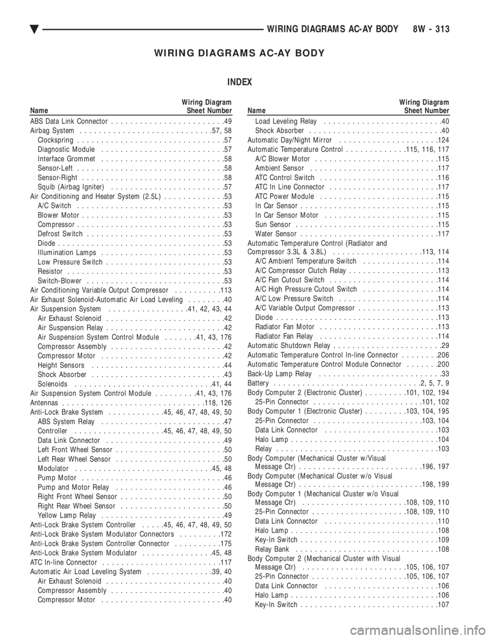
WIRING DIAGRAMS AC-AY BODY INDEX
Wiring Diagram
Name Sheet Number
ABS Data Link Connector ........................49
Airbag System ........................... .57, 58
Clockspring ...............................57
Diagnostic Module ..........................57
Interface Grommet ..........................58
Sensor-Left ...............................58
Sensor-Right ..............................58
Squib (Airbag Igniter) ........................57
Air Conditioning and Heater System (2.5L) .............53
A/C Switch ...............................53
Blower Motor ..............................53
Compressor ...............................53
Defrost Switch .............................53
Diode ...................................53
Illumination Lamps ..........................53
Low Pressure Switch .........................53
Resistor .................................53
Switch-Blower .............................53
Air Conditioning Variable Output Compressor ..........113
Air Exhaust Solenoid-Automatic Air Load Leveling ........40
Air Suspension System .................41, 42, 43, 44
Air Exhaust Solenoid .........................42
Air Suspension Relay .........................42
Air Suspension System Control Module .......41, 43, 176
Compressor Assembly ........................42
Compressor Motor ..........................42
Height Sensors ............................44
Shock Absorber ............................43
Solenoids ............................ .41, 44
Air Suspension System Control Module .........41, 43, 176
Antennas ............................. .118, 126
Anti-Lock Brake System ............45, 46, 47, 48, 49, 50
ABS System Relay ..........................47
Controller .................. .45, 46, 47, 48, 49, 50
Data Link Connector .........................49
Left Front Wheel Sensor .......................50
Left Rear Wheel Sensor .......................50
Modulator ............................ .45, 48
Pump Motor ..............................46
Pump and Motor Relay .......................46
Right Front Wheel Sensor ......................50
Right Rear Wheel Sensor ......................50
Yellow Lamp Relay ..........................49
Anti-Lock Brake System Controller .....45, 46, 47, 48, 49, 50
Anti-Lock Brake System Modulator Connectors .........172
Anti-Lock Brake System Controller Connector ..........175
Anti-Lock Brake System Modulator ...............45, 48
ATC In-line Connector ........................ .117
Automatic Air Load Leveling System ..............39, 40
Air Exhaust Solenoid .........................40
Compressor Assembly ........................40
Compressor Motor ..........................40Wiring Diagram
Name Sheet Number
Load Leveling Relay .........................40
Shock Absorber ............................40
Automatic Day/Night Mirror .................... .124
Automatic Temperature Control .............115, 116, 117
A/C Blower Motor ......................... .115
Ambient Sensor .......................... .117
ATC Control Switch ........................ .116
ATC In Line Connector ...................... .117
ATC Power Module ........................ .115
In Car Senso r............................ .115
In Car Sensor Motor ....................... .115
Sun Sensor ............................. .115
Water Sensor ............................ .117
Automatic Temperature Control (Radiator and
Compressor 3.3L & 3.8L) .................. .113, 114
A/C Ambient Temperature Switch ................114
A/C Compressor Clutch Relay ...................113
A/C Fan Cutout Switch ...................... .114
A/C High Pressure Cutout Switch ................114
A/C Low Pressure Switch .................... .114
A/C Variable Output Compressor .................113
Diode ................................. .113
Radiator Fan Motor ........................ .113
Radiator Fan Relay ........................ .114
Automatic Shutdown Relay .......................29
Automatic Temperature Control In-line Connector ........206
Automatic Temperature Control Module Connector .......200
Back-Up Lamp Relay ..........................33
Battery ...............................2,5,7,9
Body Computer 2 (Electronic Cluster) .........101, 102, 194
25-Pin Connector ...................... .101, 102
Body Computer 1 (Electronic Cluster) .........103, 104, 195
25-Pin Connector ...................... .103, 104
Data Link Connector ....................... .103
Halo Lamp .............................. .104
Relay ................................. .103
Body Computer (Mechanical Cluster w/Visual Message Ctr) ......................... .196, 197
Body Computer (Mechanical Cluster w/o Visual Message Ctr) ......................... .198, 199
Body Computer 1 (Mechanical Cluster w/o Visual Message Ctr) ..................... .108, 109, 110
25-Pin Connector ................... .108, 109, 110
Data Link Connector ....................... .110
Halo Lamp .............................. .108
Key-In Switch ............................ .109
Relay Bank ............................. .108
Body Computer 2 (Mechanical Cluster with Visual Message Ctr) ..................... .105, 106, 107
25-Pin Connector ................... .105, 106, 107
Data Link Connector ....................... .106
Halo Lamp .............................. .106
Key-In Switch ............................ .107
Ä WIRING DIAGRAMS AC-AY BODY 8W - 313
Page 1065 of 2438
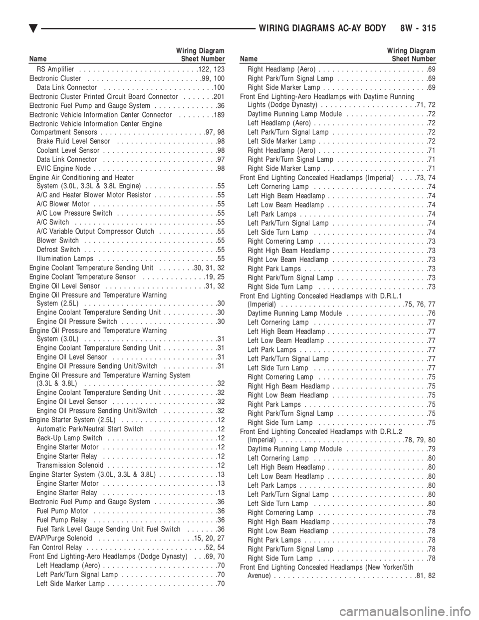
Wiring Diagram
Name Sheet Number
RS Amplifier ......................... .122, 123
Electronic Cluster ........................ .99, 100
Data Link Connector ....................... .100
Electronic Cluster Printed Circuit Board Connector .......201
Electronic Fuel Pump and Gauge System ..............36
Electronic Vehicle Information Center Connector ........189
Electronic Vehicle Information Center Engine Compartment Sensors ...................... .97, 98
Brake Fluid Level Sensor ......................98
Coolant Level Sensor .........................98
Data Link Connector .........................97
EVIC Engine Node ...........................98
Engine Air Conditioning and Heater System (3.0L, 3.3L & 3.8L Engine) ................55
A/C and Heater Blower Motor Resistor ..............55
A/C Blower Motor ...........................55
A/C Low Pressure Switch ......................55
A/C Switch ...............................55
A/C Variable Output Compressor Clutch .............55
Blower Switch .............................55
Defrost Switch .............................55
Illumination Lamps ..........................55
Engine Coolant Temperature Sending Unit ........30, 31, 32
Engine Coolant Temperature Sensor ..............19, 25
Engine Oil Level Sensor ..................... .31, 32
Engine Oil Pressure and Temperature Warning System (2.5L) .............................30
Engine Coolant Temperature Sending Unit ............30
Engine Oil Pressure Switch .....................30
Engine Oil Pressure and Temperature Warning System (3.0L) .............................31
Engine Coolant Temperature Sending Unit ............31
Engine Oil Level Sensor .......................31
Engine Oil Pressure Sending Unit/Switch ............31
Engine Oil Pressure and Temperature Warning System (3.3L & 3.8L) .............................32
Engine Coolant Temperature Sending Unit ............32
Engine Oil Level Sensor .......................32
Engine Oil Pressure Sending Unit/Switch ............32
Engine Starter System (2.5L) .....................12
Automatic Park/Neutral Start Switch ...............12
Back-Up Lamp Switch ........................12
Engine Starter Motor .........................12
Engine Starter Relay .........................12
Transmission Solenoid ........................12
Engine Starter System (3.0L, 3.3L & 3.8L) .............13
Engine Starter Motor .........................13
Engine Starter Relay .........................13
Electronic Fuel Pump and Gauge System ..............36
Fuel Pump Motor ...........................36
Fuel Pump Relay ...........................36
Fuel Tank Level Gauge Sending Unit Fuel Switch .......36
EVAP/Purge Solenoid .................... .15, 20, 27
Fan Control Relay ......................... .52, 54
Front End Lighting-Aero Headlamps (Dodge Dynasty) . . .69, 70 Left Headlamp (Aero) .........................70
Left Park/Turn Signal Lamp .....................70
Left Side Marker Lamp ........................70Wiring Diagram
Name Sheet Number
Right Headlamp (Aero) ........................69
Right Park/Turn Signal Lamp ....................69
Right Side Marker Lamp .......................69
Front End Lighting-Aero Headlamps with Daytime Running Lights (Dodge Dynasty) .................... .71, 72
Daytime Running Lamp Module ..................72
Left Headlamp (Aero) .........................72
Left Park/Turn Signal Lamp .....................72
Left Side Marker Lamp ........................72
Right Headlamp (Aero) ........................71
Right Park/Turn Signal Lamp ....................71
Right Side Marker Lamp .......................71
Front End Lighting Concealed Headlamps (Imperial) . . . .73, 74
Left Cornering Lamp .........................74
Left High Beam Headlamp ......................74
Left Low Beam Headlamp ......................74
Left Park Lamps ............................74
Left Park/Turn Signal Lamp .....................74
Left Side Turn Lamp .........................74
Right Cornering Lamp ........................73
Right High Beam Headlamp .....................73
Right Low Beam Headlamp .....................73
Right Park Lamps ...........................73
Right Park/Turn Signal Lamp ....................73
Right Side Turn Lamp ........................73
Front End Lighting Concealed Headlamps with D.R.L.1 (Imperial) .......................... .75, 76, 77
Daytime Running Lamp Module ..................76
Left Cornering Lamp .........................77
Left High Beam Headlamp ......................77
Left Low Beam Headlamp ......................77
Left Park Lamps ............................77
Left Park/Turn Signal Lamp .....................77
Left Side Turn Lamp .........................77
Right Cornering Lamp ........................75
Right High Beam Headlamp .....................75
Right Low Beam Headlamp .....................75
Right Park Lamps ...........................75
Right Park/Turn Signal Lamp ....................75
Right Side Turn Lamp ........................75
Front End Lighting Concealed Headlamps with D.R.L.2 (Imperial) .......................... .78, 79, 80
Daytime Running Lamp Module ..................79
Left Cornering Lamp .........................80
Left High Beam Headlamp ......................80
Left Low Beam Headlamp ......................80
Left Park Lamps ............................80
Left Park/Turn Signal Lamp .....................80
Left Side Turn Lamp .........................80
Right Cornering Lamp ........................78
Right High Beam Headlamp .....................78
Right Low Beam Headlamp .....................78
Right Park Lamps ...........................78
Right Park/Turn Signal Lamp ....................78
Right Side Turn Lamp ........................78
Front End Lighting Concealed Headlamps (New Yorker/5th Avenue) .............................. .81, 82
Ä WIRING DIAGRAMS AC-AY BODY 8W - 315