oil change CHEVROLET DYNASTY 1993 User Guide
[x] Cancel search | Manufacturer: CHEVROLET, Model Year: 1993, Model line: DYNASTY, Model: CHEVROLET DYNASTY 1993Pages: 2438, PDF Size: 74.98 MB
Page 171 of 2438
If old springs have overheated or are damaged, re-
place. Overheating indications are paint discoloration
or distorted end coils. Varga brake springs are not
painted but overheating of the brake springs will be
noted by any Blueing of the springs.
BRAKE SHOE INSTALLATION
Lubricate the eight shoe contact areas on the sup-
port plate and anchor using Mopar Multi-Purpose
Lubricant or equivalent (Fig. 11).
KELSEY HAYES REASSEMBLE
Assemble the park brake lever and wave washer to
the new replacement shoe (Fig. 9). Attach upper return spring between the two new
shoe assemblies. Apply a small amount of Mopar Multi-Purpose Lu-
bricant or equivalent to the automatic adjuster screw
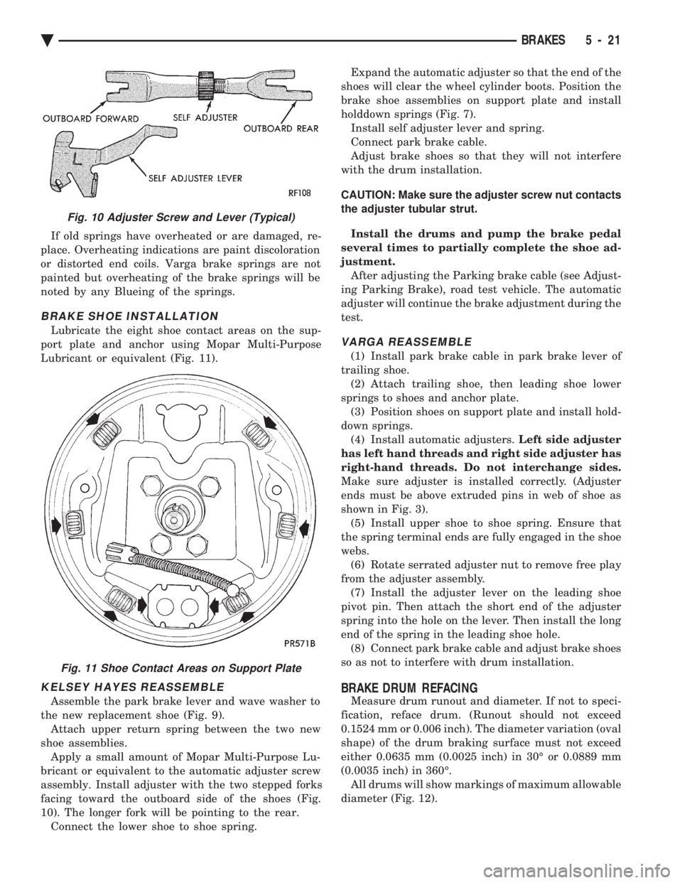
assembly. Install adjuster with the two stepped forks
facing toward the outboard side of the shoes (Fig.
10). The longer fork will be pointing to the rear. Connect the lower shoe to shoe spring. Expand the automatic adjuster so that the end of the
shoes will clear the wheel cylinder boots. Position the
brake shoe assemblies on support plate and install
holddown springs (Fig. 7). Install self adjuster lever and spring.
Connect park brake cable.
Adjust brake shoes so that they will not interfere
with the drum installation.
CAUTION: Make sure the adjuster screw nut contacts
the adjuster tubular strut.
Install the drums and pump the brake pedal
several times to partially complete the shoe ad-
justment. After adjusting the Parking brake cable (see Adjust-
ing Parking Brake), road test vehicle. The automatic
adjuster will continue the brake adjustment during the
test.
VARGA REASSEMBLE
(1) Install park brake cable in park brake lever of
trailing shoe. (2) Attach trailing shoe, then leading shoe lower
springs to shoes and anchor plate. (3) Position shoes on support plate and install hold-
down springs. (4) Install automatic adjusters. Left side adjuster
has left hand threads and right side adjuster has
right-hand threads. Do not interchange sides.
Make sure adjuster is installed correctly. (Adjuster
ends must be above extruded pins in web of shoe as
shown in Fig. 3). (5) Install upper shoe to shoe spring. Ensure that
the spring terminal ends are fully engaged in the shoe
webs. (6) Rotate serrated adjuster nut to remove free play
from the adjuster assembly. (7) Install the adjuster lever on the leading shoe
pivot pin. Then attach the short end of the adjuster
spring into the hole on the lever. Then install the long
end of the spring in the leading shoe hole. (8) Connect park brake cable and adjust brake shoes
so as not to interfere with drum installation.
BRAKE DRUM REFACING
Measure drum runout and diameter. If not to speci-
fication, reface drum. (Runout should not exceed
0.1524 mm or 0.006 inch). The diameter variation (oval
shape) of the drum braking surface must not exceed
either 0.0635 mm (0.0025 inch) in 30É or 0.0889 mm
(0.0035 inch) in 360É. All drums will show markings of maximum allowable
diameter (Fig. 12).
Fig. 10 Adjuster Screw and Lever (Typical)
Fig. 11 Shoe Contact Areas on Support Plate
Ä BRAKES 5 - 21
Page 243 of 2438
DRIVE-OFF CYCLE
The DRIVE-OFF CYCLE takes place when the ve-
hicle reaches about 3 miles per hour the first time af-
ter an ignition reset. During this test, the modulator
solenoid valves are activated briefly to test their
function. The DRIVE-OFF CYCLE will be bypassed
if you drive-off with the service brake pedal de-
pressed.
LATCHING VERSUS NON-LATCHING FAULTS
Some faults detected by the (CAB) are latching.
The fault is latched and (ABS) function is disabled
until the ignition switch is reset (turned OFF/ON).
Thus (ABS) function is disabled even if the original
fault has disappeared during the ignition cycle in
which it occurred. Other faults are non-latching; any
warning lights that are turned on are only on as long
as the fault condition exists. As soon as the condition
goes away. The Amber Anti-Lock Warning Light is
turned off. Although a fault code will be set in most
cases. (Example:low accumulator fault will not be
stored for a time of 2 minutes after the fault is de-
tected).
BENDIX ABS SYSTEMS DIAGNOSTICS
The Bendix Anti-Lock 10 Brake System diagnos-
tics. Beyond the basic mechanical diagnostics, sys-
tems and components covered earlier in this section,
is accomplished by using the DRB II diagnostic
tester. See testing procedures outlined in the Bendix
Anti-Lock 10 Diagnostics Manual for the 1993 M.Y. Please reference the above mentioned manual. For
any further diagnostic service procedures that are re-
quired on the Bendix Anti-Lock 10 Brake System, re-
quiring the use of the DRB II diagnostic tester.
ON CAR HYDRAULIC ABS COMPONENT SERVICE
WARNING: FAILURE TO FULLY DE-PRESSURIZE
THE HYDRAULIC ACCUMULATOR BEFORE PER-
FORMING HYDRAULIC SYSTEM SERVICE OPERA-
TIONS. COULD RESULT IN INJURY TO SERVICE
PERSONNEL AND OR DAMAGE TO PAINTED SUR-
FACES. SEE SECTION 2 FOR ADDITIONAL WARN-
INGS AND CAUTIONS.
GENERAL SERVICE PRECAUTIONS
The following are general precautions that should
be observed when servicing the Anti-Lock Brake Sys-
tem and/or other vehicle systems. Failure to observe
these precautions may result in Anti-Lock brake sys-
tem damage. If welding work is to be performed on the vehicle,
using an electric arc welder, the (CAB) connector
should be disconnected during the welding operation. The (CAB) or hydraulic assembly connector should
never be connected or disconnected with the ignition
switch in the ONposition.
Many components of the Anti-Lock brake system are
not serviceable and must be replaced as an assembly.
Do not attempt to disassemble any component
that is not designed to be a serviced component.
DE-PRESSURIZING HYDRAULIC ACCUMULA- TOR
The pump/motor assembly will keep the hydraulic
accumulator charged to approximately 11,032 and
13,790 kPa (1600 and 2000 psi) any time that the
ignition is in the ON position. The pump/motor assem-
bly cannot run if the ignition is off or if either battery
cable is disconnected. Unless otherwise specified, the hydraulic accumula-
tor should be de-pressurized before disassembling any
portion of the hydraulic system. The following proce-
dure should be used to relieve the pressure in the
hydraulic accumulator: (1) With ignition off, or either battery cable discon-
nected, pump the brake pedal a minimum of 40 times,
using approximately 222 N (50 lbs.) pedal force. A
noticeable change in pedal feel will occur, when the
accumulator is discharged. (2) When a definite increase in pedal effort is felt,
pump pedal a few additional times. This will insure
removal of all hydraulic pressure from the brake sys-
tem.
CHECKING BRAKE FLUID LEVEL
CAUTION: Use only brake fluid conforming to DOT 3
specifications such as Mopar Tor Equivalent. Do not
use any fluid in the brake hydraulic system, which
contains a petroleum base. Do not use a container
which has been used for petroleum based fluids or a
container that is wet with water. Petroleum based
fluids will cause swelling and distortion of rubber
parts in the hydraulic brake system and water will mix
with brake fluid, lowering the fluid boiling point. Keep
all brake fluid containers tightly capped to prevent
contamination.
The hydraulic assembly is equipped with a plastic
fluid reservoir, with a filter/strainer located in the filler
neck of each reservoir section. The Anti-Lock brake system requires that the hy-
draulic accumulator be de-pressurized when checking
the fluid level. To check the brake fluid level, the
following procedure should be used: (1) With the ignition off, de-pressurize the hydraulic
accumulator by applying the brake pedal approxi-
mately 40 times, using a pedal force of approximately
220 N (50 lbs.). A noticeable change in pedal feel will
occur when the accumulator is de-
Ä ANTI-LOCK 10 BRAKE SYSTEM 5 - 93
Page 357 of 2438
-37ÉC (-35ÉF) to -59ÉC (-50ÉF). If it looses color or
becomes contaminated, drain, flush, and replace with
fresh properly mixed solution.
SERVICE
Coolant should be changed at 52,500 miles or three
years, whichever occurs first, then every two years or
30,000 miles.
ROUTINE LEVEL CHECK
Do not remove radiator cap for routine coolant
level inspections. The coolant reserve system provides a quick visual
method for determining the coolant level without re-
moving the radiator cap. Simply observe, with the
engine idling and warmed up to normal operating
temperature, that the level of the coolant in the reserve
tank (Figs. 5 and 6) is between the minimum and
maximum marks.
ADDING ADDITIONAL COOLANT
The radiator cap should not be removed. When
additional coolant is needed to maintain this level, it
should be added to the coolant reserve tank. Use only
50/50 concentration of ethylene glycol type antifreeze
and water.
SERVICE COOLANT LEVEL
The cooling system is closed and designed to main-
tain coolant level to the top of the radiator. When servicing requires a coolant level check in the
radiator, the engine must be offand notunder pres-
sure. Drain several ounces of coolant from the radiator
drain cock while observing the Coolant Recovery Sys-
tem (CRS) Tank. Coolant level in the CRS tank should
drop slightly. Then remove the radiator cap. The radia-
tor should be full to the top. If not, and the coolant level
in the CRS tank is at the MIN mark there is a air leak
in the CRS system. Check hose or hose connections to
the CRS tank, radiator filler neck or the pressure cap
seal to the radiator filler neck for leaks.
LOW COOLANT LEVEL AERATION
Low coolant level in a cross flow radiator will equal-
ize in both tanks with engine off. With engine at
running operating temperature the high pressure inlet
tank runs full and the low pressure outlet tank drops.
If this level drops below the top of the transmission oil
cooler, air will be sucked into the water pump:
² Transmission oil will become hotter.
² High reading shown on the temperature gauge.
² Air in the coolant will also cause loss of flow through
the heater.
² Exhaust gas leaks into the coolant can also cause the
same problems.
DEAERATION
Air can only be removed from the system by gather-
ing under the pressure cap. On the next heat up it will
be pushed past the pressure cap into the CRS tank by
thermal expansion of the coolant. It then escapes to the
atmosphere in the CRS tank and is replaced with solid
coolant on cool down.
COOLING SYSTEM DRAIN, CLEAN, FLUSH AND
REFILL
Drain, flush, and fill the cooling system at the
mileage or time intervals specified in the Maintenance
Schedule in this Group. If the solution is dirty or rusty
or contains a considerable amount of sediment, clean
and flush with a reliable cooling system cleaner. Care
should be taken in disposing of the used engine coolant
from your vehicle. Check governmental regulations for
disposal of used engine coolant.
DRAINING
To drain cooling system move temperature selector
for heater to full heat with engine running (to provide
vacuum for actuation). Without removing radiator
pressure cap and with system not under pres-
sure, Shut engine off and open draincock. The coolant
reserve tank (Fig. 5) should empty first, then remove
radiator pressure cap. (if not, see Testing Cooling
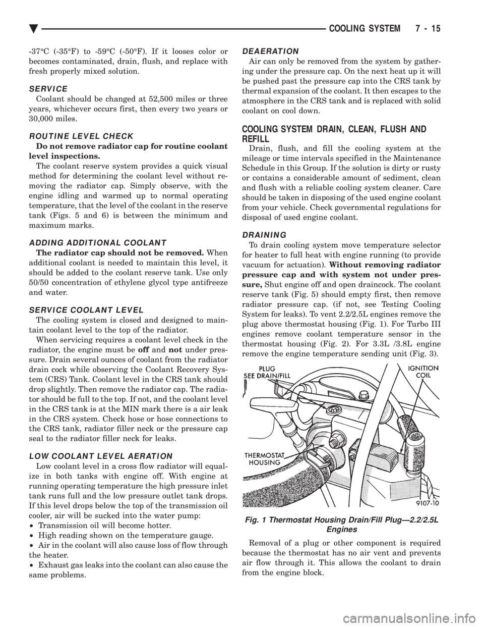
System for leaks). To vent 2.2/2.5L engines remove the
plug above thermostat housing (Fig. 1). For Turbo III
engines remove coolant temperature sensor in the
thermostat housing (Fig. 2). For 3.3L /3.8L engine
remove the engine temperature sending unit (Fig. 3).
Removal of a plug or other component is required
because the thermostat has no air vent and prevents
air flow through it. This allows the coolant to drain
from the engine block.
Fig. 1 Thermostat Housing Drain/Fill PlugÐ2.2/2.5L Engines
Ä COOLING SYSTEM 7 - 15
Page 445 of 2438
When testing secondary cables for punctures and
cracks with an oscilloscope follow the equipment
manufacturers instructions. If an oscilloscope is not available, secondary cables
can be tested as follows:
CAUTION: Do not leave any one spark plug cable
disconnected any longer than necessary during test-
ing. Excessive heat could damage the catalytic con-
verter. Total test time must not exceed ten minutes.
(a) With the engine not running, connect one end
of a test probe to a good ground. Use a probe made of
insulated wire with insulated alligator clips on each
end. (b) With engine running, move test probe along
entire length of all cables (approximately 0 to 1/8
inch gap). If punctures or cracks are present there
will be a noticeable spark jump from the faulty area
to the probe. Check the coil cable the same way.
Replace cracked, leaking or faulty cables.
When replacing cables, install the new high
tension cable and nipple assembly over cap or
coil tower. When entering the terminal into the
tower, push lightly, then pinch the large diam-
eter of nipple to release air trapped between the
nipple and tower. Continue pushing on the cable
and nipple until cables are properly seated in the
cap towers. A snap should be heard as terminal
goes into place. Use the same procedure to install cable in coil tower.
Wipe the spark plug insulator clean before reinstalling
cable and cover. Use the following procedure when removing the high
tension cable from the spark plug. First, remove the
cable from the retaining bracket. Then grasp the ter-
minal as close as possible to the spark plug. Rotate the
cover and pull the cable straight back. Pulling on the
cable itself will damage the conductor and termi-
nal connection. Do not use pliers and do not pull
the cable at an angle. Doing so will damage the
insulation, cable terminal or the spark plug in-
sulator. Wipe spark plug insulator clean before
reinstalling cable and cover. Resistance type cable is identified by the words
Electronic Suppression printed on the cable jacket.
Use an ohmmeter to check resistance type cable for
open circuits, loose terminals or high resistance as
follows: (a) Remove cable from spark plug.
(b) Lift distributor cap from distributor with
cables intact. Do not remove cables from cap. The
cables must be removed from the spark plugs. (c) Connect the ohmmeter between spark plug end
terminal and the corresponding electrode inside the
cap, make sure ohmmeter probes are in good contact.
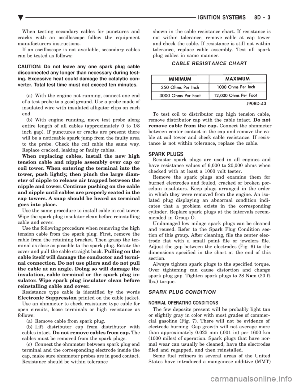
Resistance should be within tolerance shown in the cable resistance chart. If resistance is
not within tolerance, remove cable at cap tower
and check the cable. If resistance is still not within
tolerance, replace cable assembly. Test all spark
plug cables in same manner.
To test coil to distributor cap high tension cable,
remove distributor cap with the cable intact. Do not
remove cable from the cap. Connect the ohmmeter
between center contact in the cap and remove the ca-
ble at coil tower and check cable resistance. If resis-
tance is not within tolerance, replace the cable.
SPARK PLUGS
Resistor spark plugs are used in all engines and
have resistance values of 6,000 to 20,000 ohms when
checked with at least a 1000 volt tester. Remove the spark plugs and examine them for
burned electrodes and fouled, cracked or broken por-
celain insulators. Keep plugs arranged in the order
in which they were removed from the engine. An iso-
lated plug displaying an abnormal condition indi-
cates that a problem exists in the corresponding
cylinder. Replace spark plugs at the intervals recom-
mended in Group O. Undamaged low milage spark plugs can be cleaned
and reused. Refer to the Spark Plug Condition sec-
tion of this group. After cleaning, file the center elec-
trode flat with a small point file or jewelers file.
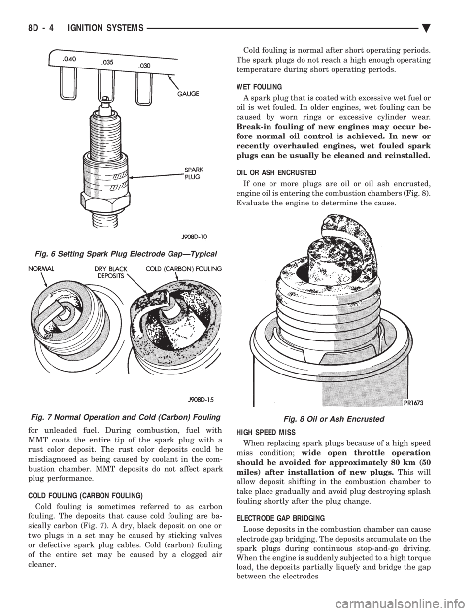
Adjust the gap between the electrodes (Fig. 6) to the
dimensions specified in the chart at the end of this
section. Always tighten spark plugs to the specified torque.
Over tightening can cause distortion and change
spark plug gap. Tighten spark plugs to 28 N Im (20 ft.
lbs.) torque.
SPARK PLUG CONDITION
NORMAL OPERATING CONDITIONS
The few deposits present will be probably light tan
or slightly gray in color with most grades of commer-
cial gasoline (Fig. 7). There will not be evidence of
electrode burning. Gap growth will not average more
than approximately 0.025 mm (.001 in) per 1600 km
(1000 miles) of operation. Spark plugs that have nor-
mal wear can usually be cleaned, have the electrodes
filed and regapped, and then reinstalled. Some fuel refiners in several areas of the United
States have introduced a manganese additive (MMT)
CABLE RESISTANCE CHART
Ä IGNITION SYSTEMS 8D - 3
Page 446 of 2438
for unleaded fuel. During combustion, fuel with
MMT coats the entire tip of the spark plug with a
rust color deposit. The rust color deposits could be
misdiagnosed as being caused by coolant in the com-
bustion chamber. MMT deposits do not affect spark
plug performance.
COLD FOULING (CARBON FOULING)
Cold fouling is sometimes referred to as carbon
fouling. The deposits that cause cold fouling are ba-
sically carbon (Fig. 7). A dry, black deposit on one or
two plugs in a set may be caused by sticking valves
or defective spark plug cables. Cold (carbon) fouling
of the entire set may be caused by a clogged air
cleaner. Cold fouling is normal after short operating periods.
The spark plugs do not reach a high enough operating
temperature during short operating periods.
WET FOULING
A spark plug that is coated with excessive wet fuel or
oil is wet fouled. In older engines, wet fouling can be
caused by worn rings or excessive cylinder wear.
Break-in fouling of new engines may occur be-
fore normal oil control is achieved. In new or
recently overhauled engines, wet fouled spark
plugs can be usually be cleaned and reinstalled.
OIL OR ASH ENCRUSTED
If one or more plugs are oil or oil ash encrusted,
engine oil is entering the combustion chambers (Fig. 8).
Evaluate the engine to determine the cause.
HIGH SPEED MISS When replacing spark plugs because of a high speed
miss condition; wide open throttle operation
should be avoided for approximately 80 km (50
miles) after installation of new plugs. This will
allow deposit shifting in the combustion chamber to
take place gradually and avoid plug destroying splash
fouling shortly after the plug change.
ELECTRODE GAP BRIDGING
Loose deposits in the combustion chamber can cause
electrode gap bridging. The deposits accumulate on the
spark plugs during continuous stop-and-go driving.
When the engine is suddenly subjected to a high torque
load, the deposits partially liquefy and bridge the gap
between the electrodes
Fig. 6 Setting Spark Plug Electrode GapÐTypical
Fig. 7 Normal Operation and Cold (Carbon) FoulingFig. 8 Oil or Ash Encrusted
8D - 4 IGNITION SYSTEMS Ä
Page 449 of 2438
pick-up (a Hall Effect device and magnet) through
which the shutter blades rotate. As the shutter
blades pass through the pick-up, they interrupt the
magnetic field. The Hall effect device in the pick-up
senses the change in the magnetic field and switches
on and off (which creates pulses), generating the in-
put signal to the PCM. The PCM calculates engine
speed through the number of pulses generated. On 2.5L MPI (flexible fuel AA-Body) engines, one
of the shutter blades has a window cut into it. The
PCM determines injector synchronization from the
window. Also, the PCM uses the input for detonation
control.
DISTRIBUTOR PICK-UPÐ3.0L ENGINE
The distributor pick-up provides two inputs to the
powertrain control module (PCM). From one input
the PCM determines RPM (engine speed). From the
other input it derives crankshaft position. The PCM
regulates injector synchronization and adjusts igni-
tion timing and engine speed based on these inputs. The distributor pick-up contains two signal gener-
ators. The pick-up unit consists of 2 light emitting
diodes (LED), 2 photo diodes, and a separate timing
disk. The timing disk contains two sets of slots. Each
set of slots rotates between a light emitting diode
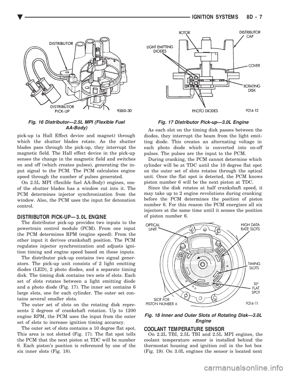
and a photo diode (Fig. 17). The inner set contains 6
large slots, one for each cylinder. The outer set con-
tains several smaller slots. The outer set of slots on the rotating disk repre-
sents 2 degrees of crankshaft rotation. Up to 1200
engine RPM, the PCM uses the input from the outer
set of slots to increase ignition timing accuracy. The outer set of slots contains a 10 degree flat spot.
This area is not slotted (Fig. 17). The flat spot tells
the PCM that the next piston at TDC will be number
6. Each piston's position is referenced by one of the
six inner slots (Fig. 18). As each slot on the timing disk passes between the
diodes, they interrupt the beam from the light emit-
ting diode. This creates an alternating voltage in
each photo diode which is converted into on-off
pulses. The pulses are the input to the PCM. During cranking, the PCM cannot determine which
cylinder will be at TDC until the 10 degree flat spot
on the outer set of slots rotates through the optical
unit. Once the flat spot is detected, the PCM knows
piston number 6 will be the next piston at TDC. Since the disk rotates at half crankshaft speed, it
may take up to 2 engine revolutions during cranking
before the PCM determines the position of piston
number 6. For this reason the PCM energizes all six
injectors at the same time until it senses the position
of piston number 6.
COOLANT TEMPERATURE SENSOR
On 2.2L TBI, 2.5L TBI and 2.5L MPI engines, the
coolant temperature sensor is installed behind the
thermostat housing and ignition coil in the hot box
(Fig. 19). On 3.0L engines the sensor is located next
Fig. 16 DistributorÐ2.5L MPI (Flexible Fuel AA-Body)Fig. 17 Distributor Pick-upÐ3.0L Engine
Fig. 18 Inner and Outer Slots of Rotating DiskÐ3.0L Engine
Ä IGNITION SYSTEMS 8D - 7
Page 450 of 2438
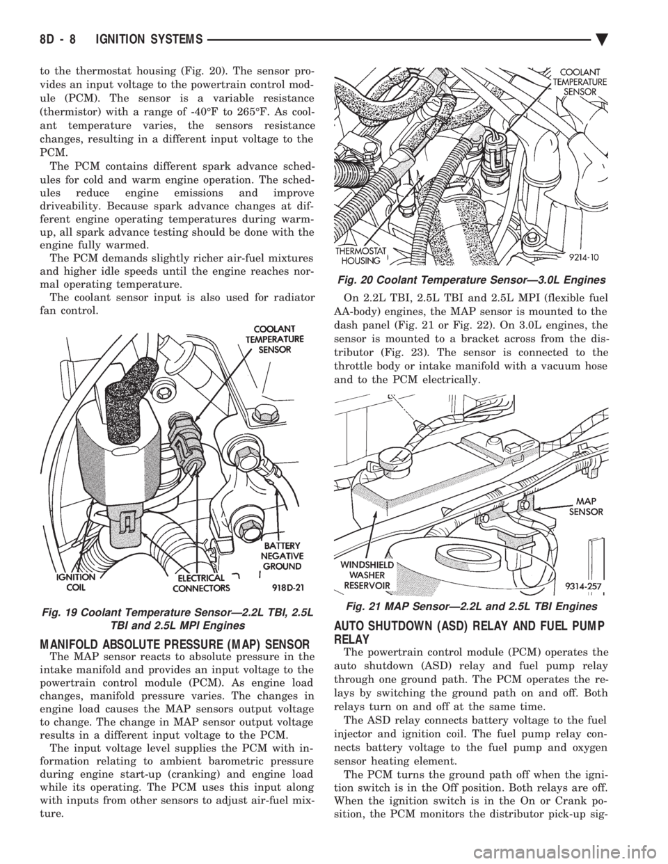
to the thermostat housing (Fig. 20). The sensor pro-
vides an input voltage to the powertrain control mod-
ule (PCM). The sensor is a variable resistance
(thermistor) with a range of -40ÉF to 265ÉF. As cool-
ant temperature varies, the sensors resistance
changes, resulting in a different input voltage to the
PCM. The PCM contains different spark advance sched-
ules for cold and warm engine operation. The sched-
ules reduce engine emissions and improve
driveability. Because spark advance changes at dif-
ferent engine operating temperatures during warm-
up, all spark advance testing should be done with the
engine fully warmed. The PCM demands slightly richer air-fuel mixtures
and higher idle speeds until the engine reaches nor-
mal operating temperature. The coolant sensor input is also used for radiator
fan control.
MANIFOLD ABSOLUTE PRESSURE (MAP) SENSOR
The MAP sensor reacts to absolute pressure in the
intake manifold and provides an input voltage to the
powertrain control module (PCM). As engine load
changes, manifold pressure varies. The changes in
engine load causes the MAP sensors output voltage
to change. The change in MAP sensor output voltage
results in a different input voltage to the PCM. The input voltage level supplies the PCM with in-
formation relating to ambient barometric pressure
during engine start-up (cranking) and engine load
while its operating. The PCM uses this input along
with inputs from other sensors to adjust air-fuel mix-
ture. On 2.2L TBI, 2.5L TBI and 2.5L MPI (flexible fuel
AA-body) engines, the MAP sensor is mounted to the
dash panel (Fig. 21 or Fig. 22). On 3.0L engines, the
sensor is mounted to a bracket across from the dis-
tributor (Fig. 23). The sensor is connected to the
throttle body or intake manifold with a vacuum hose
and to the PCM electrically.
AUTO SHUTDOWN (ASD) RELAY AND FUEL PUMP
RELAY
The powertrain control module (PCM) operates the
auto shutdown (ASD) relay and fuel pump relay
through one ground path. The PCM operates the re-
lays by switching the ground path on and off. Both
relays turn on and off at the same time. The ASD relay connects battery voltage to the fuel
injector and ignition coil. The fuel pump relay con-
nects battery voltage to the fuel pump and oxygen
sensor heating element. The PCM turns the ground path off when the igni-
tion switch is in the Off position. Both relays are off.
When the ignition switch is in the On or Crank po-
sition, the PCM monitors the distributor pick-up sig-
Fig. 19 Coolant Temperature SensorÐ2.2L TBI, 2.5L TBI and 2.5L MPI Engines
Fig. 20 Coolant Temperature SensorÐ3.0L Engines
Fig. 21 MAP SensorÐ2.2L and 2.5L TBI Engines
8D - 8 IGNITION SYSTEMS Ä
Page 468 of 2438
tance. The cables provide suppression of radio fre-
quency emissions from the ignition system.Check the spark plug cable connections for good
contact at the coil and distributor cap towers and at
the spark plugs. Terminals should be fully seated.
The nipples and spark plug covers should be in good
condition. Nipples should fit tightly on the coil and
distributor cap towers and spark plug cover should
fit tight around spark plug insulators. Loose cable
connections can cause ignition malfunctions by per-
mitting water to enter the towers, corroding, and in-
creasing resistance.
SPARK PLUGS
The 2.2L Turbo III, 3.3L and 3.8L engines use re-
sistor spark plugs. They have resistance values of
6,000 to 20,000 ohms when checked with at least a
1000 volt tester. Remove the spark plugs and examine them for
burned electrodes and fouled, cracked or broken por-
celain insulators. Keep plugs arranged in the order
in which they were removed from the engine. An iso-
lated plug displaying an abnormal condition indi-
cates that a problem exists in the corresponding
cylinder. Replace spark plugs at the intervals recom-
mended in Group O. Spark plugs that have low milage may be cleaned
and reused if not otherwise defective. Refer to the
Spark Plug Condition section of this group. After
cleaning, file the center electrode flat with a small
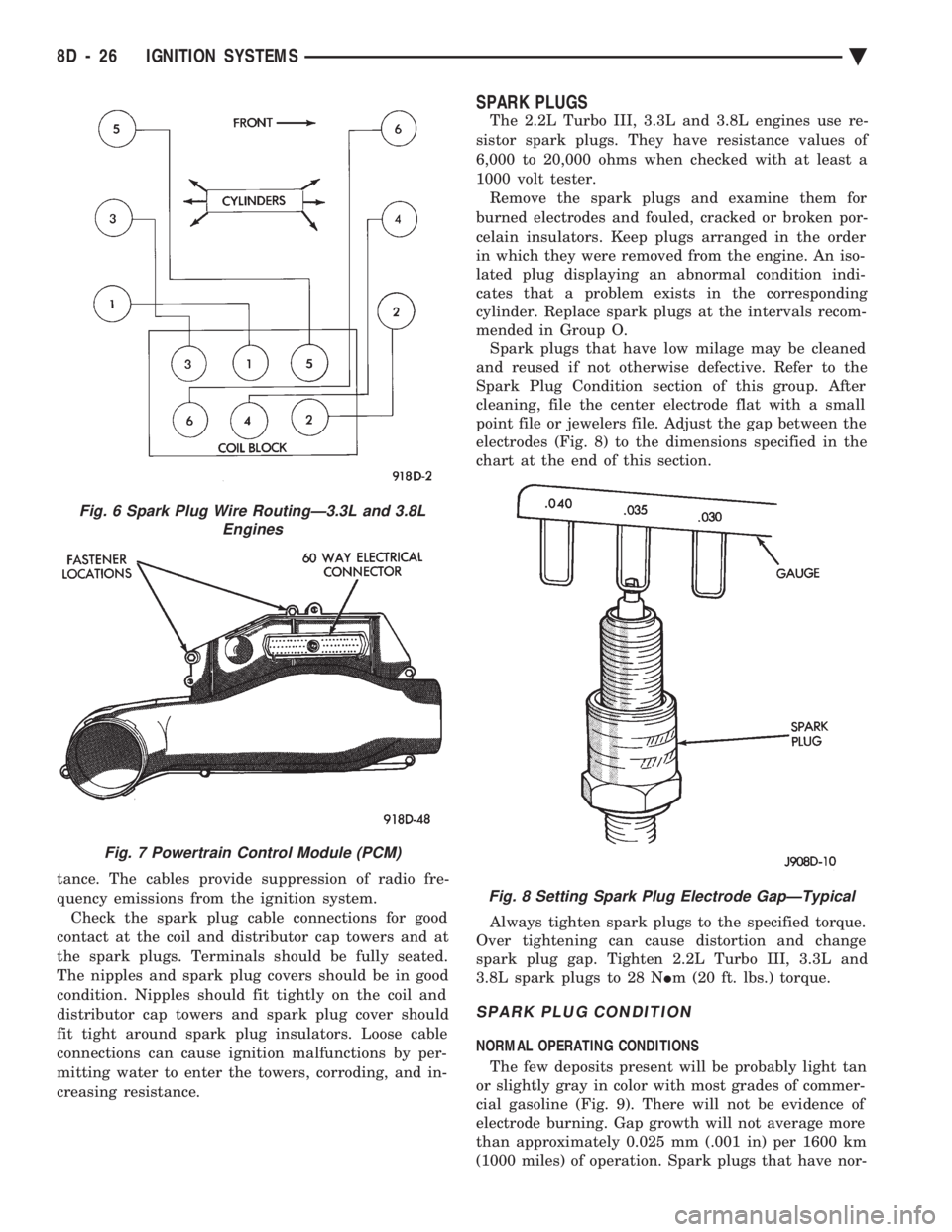
point file or jewelers file. Adjust the gap between the
electrodes (Fig. 8) to the dimensions specified in the
chart at the end of this section.
Always tighten spark plugs to the specified torque.
Over tightening can cause distortion and change
spark plug gap. Tighten 2.2L Turbo III, 3.3L and
3.8L spark plugs to 28 N Im (20 ft. lbs.) torque.
SPARK PLUG CONDITION
NORMAL OPERATING CONDITIONS
The few deposits present will be probably light tan
or slightly gray in color with most grades of commer-
cial gasoline (Fig. 9). There will not be evidence of
electrode burning. Gap growth will not average more
than approximately 0.025 mm (.001 in) per 1600 km
(1000 miles) of operation. Spark plugs that have nor-
Fig. 6 Spark Plug Wire RoutingÐ3.3L and 3.8L Engines
Fig. 7 Powertrain Control Module (PCM)
Fig. 8 Setting Spark Plug Electrode GapÐTypical
8D - 26 IGNITION SYSTEMS Ä
Page 469 of 2438
mal wear can usually be cleaned, have the electrodes
filed and regapped, and then reinstalled. Some fuel refiners in several areas of the United
States have introduced a manganese additive (MMT)
for unleaded fuel. During combustion, fuel with MMT
may coat the entire tip of the spark plug with a rust
colored deposit. The rust color deposits can be misdi-
agnosed as being caused by coolant in the combustion
chamber. Spark plug performance is not affected by
MMT deposits.
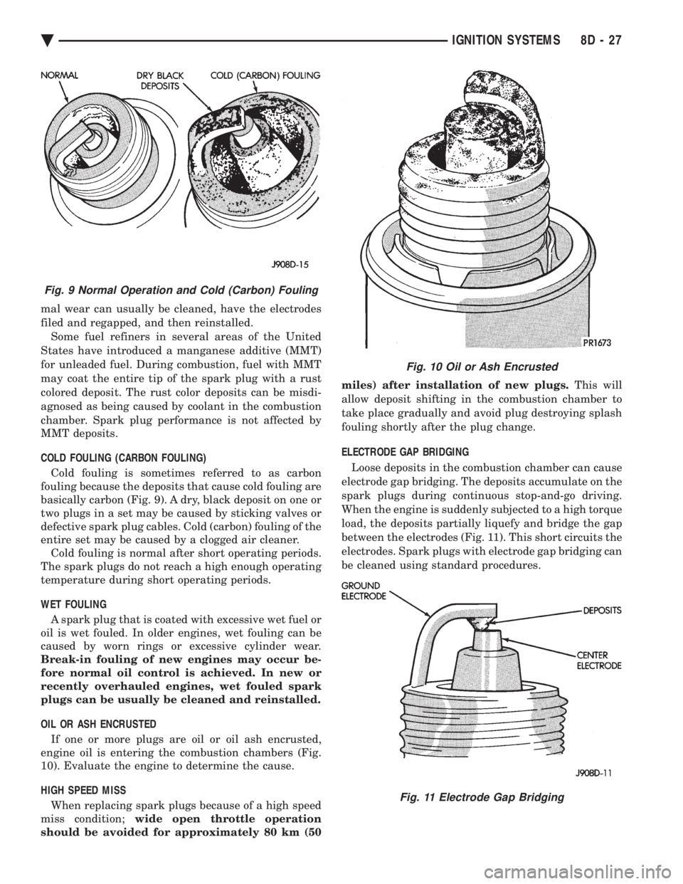
COLD FOULING (CARBON FOULING) Cold fouling is sometimes referred to as carbon
fouling because the deposits that cause cold fouling are
basically carbon (Fig. 9). A dry, black deposit on one or
two plugs in a set may be caused by sticking valves or
defective spark plug cables. Cold (carbon) fouling of the
entire set may be caused by a clogged air cleaner. Cold fouling is normal after short operating periods.
The spark plugs do not reach a high enough operating
temperature during short operating periods.
WET FOULING A spark plug that is coated with excessive wet fuel or
oil is wet fouled. In older engines, wet fouling can be
caused by worn rings or excessive cylinder wear.
Break-in fouling of new engines may occur be-
fore normal oil control is achieved. In new or
recently overhauled engines, wet fouled spark
plugs can be usually be cleaned and reinstalled.
OIL OR ASH ENCRUSTED If one or more plugs are oil or oil ash encrusted,
engine oil is entering the combustion chambers (Fig.
10). Evaluate the engine to determine the cause.
HIGH SPEED MISS When replacing spark plugs because of a high speed
miss condition; wide open throttle operation
should be avoided for approximately 80 km (50 miles) after installation of new plugs.
This will
allow deposit shifting in the combustion chamber to
take place gradually and avoid plug destroying splash
fouling shortly after the plug change.
ELECTRODE GAP BRIDGING
Loose deposits in the combustion chamber can cause
electrode gap bridging. The deposits accumulate on the
spark plugs during continuous stop-and-go driving.
When the engine is suddenly subjected to a high torque
load, the deposits partially liquefy and bridge the gap
between the electrodes (Fig. 11). This short circuits the
electrodes. Spark plugs with electrode gap bridging can
be cleaned using standard procedures.
Fig. 9 Normal Operation and Cold (Carbon) Fouling
Fig. 10 Oil or Ash Encrusted
Fig. 11 Electrode Gap Bridging
Ä IGNITION SYSTEMS 8D - 27
Page 474 of 2438
The coil's low primary resistance allows the PCM to
fully charge the coil for each firing.
COOLANT TEMPERATURE SENSOR
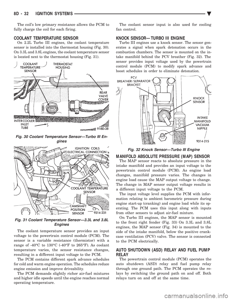
On 2.2L Turbo III engines, the coolant temperature
sensor is installed into the thermostat housing (Fig. 30).
On 3.3L and 3.8L engines, the coolant temperature sensor
is located next to the thermostat housing (Fig. 31).
The coolant temperature sensor provides an input
voltage to the powertrain control module (PCM). The
sensor is a variable resistance (thermistor) with a
range of -40ÉC to 130ÉC (-40ÉF to 265ÉF). As coolant
temperature varies, the sensor resistance changes,
resulting in a different input voltage to the PCM.
The PCM contains different spark advance schedules
for cold and warm engine operation. The schedules reduce
engine emission and improve driveability.
The PCM demands slightly richer air-fuel mixtures
and higher idle speeds until the engine reaches normal
operating temperature. The coolant sensor input is also used for cooling
fan control.
KNOCK SENSORÐTURBO III ENGINE
Turbo III engines use a knock sensor. The sensor gen-
erates a signal when spark detonation occurs in the
combustion chambers. The sensor is mounted on the in-
take manifold behind the PCV breather (Fig. 32). The
sensor provides input voltage used by the powertrain
control module (PCM) to modify spark advance and
boost schedules in order to eliminate detonation.
MANIFOLD ABSOLUTE PRESSURE (MAP) SENSOR
The MAP sensor reacts to absolute pressure in the
intake manifold and provides an input voltage to the
powertrain control module (PCM). As engine load
changes, manifold pressure varies. The changes in
engine load cause the MAP output voltage to change.
The change in MAP sensor output voltage results in
a different input voltage to the PCM.
The input voltage level supplies the PCM with infor-
mation relating to ambient barometric pressure during
engine start-up (cranking) and engine load while its op-
erating. The PCM uses this input along with inputs
from other sensors to adjust air-fuel mixture.
On Turbo III engines, the MAP sensor is mounted
to the front right fender (Fig. 33) On 3.3L and 3.8L
engines, the MAP sensor (Fig. 34) is mounted to the
side of the intake manifold, below the positive crank-
case ventilation (PCV) valve. The sensor is connected
to the PCM electrically.
AUTO SHUTDOWN (ASD) RELAY AND FUEL PUMP
RELAY
The powertrain control module (PCM) operates the
auto shutdown (ASD) relay and fuel pump relay
through one ground path. The PCM operates the re-
lays by switching the ground path on and off. Both
relays turn on and off at the same time.
Fig. 32 Knock SensorÐTurbo III Engine
Fig. 30 Coolant Temperature SensorÐTurbo III En- gines
Fig. 31 Coolant Temperature SensorÐ3.3L and 3.8LEngines
8D - 32 IGNITION SYSTEMS Ä