oil change CHEVROLET DYNASTY 1993 Workshop Manual
[x] Cancel search | Manufacturer: CHEVROLET, Model Year: 1993, Model line: DYNASTY, Model: CHEVROLET DYNASTY 1993Pages: 2438, PDF Size: 74.98 MB
Page 1832 of 2438
noid is energized. The solenoid mounts to the passen-
ger side inner fender panel, next to the strut tower
(Fig. 17).
MODES OF OPERATION
As input signals to the PCM change, the PCM
adjusts its response to the output devices. For example,
the PCM must calculate a different injector pulse
width and ignition timing for idle than it does for wide
open throttle (WOT). There are several different modes
of operation that determine how the PCM responds to
the various input signals. There are two different areas of operation, OPEN
LOOP and CLOSED LOOP. During OPEN LOOP modes, the PCM receives input
signals and responds according to preset PCM pro-
gramming. Input from the oxygen (O
2) sensor is not
monitored during OPEN LOOP modes. During CLOSED LOOP modes, the PCM does moni-
tor the oxygen (O
2) sensor input. This input indicates
to the PCM whether or not the calculated injector pulse
width results in the ideal air-fuel ratio of 14.7 parts air
to 1 part fuel. By monitoring the exhaust oxygen
content through the O
2sensor, the PCM can fine tune
the injector pulse width to achieve optimum fuel
economy combined with low emissions. The 2.2L Turbo III multi-port fuel injection system
has the following modes of operation:
² Ignition switch ON - Zero RPM
² Engine start-up
² Engine warm-up
² Cruise (Idle)
² Acceleration
² Deceleration
² Wide Open Throttle
² Ignition switch OFF
The engine start-up (crank), engine warm-up, and
wide open throttle modes are OPEN LOOP modes. The
acceleration, deceleration, and cruise modes, with the
engine at operating temperature are CLOSED
LOOP modes (under most operating conditions).
IGNITION SWITCH ON (ZERO RPM) MODE
When the ignition switch activates the fuel injection
system the following actions occur:
²
The PCM calculates basic fuel strategy by determining
atmospheric air pressure from the MAP sensor input.
² The PCM monitors the coolant temperature sensor
and throttle position sensor input. The PCM modifies
fuel strategy based on this input. When the key is in the ON position and the engine is
not running, the auto shutdown (ASD) relay and fuel
pump relay are not energized. Therefore battery volt-
age is not supplied to the fuel pump, ignition coil, fuel
injector or oxygen sensor heating element.
ENGINE START-UP MODE
This is an OPEN LOOP mode. The following actions
occur when the starter motor is engaged. If the PCM receives the camshaft position and crank-
shaft position sensor signals, it energizes the auto
shutdown (ASD) relay and fuel pump relay. These
relays supply battery voltage to the fuel pump, fuel
injectors, ignition coil, and oxygen sensor heating ele-
ment. If the PCM does not receive the camshaft posi-
tion sensor and crankshaft position sensor signals
within approximately one second, it de-energizes the
ASD relay and fuel pump relay. The PCM energizes all injectors until it determines
crankshaft position from the camshaft position sensor
and crankshaft position sensor signals. The PCM de-
termines crankshaft position within 1 engine revolu-
tion. After determining crankshaft position, the PCM be-
gins energizing the injectors in sequence. The PCM
adjusts injector pulse width and controls injector syn-
chronization by turning the individual ground paths to
the injectors On and Off. When the engine idles within 664 RPM of its target
RPM, the PCM compares current MAP sensor value
with the atmospheric pressure value received during
the Ignition Switch On (zero RPM) mode. If the PCM
does not detect a minimum difference between the two
values, it sets a MAP fault into memory. Once the ASD and fuel pump relays have been
energized, the PCM:
² Determines injector pulse width based on coolant
temperature, manifold absolute pressure (MAP) and
the number of engine revolutions since cranking was
initiated.
² Monitors the coolant temperature sensor, camshaft
position sensor, crankshaft position sensor, MAP sen-
sor, and throttle position sensor to determine correct
ignition timing.
ENGINE WARM-UP MODE
This is a OPEN LOOP mode. The following inputs
are received by the PCM:
² engine coolant temperature
² knock sensor
² manifold absolute pressure (MAP)
² engine speed (crankshaft position sensor)
² throttle position
² A/C switch
² battery voltage
The PCM provides a ground path for the injectors to
precisely control injector pulse width (by switching the
ground on and off). The PCM adjusts engine idle speed
through the idle air control motor. Also, the PCM
regulates ignition timing.
14 - 92 FUEL SYSTEMS Ä
Page 1845 of 2438
Wastegate Duty Cycle
Battery Temperature
Map Sensor Voltage
Vehicle Speed
Oxygen Sensor State
Baro Read Update
MAP Gauge Reading
Throttle Opening (percentage)
Total Spark Advance
CIRCUIT ACTUATION TEST MODE
The purpose of the circuit actuation test mode is to
check for the proper operation of output circuits or
devices which the powertrain control module (PCM)
cannot internally recognize. The PCM can attempt to
activate these outputs and allow an observer to ver-
ify proper operation. Most of the tests available in
this mode provide an audible or visual indication of
device operation (click of relay contacts, spray fuel,
etc.). With the exception of an intermittent condition,
if a device functions properly during its test, assume
the device, its associated wiring, and its driver cir-
cuit are in working order.
OBTAINING CIRCUIT ACTUATION TEST
Connect the DRBII scan tool to the vehicle and ac-
cess the Actuators screen. The following is a list of
the engine control system functions accessible
through Actuators screens. Stop All Tests
Ignition Coil #1
Ignition Coil #2
Fuel Injector #1
Fuel Injector #2
Fuel Injector #3
Idle Air Control Motor Open/Close
Radiator Fan Relay
A/C Clutch Relay
Auto Shutdown Relay
Purge Solenoid
S/C Serv Solenoids
Generator Field
Tachometer Output
Wastegate Solenoid
Baro Read Solenoid
All Solenoids/Relays
Speed Control Vent Solenoid
Speed Control Vacuum Solenoid
ASD Fuel System Test
Fuel Injector #4
THROTTLE BODY MINIMUM AIR FLOW CHECK
PROCEDURE
(1) Warm the engine in neutral until the cooling
fan has cycled on and off at least once. (2) Shut off engine.
(3) Hook-up Tachometer.
(4) Disconnect the PCV valve hose from the nipple
on the intake manifold. (5) Attach air metering fitting, special tool 6457
(0.125 inch orifice), to the intake manifold PCV nip-
ple. (6) Disconnect 3/16 inch manifold vacuum purge
line from the top of the throttle body. Cap the 3/16
inch throttle body nipple. (7) Connect DRBII scan tool.
(8) Restart engine. Allow engine to idle for at least
one minute. (9) Using the DRBII scan tool, access Min. Airflow
Idle Spd. The following will then occur:
² Idle air control motor will fully close.
² Idle spark advance will become fixed.
² Engine RPM will be displayed on the DRBII scan
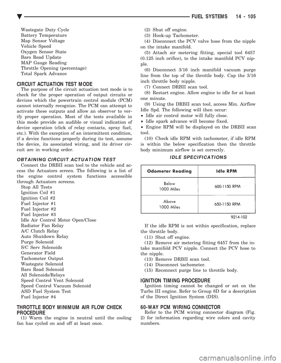
tool. (10) Check idle RPM with tachometer, if idle RPM
is within the below specification then the throttle
body minimum airflow is set correctly.
If the idle RPM is not within specification, replace
the throttle body. (11) Shut off engine.
(12) Remove air metering fitting 6457 from the in-
take manifold PCV nipple. Connect the PCV hose to
the nipple. (13) Remove DRBII scan tool.
(14) Disconnect tachometer.
(15) Reconnect purge line to throttle body.
IGNITION TIMING PROCEDURE
Ignition timing cannot be changed or set on the
Turbo III engine. Refer to Group 8D for a description
of the Direct Ignition System (DIS).
60-WAY PCM WIRING CONNECTOR
Refer to the PCM wiring connector diagram (Fig.
2) for information regarding wire colors and cavity
numbers.
IDLE SPECIFICATIONS
Ä FUEL SYSTEMS 14 - 105
Page 1853 of 2438
3.0L MULTI-PORT FUEL INJECTIONÐSYSTEM OPERATION INDEX
page page
Air Conditioning (A/C) Clutch Relay (AA, AG, AJ Body)ÐPCM Output .................... 118
Air Conditioning (A/C) Clutch Relay (AC Body) ÐPCM Output ........................ 118
Air Conditioning Switch Sense (AA, AG, AJ Body)ÐPCM Input ..................... 115
Air Conditioning Switch Sense (AC Body)ÐPCM Input ................................ 115
Auto Shutdown (ASD) Relay and Fuel Pump RelayÐPCM Output .................... 119
Battery VoltageÐPCM Input ............... 115
Brake SwitchÐPCM Input ................. 115
CCD Bus .............................. 113
Data Link ConnectorÐPCM Output .......... 120
Distributor Pick-UpÐPCM Input ............. 115
Duty Cycle Evap Canister Purge Solenoid ÐPCM Output ........................ 119
Engine Coolant Temperature Sensor ÐPCM Input ......................... 115
Fuel InjectorsÐPCM Output ............... 120
Fuel Pressure Regulator .................. 124
Fuel Supply Circuit ...................... 123
General Information ...................... 113 Generator FieldÐPCM Output
.............. 118
Heated Oxygen Sensor (O
2Sensor)
ÐPCM Input ......................... 116
Idle Air Control MotorÐPCM Output ......... 119
Ignition CoilÐPCM Output ................. 121
Malfunction Indicator Lamp (Check Engine Lamp)ÐPCM Output ................... 120
Manifold Absolute Pressure (MAP) Sensor ÐPCM Input ......................... 116
Modes of Operation ...................... 121
Park/Neutral SwitchÐPCM Input ............ 117
Part Throttle Unlock SolenoidÐPCM Output . . . 121
Powertrain Control Module ................. 113
Radiator Fan RelayÐPCM Output ........... 121
Speed Control SolenoidsÐPCM Output ....... 121
Speed ControlÐPCM Input ................ 117
System Diagnosis ....................... 113
TachometerÐPCM Output ................. 121
Throttle Body ........................... 123
Throttle Position Sensor (TPS)ÐPCM Input .... 117
Transaxle Control ModuleÐPCM Output ...... 120
Vehicle Speed and Distance InputÐPCM Input . 118
Vehicle Speed SensorÐPCM Input .......... 118
GENERAL INFORMATION
The 3.0L engine uses a sequential Multi-Port Elec-
tronic Fuel Injection system (Fig. 1). The MPI system
is computer regulated and provides precise air/fuel
ratios for all driving conditions. The MPI system is operated by the powertrain con-
trol module (PCM). The PCM regulates ignition timing, air-fuel ratio,
emission control devices, cooling fan, charging sys-
tem, idle speed and speed control. Various sensors
provide the inputs necessary for the PCM to correctly
operate these systems. In addition to the sensors,
various switches also provide inputs to the PCM. All inputs to the PCM are converted into signals.
The PCM can adapt its programming to meet chang-
ing operating conditions. Fuel is injected into the intake port above the in-
take valve in precise metered amounts through elec-
trically operated injectors. The PCM fires the
injectors in a specific sequence. The PCM maintains
an air fuel ratio of 14.7 parts air to 1 part fuel by
constantly adjusting injector pulse width. Injector
pulse width is the length of time the injector is ener-
gized. The PCM adjusts injector pulse width by opening
and closing the ground path to the injector. Engine
RPM (speed) and manifold absolute pressure (air
density) are the primary inputs that determine injec-
tor pulse width.
SYSTEM DIAGNOSIS
The powertrain control module (PCM) tests many
of its own input and output circuits. If a fault is
found in a major system, the information is stored in
memory. Technicians can display fault information
through the malfunction indicator lamp (instrument
panel Check Engine lamp) or by connecting the
DRBII scan tool. For diagnostic trouble code informa-
tion, refer to the 3.0 Multi-Port Fuel InjectionÐOn-
Board Diagnostics section of this group.
CCD BUS
Various modules exchange information through a
communications port called the CCD Bus. The pow-
ertrain control module (PCM) transmits the malfunc-
tion indicator (instrument panel check engine lamp)
On/Off signal, engine RPM and vehicle load data on
the CCD Bus.
POWERTRAIN CONTROL MODULE
The powertrain control module (PCM) is a digital
computer containing a microprocessor (Fig. 2). The
PCM receives input signals from various switches
and sensors that are referred to as PCM Inputs.
Based on these inputs, the PCM adjusts various en-
gine and vehicle operations through devices referred
to as PCM Outputs. PCM Inputs:
² Air Conditioning Controls
² Battery Voltage
² Brake Switch
Ä FUEL SYSTEMS 14 - 113
Page 1854 of 2438
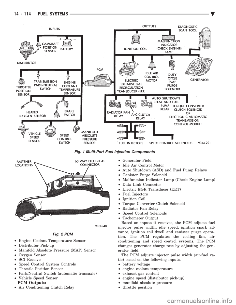
² Engine Coolant Temperature Sensor
² Distributor Pick-up
² Manifold Absolute Pressure (MAP) Sensor
² Oxygen Sensor
² SCI Receive
² Speed Control System Controls
² Throttle Position Sensor
² Park/Neutral Switch (automatic transaxle)
² Vehicle Speed Sensor
PCM Outputs:
² Air Conditioning Clutch Relay ²
Generator Field
² Idle Air Control Motor
² Auto Shutdown (ASD) and Fuel Pump Relays
² Canister Purge Solenoid
² Malfunction Indicator Lamp (Check Engine Lamp)
² Data Link Connector
² Electric EGR Transducer (EET)
² Fuel Injectors
² Ignition Coil
² Torque Converter Clutch Solenoid
² Radiator Fan Relay
² Speed Control Solenoids
² Tachometer Output
Based on inputs it receives, the PCM adjusts fuel
injector pulse width, idle speed, ignition spark ad-
vance, ignition coil dwell and canister purge opera-
tion. The PCM regulates the cooling fan, air
conditioning and speed control systems. The PCM
changes generator charge rate by adjusting the gen-
erator field. The PCM adjusts injector pulse width (air-fuel ra-
tio) based on the following inputs.
² battery voltage
² engine coolant temperature
² exhaust gas content
² engine speed (distributor pick-up)
² manifold absolute pressure
² throttle position
Fig. 1 Multi-Port Fuel Injection Components
Fig. 2 PCM
14 - 114 FUEL SYSTEMS Ä
Page 1855 of 2438
The PCM adjusts ignition timing based on the fol-
lowing inputs.
² engine coolant temperature
² engine speed (distributor pick-up)
² manifold absolute pressure
² throttle position
The Automatic Shut Down (ASD) and Fuel Pump
relays are mounted externally, but turned on and off
by the PCM through the same circuit. The distributor pick-up signal is sent to the PCM.
If the PCM does not receive a distributor signal
within approximately one second of engine cranking,
the ASD relay and fuel pump relay are deactivated.
When these relays are deactivated, power is shut off
to the fuel injector, ignition coil, oxygen sensor heat-
ing element and fuel pump. The PCM contains a voltage converter that
changes battery voltage to a regulated 8.0 volts. The
8.0 volts power the distributor pick-up and vehicle
speed sensor. The PCM also provides a 5.0 volts sup-
ply for the coolant temperature sensor, manifold ab-
solute pressure sensor and throttle position sensor.
AIR CONDITIONING SWITCH SENSE (AA, AG, AJ
BODY)ÐPCM INPUT
When the air conditioning or defrost switch is in
the ON position and the low pressure and high pres-
sure switches are closed, the PCM receives an input
for air conditioning. After receiving this input, the
PCM activates the A/C compressor clutch by ground-
ing the A/C clutch relay. The PCM also adjusts idle
speed to a scheduled RPM to compensate for in-
creased engine load.
AIR CONDITIONING SWITCH SENSE (AC
BODY)ÐPCM INPUT
When the air conditioning or defrost switch is in
the ON position and the low pressure, high pressure
and ambient temperature switches are closed, the
PCM receives an input for air conditioning. After re-
ceiving this input, the PCM activates the A/C com-
pressor clutch by grounding the A/C clutch relay.
The PCM also adjusts idle speed to a scheduled RPM
to compensate for increased engine load.
BATTERY VOLTAGEÐPCM INPUT
The PCM monitors the battery voltage input to de-
termine fuel injector pulse width and generator field
control. If battery voltage is low, the PCM will in-
crease injector pulse width.
BRAKE SWITCHÐPCM INPUT
When the brake switch is activated, the PCM re-
ceives an input indicating that the brakes are being
applied. After receiving this input the PCM main-
tains idle speed to a scheduled RPM through the idle
air control motor. The brake switch is mounted on
the brake pedal support bracket.
ENGINE COOLANT TEMPERATURE SENSORÐPCM
INPUT
The coolant temperature sensor is a variable resis-
tor with a range of -40É to 265É. The sensor is in-
stalled next to the thermostat housing. The PCM supplies 5.0 volts to the coolant temper-
ature sensor. The sensor provides an input voltage to
the PCM (Fig. 3). As coolant temperature varies, the
sensors resistance changes, resulting in a different
input voltage to the PCM. The PCM demands slightly richer air-fuel mixtures
and higher idle speeds until the engine reaches nor-
mal operating temperature. This sensor is also used for cooling fan control.
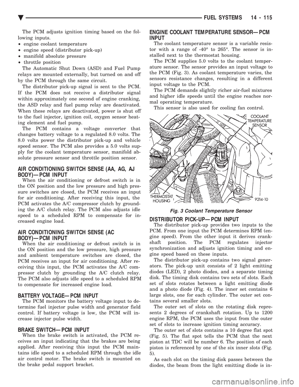
DISTRIBUTOR PICK-UPÐPCM INPUT
The distributor pick-up provides two inputs to the
PCM. From one input the PCM determines RPM (en-
gine speed). From the other input it derives crank-
shaft position. The PCM regulates injector
synchronization and adjusts ignition timing and en-
gine speed based on these inputs. The distributor pick-up contains two signal gener-
ators. The pick-up unit consists of 2 light emitting
diodes (LED), 2 photo diodes, and a separate timing
disk. The timing disk contains two sets of slots. Each
set of slots rotates between a light emitting diode
and a photo diode (Fig. 4). The inner set contains 6
large slots, one for each cylinder. The outer set con-
tains several smaller slots. The outer set of slots on the rotating disk repre-
sents 2 degrees of crankshaft rotation. Up to 1200
engine RPM, the PCM uses the input from the outer
set of slots to increase ignition timing accuracy. The outer set of slots contains a 10 degree flat spot
(Fig. 5). The flat spot tells the PCM that the next
piston at TDC will be number 6. The position of each
piston is referenced by one of the six inner slots (Fig.
5). As each slot on the timing disk passes between the
diodes, the beam from the light emitting diode is in-
Fig. 3 Coolant Temperature Sensor
Ä FUEL SYSTEMS 14 - 115
Page 1861 of 2438
tially energizes all injectors at the same time. Once
the PCM determines crankshaft position, it begins
energizing the injectors in sequence.Battery voltage is supplied to the injectors through
the ASD relay. The PCM provides the ground path
for the injectors. By switching the ground path on
and off, the PCM adjusts injector pulse width. Pulse
width is the amount of time the injector is energized.
The PCM adjusts injector pulse width based on in-
puts it receives.
IGNITION COILÐPCM OUTPUT
The auto shutdown (ASD) relay provides battery
voltage to the ignition coil. The PCM provides a
ground contact (circuit) for energizing coil. When the
PCM breaks the contact, the energy in the coil pri-
mary transfers to the secondary causing the spark.
The PCM will de-energize the ASD relay if it does
not receive an input from the distributor pick-up. Re-
fer to Auto Shutdown (ASD) Relay/Fuel Pump Re-
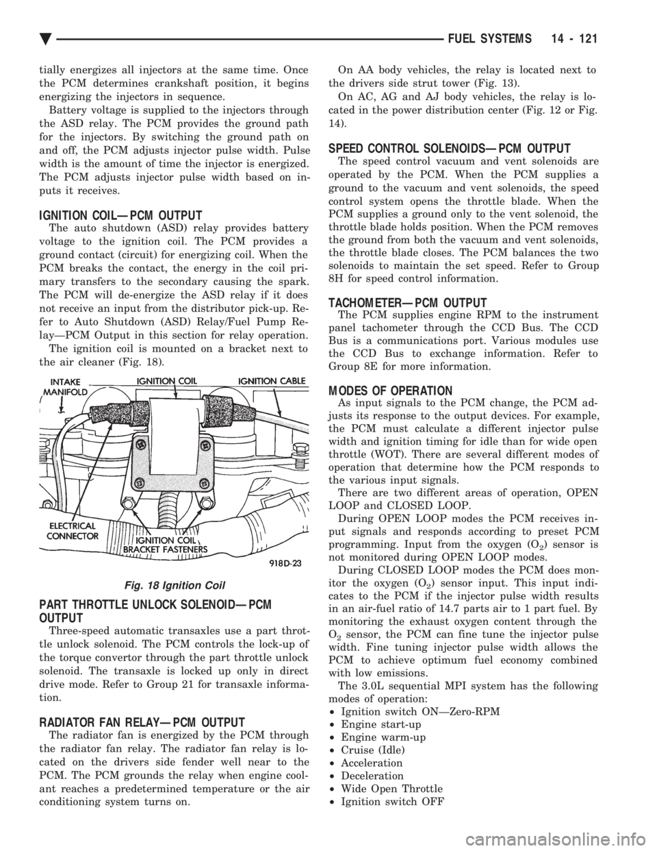
layÐPCM Output in this section for relay operation. The ignition coil is mounted on a bracket next to
the air cleaner (Fig. 18).
PART THROTTLE UNLOCK SOLENOIDÐPCM
OUTPUT
Three-speed automatic transaxles use a part throt-
tle unlock solenoid. The PCM controls the lock-up of
the torque convertor through the part throttle unlock
solenoid. The transaxle is locked up only in direct
drive mode. Refer to Group 21 for transaxle informa-
tion.
RADIATOR FAN RELAYÐPCM OUTPUT
The radiator fan is energized by the PCM through
the radiator fan relay. The radiator fan relay is lo-
cated on the drivers side fender well near to the
PCM. The PCM grounds the relay when engine cool-
ant reaches a predetermined temperature or the air
conditioning system turns on. On AA body vehicles, the relay is located next to
the drivers side strut tower (Fig. 13). On AC, AG and AJ body vehicles, the relay is lo-
cated in the power distribution center (Fig. 12 or Fig.
14).
SPEED CONTROL SOLENOIDSÐPCM OUTPUT
The speed control vacuum and vent solenoids are
operated by the PCM. When the PCM supplies a
ground to the vacuum and vent solenoids, the speed
control system opens the throttle blade. When the
PCM supplies a ground only to the vent solenoid, the
throttle blade holds position. When the PCM removes
the ground from both the vacuum and vent solenoids,
the throttle blade closes. The PCM balances the two
solenoids to maintain the set speed. Refer to Group
8H for speed control information.
TACHOMETERÐPCM OUTPUT
The PCM supplies engine RPM to the instrument
panel tachometer through the CCD Bus. The CCD
Bus is a communications port. Various modules use
the CCD Bus to exchange information. Refer to
Group 8E for more information.
MODES OF OPERATION
As input signals to the PCM change, the PCM ad-
justs its response to the output devices. For example,
the PCM must calculate a different injector pulse
width and ignition timing for idle than for wide open
throttle (WOT). There are several different modes of
operation that determine how the PCM responds to
the various input signals. There are two different areas of operation, OPEN
LOOP and CLOSED LOOP. During OPEN LOOP modes the PCM receives in-
put signals and responds according to preset PCM
programming. Input from the oxygen (O
2) sensor is
not monitored during OPEN LOOP modes. During CLOSED LOOP modes the PCM does mon-
itor the oxygen (O
2) sensor input. This input indi-
cates to the PCM if the injector pulse width results
in an air-fuel ratio of 14.7 parts air to 1 part fuel. By
monitoring the exhaust oxygen content through the
O
2sensor, the PCM can fine tune the injector pulse
width. Fine tuning injector pulse width allows the
PCM to achieve optimum fuel economy combined
with low emissions. The 3.0L sequential MPI system has the following
modes of operation:
² Ignition switch ONÐZero-RPM
² Engine start-up
² Engine warm-up
² Cruise (Idle)
² Acceleration
² Deceleration
² Wide Open Throttle
² Ignition switch OFF
Fig. 18 Ignition Coil
Ä FUEL SYSTEMS 14 - 121
Page 1874 of 2438
SYSTEM TESTS
WARNING: APPLY PARKING BRAKE AND/OR BLOCK
WHEELS BEFORE PERFORMING ANY TEST ON AN
OPERATING ENGINE.
OBTAINING DIAGNOSTIC TROUBLE CODES
(1) Connect DRBII scan tool to the data link connec-
tor located in the engine compartment near the pow-
ertrain control module (PCM). (2) Start the engine if possible, cycle the transaxle
selector and the A/Cswitch if applicable. Shut off the
engine. (3) Turn the ignition switch on, access Read Fault
Screen. Record all the fault messages shown on the
DRBII scan tool. Observe the malfunction indicator
lamp (Check Engine lamp on the instrument panel).
The lamp should light for 3 seconds then go out (bulb
check). Diagnostic trouble code erasure; access erase
diagnostic trouble code data
STATE DISPLAY TEST MODE
The switch inputs used by the powertrain control
module (PCM) have only two recognized states, HIGH
and LOW. For this reason, the PCM cannot recognize
the difference between a selected switch position ver-
sus an open circuit, a short circuit, or a defective
switch. If the change is displayed, it can be assumed
that the entire switch circuit to the PCM is functional.
From the state display screen access either State
Display Inputs and Outputs or State Display Sensors.
STATE DISPLAY INPUTS AND OUTPUTS
Connect the DRBII scan tool to the vehicle. Access
the State Display screen. Then access Inputs and
Outputs. The following is a list of the engine control
system functions accessible through the Inputs and
Outputs screen. Park/Neutral Switch
Speed Control Resume
Brake Switch
Speed Control On/Off
Speed Control Set
A/C Switch Sense
S/C Vent Solenoid
S/C Vacuum Solenoid
A/C Clutch Relay
EGR Solenoid
Auto Shutdown Relay
Radiator Fan Relay
Purge Solenoid
Torque Converter Clutch Solenoid
Malfunction Indicator Lamp (Check Engine Lamp)
STATE DISPLAY SENSORS
Connect the DRBII scan tool to the vehicle and ac-
cess the State Display screen. Then access Sensor
Display. The following is a list of the engine control
system functions accessible through the Sensor Dis-
play screen. Battery Temperature
Oxygen Sensor Signal
Engine Coolant Temperature
Engine Coolant Temp Sensor
Throttle Position
Minimum Throttle
Battery Voltage
MAP Sensor Reading
Idle Air Control Motor Position
Adaptive Fuel Factor
Barometric Pressure
Min Airflow Idle Speed
Engine Speed
Fault #1 Key-On Info
Module Spark Advance
Speed Control Target
Fault #2 Key-on Info
Fault #3 Key-on Info
Speed Control Status
Speed Control Switch Voltage
Charging System Goal
Theft Alarm Status
Map Sensor Voltage
Vehicle Speed
Oxygen Sensor State
MAP Gauge Reading
Throttle Opening (percentage)
Total Spark Advance
CIRCUIT ACTUATION TEST MODE
The circuit actuation test mode checks for proper
operation of output circuits or devices which the pow-
ertrain control module (PCM) cannot internally rec-
ognize. The PCM can attempt to activate these
outputs and allow an observer to verify proper oper-
ation. Most of the tests provide an audible or visual
indication of device operation (click of relay contacts,
spray fuel, etc.). Except for intermittent conditions, if
a device functions properly during testing, assume
the device, its associated wiring, and driver circuit
working correctly.
OBTAINING CIRCUIT ACTUATION TEST
Connect the DRBII scan tool to the vehicle and ac-
cess the Actuators screen. The following is a list of
the engine control system functions accessible
through Actuators screens. Stop All Tests
Ignition Coil #1
Fuel Injector #1
Fuel Injector #2
Fuel Injector #3
14 - 134 FUEL SYSTEMS Ä
Page 1886 of 2438
The PCM regulates ignition timing, air-fuel ratio,
emission control devices, cooling fan, charging sys-
tem, idle speed and speed control. Various sensors
provide the inputs necessary for the PCM to correctly
operate these systems. In addition to the sensors,
various switches also provide inputs to the PCM. All inputs to the PCM are converted into signals.
The PCM can adapt its programming to meet chang-
ing operating conditions. Fuel is injected into the intake port above the in-
take valve in precise metered amounts through elec-
trically operated injectors. The PCM fires the
injectors in a specific sequence. The PCM maintains
an air fuel ratio of 14.7 parts air to 1 part fuel by
constantly adjusting injector pulse width. Injector
pulse width is the length of time the injector is ener-
gized. The PCM adjusts injector pulse width by opening
and closing the ground path to the injector. Engine
RPM (speed) and manifold absolute pressure (air
density) are the primary inputs that determine injec-
tor pulse width.
SYSTEM DIAGNOSIS
The PCM tests many of its own input and output
circuits. If a fault is found in a major system, the in-
formation is stored in memory. Technicians can dis-
play fault information through the malfunction
indicator lamp (instrument panel Check Engine
lamp) or by connecting the DRBII scan tool. For di-
agnostic trouble code information, refer to the 3.3L/
3.8L Multi-Point Fuel InjectionÐOn-Board
Diagnostics section of this group.
CCD BUS
Various modules exchange information through a
communications port called the CCD Bus. The pow-
ertrain control module (PCM) transmits engine RPM
and vehicle load information on the CCD Bus.
POWERTRAIN CONTROL MODULE
The powertrain control module (PCM) is a digital
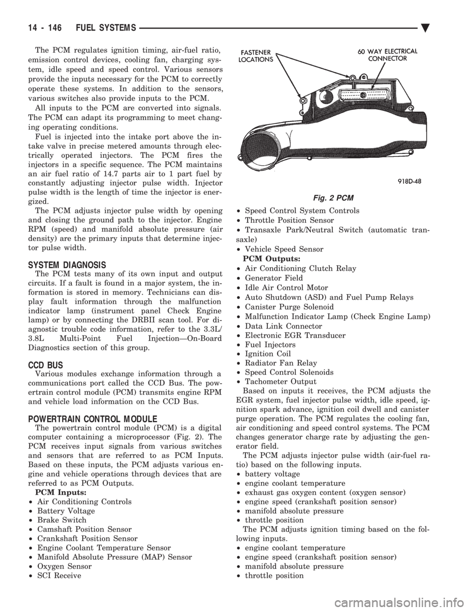
computer containing a microprocessor (Fig. 2). The
PCM receives input signals from various switches
and sensors that are referred to as PCM Inputs.
Based on these inputs, the PCM adjusts various en-
gine and vehicle operations through devices that are
referred to as PCM Outputs. PCM Inputs:
² Air Conditioning Controls
² Battery Voltage
² Brake Switch
² Camshaft Position Sensor
² Crankshaft Position Sensor
² Engine Coolant Temperature Sensor
² Manifold Absolute Pressure (MAP) Sensor
² Oxygen Sensor
² SCI Receive ²
Speed Control System Controls
² Throttle Position Sensor
² Transaxle Park/Neutral Switch (automatic tran-
saxle)
² Vehicle Speed Sensor
PCM Outputs:
² Air Conditioning Clutch Relay
² Generator Field
² Idle Air Control Motor
² Auto Shutdown (ASD) and Fuel Pump Relays
² Canister Purge Solenoid
² Malfunction Indicator Lamp (Check Engine Lamp)
² Data Link Connector
² Electronic EGR Transducer
² Fuel Injectors
² Ignition Coil
² Radiator Fan Relay
² Speed Control Solenoids
² Tachometer Output
Based on inputs it receives, the PCM adjusts the
EGR system, fuel injector pulse width, idle speed, ig-
nition spark advance, ignition coil dwell and canister
purge operation. The PCM regulates the cooling fan,
air conditioning and speed control systems. The PCM
changes generator charge rate by adjusting the gen-
erator field. The PCM adjusts injector pulse width (air-fuel ra-
tio) based on the following inputs.
² battery voltage
² engine coolant temperature
² exhaust gas oxygen content (oxygen sensor)
² engine speed (crankshaft position sensor)
² manifold absolute pressure
² throttle position
The PCM adjusts ignition timing based on the fol-
lowing inputs.
² engine coolant temperature
² engine speed (crankshaft position sensor)
² manifold absolute pressure
² throttle position
Fig. 2 PCM
14 - 146 FUEL SYSTEMS Ä
Page 1887 of 2438
² transaxle gear selection (park/neutral switch)
The PCM also adjusts engine idle speed through
the idle air control motor based on the following in-
puts.
² brake switch
² engine coolant temperature
² engine speed (crankshaft position sensor)
² throttle position
² transaxle gear selection (park/neutral switch)
² vehicle speed
The auto shutdown (ASD) and fuel pump relays are
mounted externally, but turned on and off by the
PCM through the same circuit. The camshaft position sensor and crankshaft posi-
tion sensor signals are sent to the PCM. If the PCM
does not receive both signals within approximately
one second of engine cranking, it deactivates the
ASD and fuel pump relays. When these relays are
deactivated, power is shut off to the fuel injector, ig-
nition coil, oxygen sensor heating element and fuel
pump. The PCM contains a voltage converter that
changes battery voltage to a regulated 8.0 volts. The
8.0 volts power the camshaft position sensor, crank-
shaft position sensor and vehicle speed sensor. The
PCM also provides a 5.0 volts supply for the coolant
temperature sensor, manifold absolute pressure sen-
sor and throttle position sensor.
AIR CONDITIONING SWITCH SENSEÐPCM INPUT
When the air conditioning or defrost switch is put
in the ON position and the low pressure, high pres-
sure and ambient temperature switches are closed,
the PCM receives an input for air conditioning. After
receiving this input, the PCM activates the A/C com-
pressor clutch by grounding the A/C clutch relay.
BATTERY VOLTAGEÐPCM INPUT
The PCM monitors the battery voltage input to de-
termine fuel injector pulse width and generator field
control. If battery voltage is low the PCM will in-
crease injector pulse width.
BRAKE SWITCHÐPCM INPUT
When the brake switch is activated, the PCM re-
ceives an input indicating that the brakes are being
applied. the brake signal cancels speed control and
unlocks the torque convertor. The brake switch is
mounted on the brake pedal support bracket.
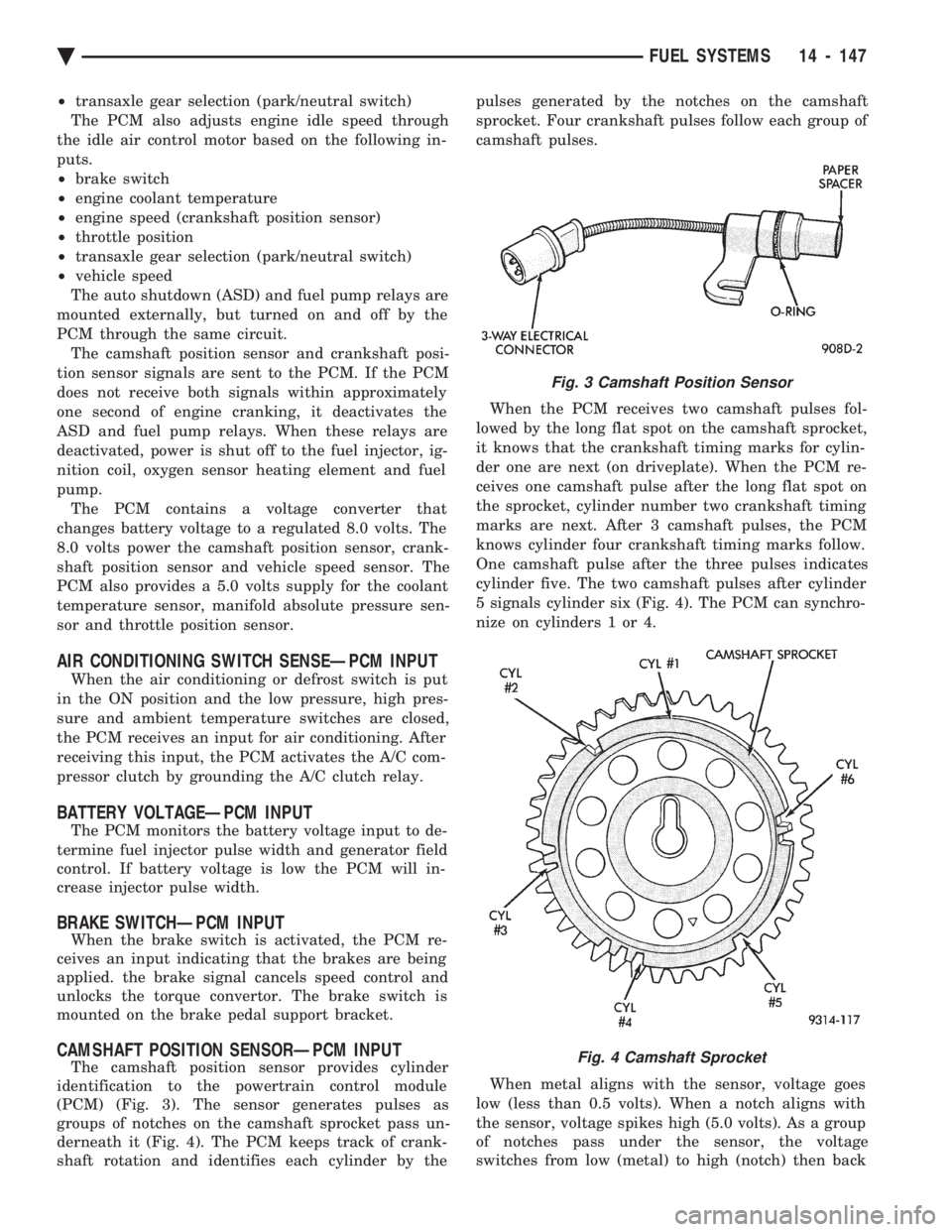
CAMSHAFT POSITION SENSORÐPCM INPUT
The camshaft position sensor provides cylinder
identification to the powertrain control module
(PCM) (Fig. 3). The sensor generates pulses as
groups of notches on the camshaft sprocket pass un-
derneath it (Fig. 4). The PCM keeps track of crank-
shaft rotation and identifies each cylinder by the pulses generated by the notches on the camshaft
sprocket. Four crankshaft pulses follow each group of
camshaft pulses.
When the PCM receives two camshaft pulses fol-
lowed by the long flat spot on the camshaft sprocket,
it knows that the crankshaft timing marks for cylin-
der one are next (on driveplate). When the PCM re-
ceives one camshaft pulse after the long flat spot on
the sprocket, cylinder number two crankshaft timing
marks are next. After 3 camshaft pulses, the PCM
knows cylinder four crankshaft timing marks follow.
One camshaft pulse after the three pulses indicates
cylinder five. The two camshaft pulses after cylinder
5 signals cylinder six (Fig. 4). The PCM can synchro-
nize on cylinders 1 or 4.
When metal aligns with the sensor, voltage goes
low (less than 0.5 volts). When a notch aligns with
the sensor, voltage spikes high (5.0 volts). As a group
of notches pass under the sensor, the voltage
switches from low (metal) to high (notch) then back
Fig. 3 Camshaft Position Sensor
Fig. 4 Camshaft Sprocket
Ä FUEL SYSTEMS 14 - 147
Page 1893 of 2438
the PCM determines crankshaft position, it begins
energizing the injectors in sequence.The auto shutdown (ASD) relay supplies battery
voltage to the injectors. The PCM provides the
ground path for the injectors. By switching the
ground path on and off, the PCM adjusts injector
pulse width. Pulse width is the amount of time the
injector is energized. The PCM adjusts injector pulse
width based on inputs it receives.
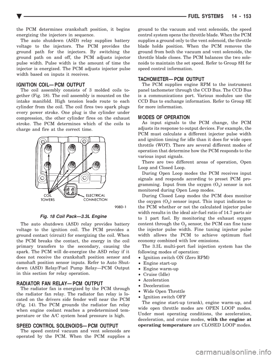
IGNITION COILÐPCM OUTPUT
The coil assembly consists of 3 molded coils to-
gether (Fig. 18). The coil assembly is mounted on the
intake manifold. High tension leads route to each
cylinder from the coil. The coil fires two spark plugs
every power stroke. One plug is the cylinder under
compression, the other cylinder fires on the exhaust
stroke. The PCM determines which of the coils to
charge and fire at the correct time.
The auto shutdown (ASD) relay provides battery
voltage to the ignition coil. The PCM provides a
ground contact (circuit) for energizing the coil. When
the PCM breaks the contact, the energy in the coil
primary transfers to the secondary, causing the
spark. The PCM will de-energize the ASD relay if it
does not receive the crankshaft position sensor and
camshaft position sensor inputs. Refer to Auto Shut-
down (ASD) Relay/Fuel Pump RelayÐPCM Output
in this section for relay operation.
RADIATOR FAN RELAYÐPCM OUTPUT
The radiator fan is energized by the PCM through
the radiator fan relay. The radiator fan relay is lo-
cated on the drivers side fender well near the PCM
(Fig. 14). The PCM grounds the radiator fan relay
when engine coolant reaches a predetermined tem-
perature or the A/C system head pressure is high.
SPEED CONTROL SOLENOIDSÐPCM OUTPUT
The speed control vacuum and vent solenoids are
operated by the PCM. When the PCM supplies a ground to the vacuum and vent solenoids, the speed
control system opens the throttle blade. When the PCM
supplies a ground only to the vent solenoid, the throttle
blade holds position. When the PCM removes the
ground from both the vacuum and vent solenoids, the
throttle blade closes. The PCM balances the two sole-
noids to maintain the set speed. Refer to Group 8H for
speed control information.
TACHOMETERÐPCM OUTPUT
The PCM supplies engine RPM to the instrument
panel tachometer through the CCD Bus. The CCD Bus
is a communications port. Various modules use the
CCD Bus to exchange information. Refer to Group 8E
for more information.
MODES OF OPERATION
As input signals to the PCM change, the PCM
adjusts its response to output devices. For example, the
PCM must calculate a different injector pulse width
and ignition timing for idle than it does for wide open
throttle (WOT). There are several different modes of
operation that determine how the PCM responds to the
various input signals. There are two different areas of operation, Open
Loop and Closed Loop. During Open Loop modes the PCM receives input
signals and responds according to preset PCM pro-
gramming. Input from the oxygen (O
2) sensor is not
monitored during Open Loop modes. During Closed Loop modes the PCM does monitor
the oxygen (O
2) sensor input. This input indicates to
the PCM whether or not the calculated injector pulse
width results in the ideal air-fuel ratio of 14.7 parts air
to 1 part fuel. By monitoring the exhaust oxygen
content through the O
2sensor, the PCM can fine tune
the injector pulse width. Fine tuning injector pulse
width allows the PCM to achieve optimum fuel
economy combined with low emissions. The 3.3L multi-port fuel injection system has the
following modes of operation:
² Ignition switch ON (Zero RPM)
² Engine start-up
² Engine warm-up
² Cruise (Idle)
² Acceleration
² Deceleration
² Wide Open Throttle
² Ignition switch OFF
The engine start-up (crank), engine warm-up, and
wide open throttle modes are OPEN LOOP modes.
Under most operating conditions, the acceleration,
deceleration, and cruise modes, with the engine at
operating temperature are CLOSED LOOP modes.
Fig. 18 Coil PackÐ3.3L Engine
Ä FUEL SYSTEMS 14 - 153