service interval CHEVROLET DYNASTY 1993 User Guide
[x] Cancel search | Manufacturer: CHEVROLET, Model Year: 1993, Model line: DYNASTY, Model: CHEVROLET DYNASTY 1993Pages: 2438, PDF Size: 74.98 MB
Page 1770 of 2438
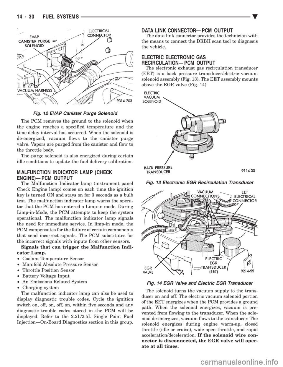
The PCM removes the ground to the solenoid when
the engine reaches a specified temperature and the
time delay interval has occurred. When the solenoid is
de-energized, vacuum flows to the canister purge
valve. Vapors are purged from the canister and flow to
the throttle body. The purge solenoid is also energized during certain
idle conditions to update the fuel delivery calibration.
MALFUNCTION INDICATOR LAMP (CHECK
ENGINE)ÐPCM OUTPUT
The Malfunction Indicator lamp (instrument panel
Check Engine lamp) comes on each time the ignition
key is turned ON and stays on for 3 seconds as a bulb
test. The malfunction indicator lamp warns the opera-
tor that the PCM has entered a Limp-in mode. During
Limp-in-Mode, the PCM attempts to keep the system
operational. The malfunction indicator lamp signals
the need for immediate service. In limp-in mode, the
PCM compensates for the failure of certain components
that send incorrect signals. The PCM substitutes for
the incorrect signals with inputs from other sensors. Signals that can trigger the Malfunction Indi-
cator Lamp.
² Coolant Temperature Sensor
² Manifold Absolute Pressure Sensor
² Throttle Position Sensor
² Battery Voltage Input
² An Emissions Related System
² Charging system
The malfunction indicator lamp can also be used to
display diagnostic trouble codes. Cycle the ignition
switch on, off, on, off, on, within five seconds and any
diagnostic trouble codes stored in the PCM will be
displayed. Refer to the 2.2L/2.5L Single Point Fuel
InjectionÐOn-Board Diagnostics section in this group.
DATA LINK CONNECTORÐPCM OUTPUT
The data link connector provides the technician with
the means to connect the DRBII scan tool to diagnosis
the vehicle.
ELECTRIC ELECTRONIC GAS
RECIRCULATIONÐPCM OUTPUT
The electronic exhaust gas recirculation transducer
(EET) is a back pressure transducer/electric vacuum
solenoid assembly (Fig. 13). The EET assembly mounts
above the EGR valve (Fig. 14).
The solenoid turns the vacuum supply to the trans-
ducer on and off. The electric vacuum solenoid portion
of the EET energizes when the PCM provides a ground
path. When the solenoid energizes, vacuum is pre-
vented from flowing to the transducer. When the sole-
noid de-energizes, vacuum flows to the transducer. The
solenoid energizes during engine warm-up, closed
throttle (idle or cruise), wide open throttle, and rapid
acceleration/deceleration. If the solenoid wire con-
nector is disconnected, the EGR valve will oper-
ate at all times.
Fig. 12 EVAP Canister Purge Solenoid
Fig. 13 Electronic EGR Recirculation Transducer
Fig. 14 EGR Valve and Electric EGR Transducer
14 - 30 FUEL SYSTEMS Ä
Page 1830 of 2438
sition, the PCM monitors the crankshaft position and
camshaft position sensor signals to determine engine
speed and ignition timing (coil dwell). If the PCM
does not receive the crankshaft position sensor and
camshaft position sensor signals when the ignition
switch is in the Run position, it de-energizes both re-
lays. When the relays are de-energized, battery volt-
age is not supplied to the fuel injector, ignition coil,
fuel pump and oxygen sensor heating element. The ASD relay and fuel pump relay are located in
the power distribution center (Fig. 16).
IDLE AIR CONTROL MOTORÐPCM OUTPUT
The idle air control motor is mounted on the throt-
tle body (Fig. 14). The PCM operates the motor. The
PCM adjusts engine idle speed through the idle air
control motor to compensate for engine load or ambi-
ent conditions. The throttle body has an air bypass passage that
provides air for the engine at idle (the throttle blade
is closed). The idle air control motor pintle protrudes
into the air bypass passage and regulates air flow
through it. The PCM adjusts engine idle speed by moving the
idle air control motor pintle in and out of the bypass
passage. The adjustments are based on inputs the
PCM receives. The inputs are from the throttle posi-
tion sensor, camshaft position sensor, crankshaft po-
sition sensor, coolant temperature sensor, and
various switch operations (brake and air condition-
ing). Deceleration die out is also prevented by in-
creasing airflow when the throttle is closed quickly
after a driving (speed) condition.
BAROMETRIC READ SOLENOIDÐPCM OUTPUT
The barometric pressure read solenoid is spliced
into the manifold absolute pressure (MAP) sensor
vacuum hose (Fig. 12). The barometric read solenoid
switches the pressure supply to the MAP sensor from
either barometric pressure (atmospheric) or manifold
vacuum. The PCM operates the solenoid. Atmospheric pressure is periodically supplied to
the MAP sensor to measure barometric pressure.
This occurs at closed throttle, once per throttle clo-
sure but no more often than once every 3 minutes
and within a specified RPM band. Barometric infor-
mation is used primarily for boost control and start
fuel enrichment at various altitudes.
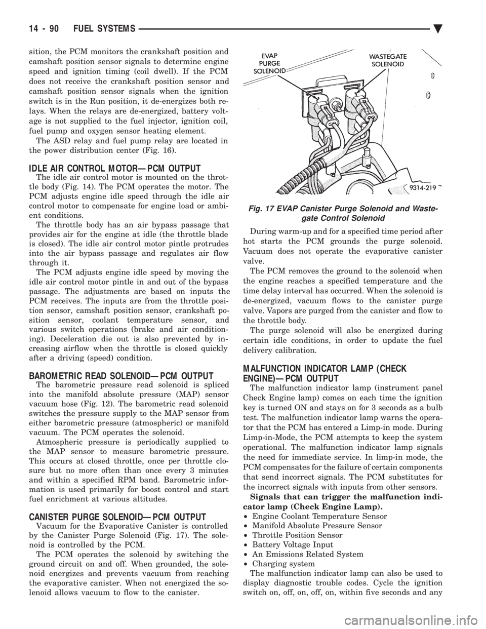
CANISTER PURGE SOLENOIDÐPCM OUTPUT
Vacuum for the Evaporative Canister is controlled
by the Canister Purge Solenoid (Fig. 17). The sole-
noid is controlled by the PCM. The PCM operates the solenoid by switching the
ground circuit on and off. When grounded, the sole-
noid energizes and prevents vacuum from reaching
the evaporative canister. When not energized the so-
lenoid allows vacuum to flow to the canister. During warm-up and for a specified time period after
hot starts the PCM grounds the purge solenoid.
Vacuum does not operate the evaporative canister
valve. The PCM removes the ground to the solenoid when
the engine reaches a specified temperature and the
time delay interval has occurred. When the solenoid is
de-energized, vacuum flows to the canister purge
valve. Vapors are purged from the canister and flow to
the throttle body. The purge solenoid will also be energized during
certain idle conditions, in order to update the fuel
delivery calibration.
MALFUNCTION INDICATOR LAMP (CHECK
ENGINE)ÐPCM OUTPUT
The malfunction indicator lamp (instrument panel
Check Engine lamp) comes on each time the ignition
key is turned ON and stays on for 3 seconds as a bulb
test. The malfunction indicator lamp warns the opera-
tor that the PCM has entered a Limp-in mode. During
Limp-in-Mode, the PCM attempts to keep the system
operational. The malfunction indicator lamp signals
the need for immediate service. In limp-in mode, the
PCM compensates for the failure of certain components
that send incorrect signals. The PCM substitutes for
the incorrect signals with inputs from other sensors. Signals that can trigger the malfunction indi-
cator lamp (Check Engine Lamp).
² Engine Coolant Temperature Sensor
² Manifold Absolute Pressure Sensor
² Throttle Position Sensor
² Battery Voltage Input
² An Emissions Related System
² Charging system
The malfunction indicator lamp can also be used to
display diagnostic trouble codes. Cycle the ignition
switch on, off, on, off, on, within five seconds and any
Fig. 17 EVAP Canister Purge Solenoid and Waste- gate Control Solenoid
14 - 90 FUEL SYSTEMS Ä
Page 2149 of 2438
WHEELSÐTIRES
CONTENTS
page page
SPECIFICATIONS ........................ 8
TIRE SERVICE PROCEDURES .............. 1 WHEELS SERVICE PROCEDURES
........... 6
TIRE SERVICE PROCEDURES INDEX
page page
Cleaning of Tires .......................... 1
General Information ........................ 1
Pressure Gauges ......................... 2
Radial-Ply Tires ........................... 1
Repairing Leaks .......................... 3
Rotation ................................ 3 Spare TireÐCompact
...................... 1
Tire Inflation Pressures ..................... 2
Tire Noise or Vibration ..................... 3
Tire Wear Patterns ........................ 3
Tread Wear Indicators ...................... 3
GENERAL INFORMATION
Throughout this group, references may be made to a
particular vehicle by letter or number designation. A
chart showing the breakdown of these designations is
included in the Introduction Section. Tires are designed for the vehicle and provide the
best overall performance for normal operation. The
ride and handling characteristics match the vehicle's
requirements. With proper care they will give excellent
reliability traction, skid resistance and tread life. They
have load carrying capacity, when properly inflated, to
operate at loads up to the specified Maximum Vehicle
Capacity. Driving habits have more effect on tire life than any
other factor. Careful drivers will obtain, in most cases,
much greater mileage than severe or careless drivers. A
few of the driving habits which will shorten the life of
any tire are:
² Rapid acceleration and deceleration
² Severe application of brakes
² High-speed driving
² Taking turns at excessive speeds
² Striking curbs and other obstacles
Radial ply tires can be more susceptible to irregular
tread wear. It is very important to follow the tire
rotation interval shown in the section on Tire
Rotation to achieve a greater tread life potential.
RADIAL-PLY TIRES
Radial-ply tires improve handling, tread life, and
ride quality and decrease rolling resistance. Radial-ply tires must always be used in sets of four
and under no circumstances should they be used on
the front only. However, they may be mixed with temporary spare tires when necessary,
but reduced speeds are recommended. Radial-ply tires have the same load carrying capac-
ity as other types of tires of the same size. They also
use the same recommended inflation pressures.
SPARE TIREÐCOMPACT
The compact spare tire is designed for emergency
use only. The original tire should be repaired and re-
installed at the first opportunity. Refer to Owner's
Manual for complete details.
TIRE CHAINS
Tire snow chains may be used on certainmodels.
Refer to Owner's Manual for more information.
CLEANING OF TIRES
Remove protective coating on tires before delivery
of vehicle, otherwise it could cause deterioration of
tires. Remove protective coating by applying warm wa-
ter, letting it soak one minute, and then scrubbing
the coating away with a soft bristle brush. Steam cleaning may also be used for cleaning.
DO NOT use gasoline or wire brush for cleaning.
DO NOT use mineral oil or an oil-based solvent.
Ä WHEELSÐTIRES 22 - 1
Page 2401 of 2438
EVAPORATION CONTROL SYSTEM
The evaporation control system prevents the emis-
sion of fuel tank vapors into the atmosphere. When fuel
evaporates in the fuel tank, the vapors pass through
vent hoses or tubes to a charcoal canister. The canister
temporarily holds the vapors. The powertrain control
module (PCM) allows intake manifold vacuum to draw
vapors into the combustion chambers during certain
operating conditions. The PCM uses the canister purge
solenoid to regulate vapor flow. On 2.2L and 2.5L TBI, 3.3L, and 3.8L engines,
manifold vacuum purges the vapors at idle as well as
off idle. These engines use a bi-level purge system. The
system uses 2 sources of vacuum remove fuel vapors
from the canister. Turbo III engines use a tri-level canister purge sys-
tem. In this system, fuel vapors are drawn into the
engine through the throttle body and air cleaner. Fuel
vapors are drawn in at closed throttle, part throttle,
and wide open throttle (in boost). The 2.5L MPI (flexible fuel AA-Body) and 3.0L have
a duty cycle purge system. The powertrain control
module PCM controls vapor flow by operating the duty
cycle EVAP purge solenoid. Refer to Duty Cycle EVAP
Purge Solenoid in this section. The evaporative system uses specially manu-
factured hoses. If they need replacement, only
use fuel resistant hose.
PRESSURE RELIEF/ROLLOVER VALVE
All vehicles have a combination pressure relief and
rollover valve. The dual function valve relieves fuel
tank pressure. The valve also prevents fuel flow
through the fuel tank vent valve hoses if the vehicle
accidentally rolls over. All vehicles pass a 360É rollover. The pressure relief valve opens at a certain pressure.
When fuel tank pressure increases above the cali-
brated pressure, the valve opens to release fuel tank
vapors pressure. The evaporative (charcoal) canister
stores the vapors. For pressure relief/rollover valve
service, refer to the Fuel Tank section of Group 14.
EVAPORATIVE CANISTER
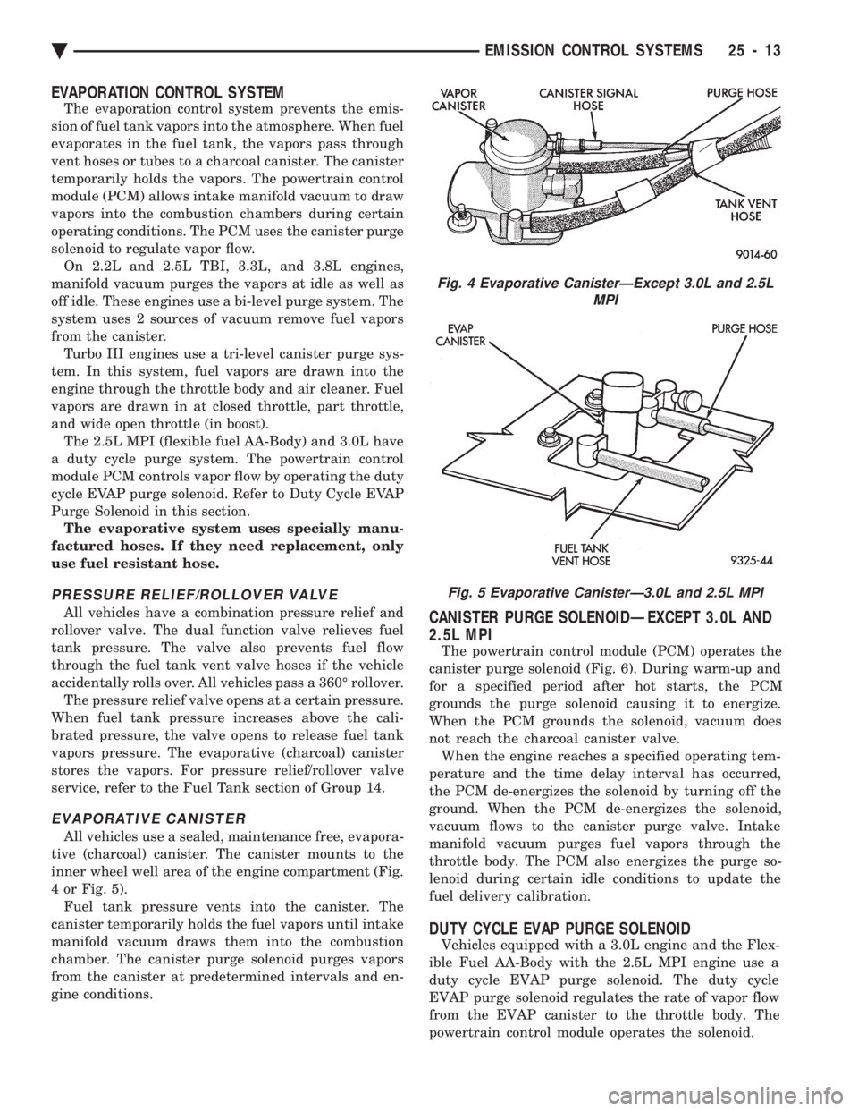
All vehicles use a sealed, maintenance free, evapora-
tive (charcoal) canister. The canister mounts to the
inner wheel well area of the engine compartment (Fig.
4 or Fig. 5). Fuel tank pressure vents into the canister. The
canister temporarily holds the fuel vapors until intake
manifold vacuum draws them into the combustion
chamber. The canister purge solenoid purges vapors
from the canister at predetermined intervals and en-
gine conditions.
CANISTER PURGE SOLENOIDÐEXCEPT 3.0L AND
2.5L MPI
The powertrain control module (PCM) operates the
canister purge solenoid (Fig. 6). During warm-up and
for a specified period after hot starts, the PCM
grounds the purge solenoid causing it to energize.
When the PCM grounds the solenoid, vacuum does
not reach the charcoal canister valve. When the engine reaches a specified operating tem-
perature and the time delay interval has occurred,
the PCM de-energizes the solenoid by turning off the
ground. When the PCM de-energizes the solenoid,
vacuum flows to the canister purge valve. Intake
manifold vacuum purges fuel vapors through the
throttle body. The PCM also energizes the purge so-
lenoid during certain idle conditions to update the
fuel delivery calibration.
DUTY CYCLE EVAP PURGE SOLENOID
Vehicles equipped with a 3.0L engine and the Flex-
ible Fuel AA-Body with the 2.5L MPI engine use a
duty cycle EVAP purge solenoid. The duty cycle
EVAP purge solenoid regulates the rate of vapor flow
from the EVAP canister to the throttle body. The
powertrain control module operates the solenoid.
Fig. 4 Evaporative CanisterÐExcept 3.0L and 2.5L MPI
Fig. 5 Evaporative CanisterÐ3.0L and 2.5L MPI
Ä EMISSION CONTROL SYSTEMS 25 - 13
Page 2404 of 2438
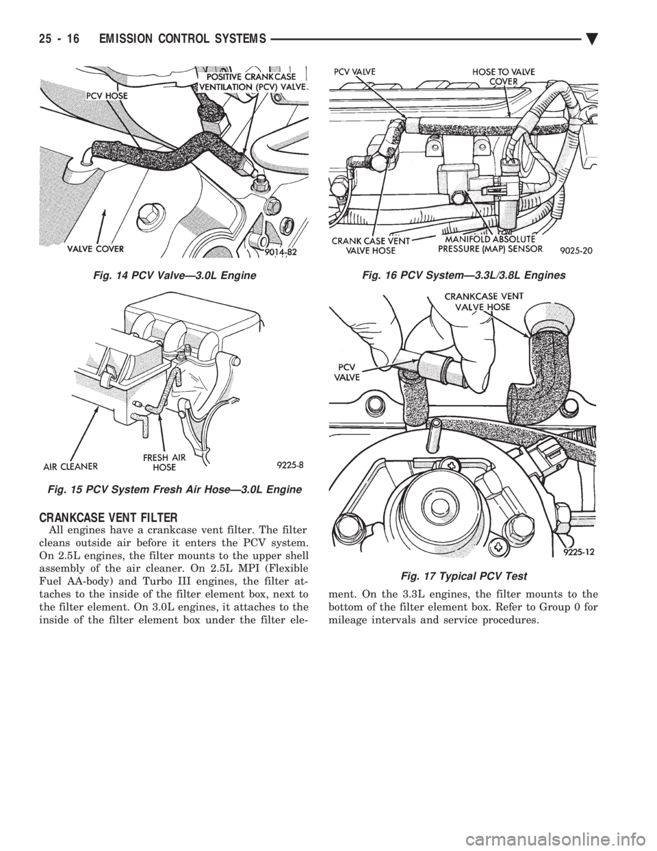
CRANKCASE VENT FILTER
All engines have a crankcase vent filter. The filter
cleans outside air before it enters the PCV system.
On 2.5L engines, the filter mounts to the upper shell
assembly of the air cleaner. On 2.5L MPI (Flexible
Fuel AA-body) and Turbo III engines, the filter at-
taches to the inside of the filter element box, next to
the filter element. On 3.0L engines, it attaches to the
inside of the filter element box under the filter ele- ment. On the 3.3L engines, the filter mounts to the
bottom of the filter element box. Refer to Group 0 for
mileage intervals and service procedures.
Fig. 14 PCV ValveÐ3.0L Engine
Fig. 15 PCV System Fresh Air HoseÐ3.0L Engine
Fig. 16 PCV SystemÐ3.3L/3.8L Engines
Fig. 17 Typical PCV Test
25 - 16 EMISSION CONTROL SYSTEMS Ä