ECU CHEVROLET DYNASTY 1993 Service Manual
[x] Cancel search | Manufacturer: CHEVROLET, Model Year: 1993, Model line: DYNASTY, Model: CHEVROLET DYNASTY 1993Pages: 2438, PDF Size: 74.98 MB
Page 22 of 2438
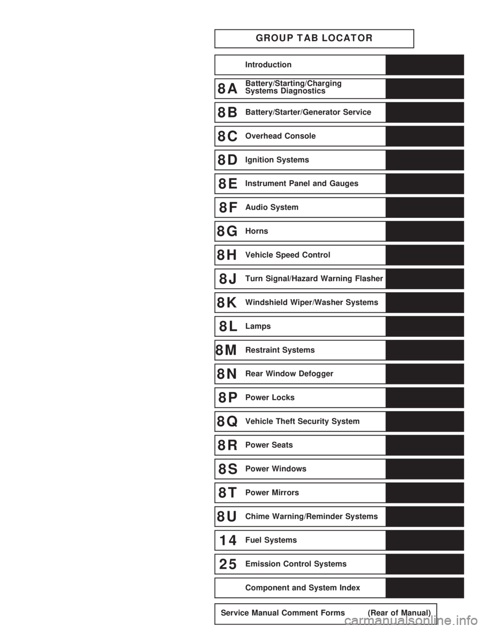
GROUP TAB LOCATOR
Introduction
8ABattery/Starting/Charging
Systems Diagnostics
8BBattery/Starter/Generator Service
8COverhead Console
8DIgnition Systems
8EInstrument Panel and Gauges
8FAudio System
8GHorns
8HVehicle Speed Control
8JTurn Signal/Hazard Warning Flasher
8KWindshield Wiper/Washer Systems
8LLamps
8MRestraint Systems
8NRear Window Defogger
8PPower Locks
8QVehicle Theft Security System
8RPower Seats
8SPower Windows
8TPower Mirrors
8UChime Warning/Reminder Systems
14Fuel Systems
25Emission Control Systems
Component and System Index
Service Manual Comment Forms (Rear of Manual)
Page 34 of 2438

VEHICLE THEFT SECURITY SYSTEM ..............8Q-1
WINDSHIELD WIPER AND WASHER SYSTEMS .......8K-1
GENERAL WIPER INFORMATION ...............8K-1
INTERMITTENT WINDSHIELD WIPER MOTOR AND SWITCH SERVICE PROCEDURES ............8K-12 WINDSHIELD WASHERS
................... 8K-17
WINDSHIELD WIPER BLADE AND ARM SERVICE PROCEDURES ......................... 8K-1
WINDSHIELD WIPER MOTOR AND LINKAGE ASSEMBLY SERVICE PROCEDURES ...........8K-3
Page 41 of 2438
(3) On disabled vehicle, place gear selector in park
or neutral and set park brake. Turn off all accesso-
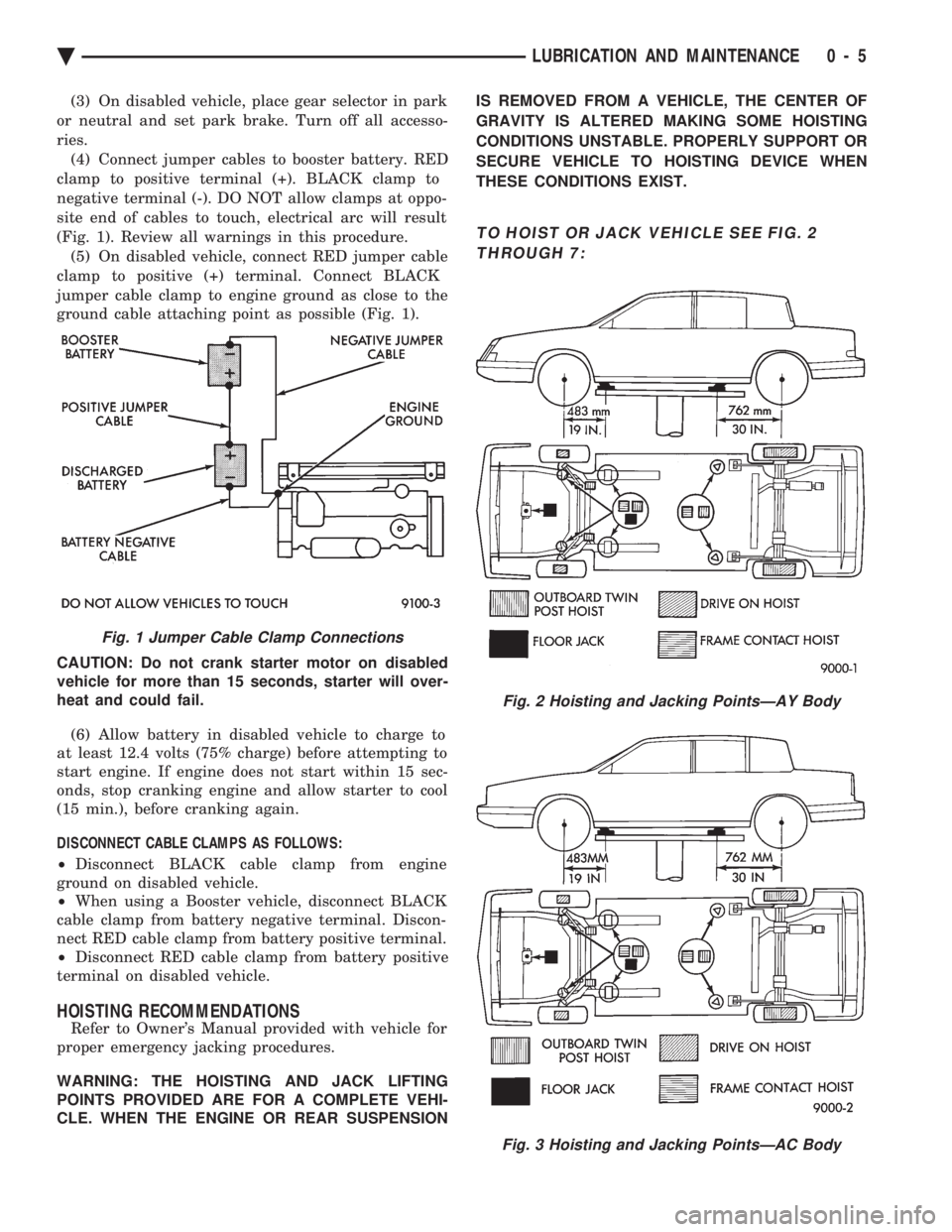
ries. (4) Connect jumper cables to booster battery. RED
clamp to positive terminal (+). BLACK clamp to
negative terminal (-). DO NOT allow clamps at oppo-
site end of cables to touch, electrical arc will result
(Fig. 1). Review all warnings in this procedure. (5) On disabled vehicle, connect RED jumper cable
clamp to positive (+) terminal. Connect BLACK
jumper cable clamp to engine ground as close to the
ground cable attaching point as possible (Fig. 1).
CAUTION: Do not crank starter motor on disabled
vehicle for more than 15 seconds, starter will over-
heat and could fail.
(6) Allow battery in disabled vehicle to charge to
at least 12.4 volts (75% charge) before attempting to
start engine. If engine does not start within 15 sec-
onds, stop cranking engine and allow starter to cool
(15 min.), before cranking again.
DISCONNECT CABLE CLAMPS AS FOLLOWS:
² Disconnect BLACK cable clamp from engine
ground on disabled vehicle.
² When using a Booster vehicle, disconnect BLACK
cable clamp from battery negative terminal. Discon-
nect RED cable clamp from battery positive terminal.
² Disconnect RED cable clamp from battery positive
terminal on disabled vehicle.
HOISTING RECOMMENDATIONS
Refer to Owner's Manual provided with vehicle for
proper emergency jacking procedures.
WARNING: THE HOISTING AND JACK LIFTING
POINTS PROVIDED ARE FOR A COMPLETE VEHI-
CLE. WHEN THE ENGINE OR REAR SUSPENSION IS REMOVED FROM A VEHICLE, THE CENTER OF
GRAVITY IS ALTERED MAKING SOME HOISTING
CONDITIONS UNSTABLE. PROPERLY SUPPORT OR
SECURE VEHICLE TO HOISTING DEVICE WHEN
THESE CONDITIONS EXIST.
TO HOIST OR JACK VEHICLE SEE FIG. 2 THROUGH 7:
Fig. 1 Jumper Cable Clamp Connections
Fig. 2 Hoisting and Jacking PointsÐAY Body
Fig. 3 Hoisting and Jacking PointsÐAC Body
Ä LUBRICATION AND MAINTENANCE 0 - 5
Page 43 of 2438
TOWING RECOMMENDATIONS
RECOMMENDED TOWING EQUIPMENT
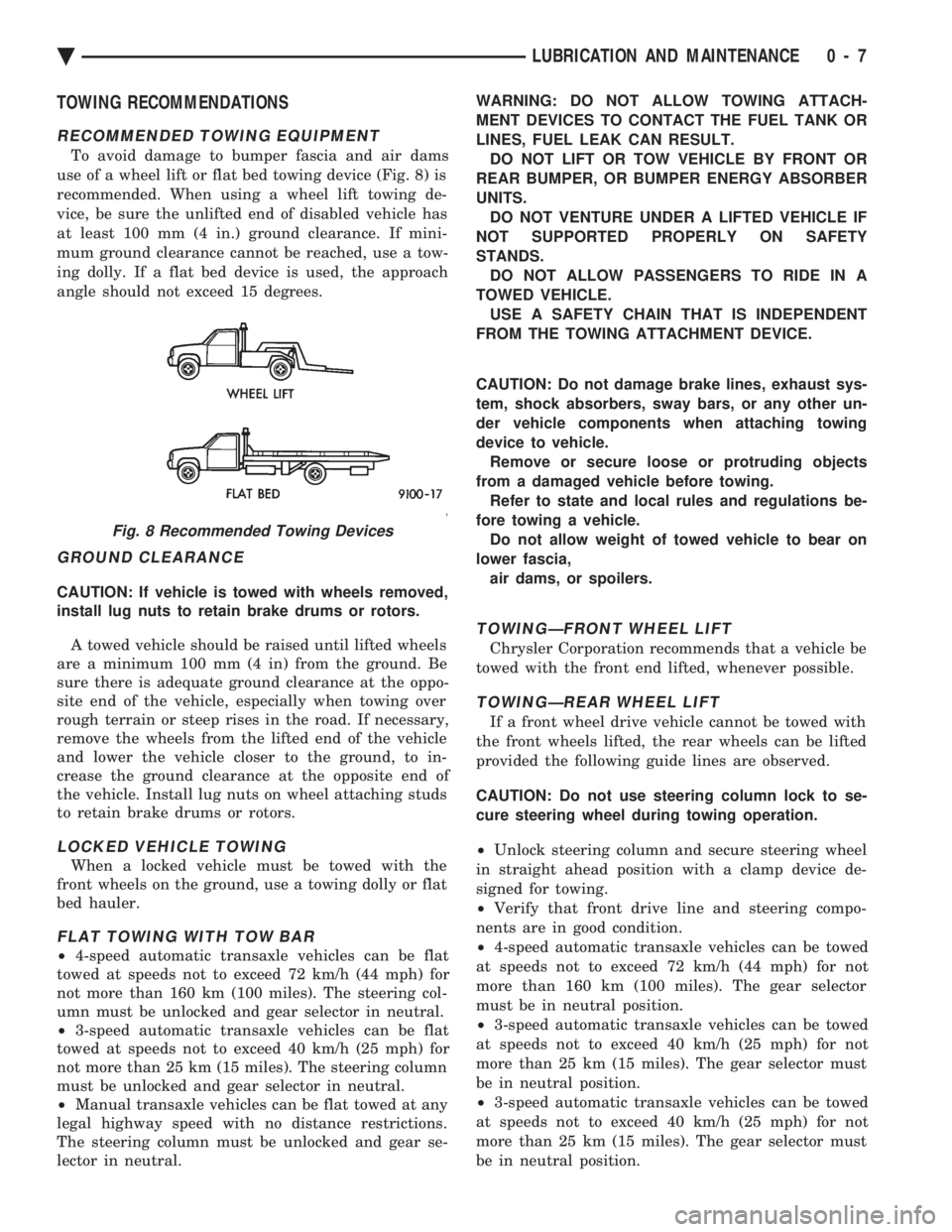
To avoid damage to bumper fascia and air dams
use of a wheel lift or flat bed towing device (Fig. 8) is
recommended. When using a wheel lift towing de-
vice, be sure the unlifted end of disabled vehicle has
at least 100 mm (4 in.) ground clearance. If mini-
mum ground clearance cannot be reached, use a tow-
ing dolly. If a flat bed device is used, the approach
angle should not exceed 15 degrees.
GROUND CLEARANCE
CAUTION: If vehicle is towed with wheels removed,
install lug nuts to retain brake drums or rotors.
A towed vehicle should be raised until lifted wheels
are a minimum 100 mm (4 in) from the ground. Be
sure there is adequate ground clearance at the oppo-
site end of the vehicle, especially when towing over
rough terrain or steep rises in the road. If necessary,
remove the wheels from the lifted end of the vehicle
and lower the vehicle closer to the ground, to in-
crease the ground clearance at the opposite end of
the vehicle. Install lug nuts on wheel attaching studs
to retain brake drums or rotors.
LOCKED VEHICLE TOWING
When a locked vehicle must be towed with the
front wheels on the ground, use a towing dolly or flat
bed hauler.
FLAT TOWING WITH TOW BAR
² 4-speed automatic transaxle vehicles can be flat
towed at speeds not to exceed 72 km/h (44 mph) for
not more than 160 km (100 miles). The steering col-
umn must be unlocked and gear selector in neutral.
² 3-speed automatic transaxle vehicles can be flat
towed at speeds not to exceed 40 km/h (25 mph) for
not more than 25 km (15 miles). The steering column
must be unlocked and gear selector in neutral.
² Manual transaxle vehicles can be flat towed at any
legal highway speed with no distance restrictions.
The steering column must be unlocked and gear se-
lector in neutral. WARNING: DO NOT ALLOW TOWING ATTACH-
MENT DEVICES TO CONTACT THE FUEL TANK OR
LINES, FUEL LEAK CAN RESULT. DO NOT LIFT OR TOW VEHICLE BY FRONT OR
REAR BUMPER, OR BUMPER ENERGY ABSORBER
UNITS. DO NOT VENTURE UNDER A LIFTED VEHICLE IF
NOT SUPPORTED PROPERLY ON SAFETY
STANDS. DO NOT ALLOW PASSENGERS TO RIDE IN A
TOWED VEHICLE. USE A SAFETY CHAIN THAT IS INDEPENDENT
FROM THE TOWING ATTACHMENT DEVICE.
CAUTION: Do not damage brake lines, exhaust sys-
tem, shock absorbers, sway bars, or any other un-
der vehicle components when attaching towing
device to vehicle. Remove or secure loose or protruding objects
from a damaged vehicle before towing. Refer to state and local rules and regulations be-
fore towing a vehicle. Do not allow weight of towed vehicle to bear on
lower fascia, air dams, or spoilers.
TOWINGÐFRONT WHEEL LIFT
Chrysler Corporation recommends that a vehicle be
towed with the front end lifted, whenever possible.
TOWINGÐREAR WHEEL LIFT
If a front wheel drive vehicle cannot be towed with
the front wheels lifted, the rear wheels can be lifted
provided the following guide lines are observed.
CAUTION: Do not use steering column lock to se-
cure steering wheel during towing operation.
² Unlock steering column and secure steering wheel
in straight ahead position with a clamp device de-
signed for towing.
² Verify that front drive line and steering compo-
nents are in good condition.
² 4-speed automatic transaxle vehicles can be towed
at speeds not to exceed 72 km/h (44 mph) for not
more than 160 km (100 miles). The gear selector
must be in neutral position.
² 3-speed automatic transaxle vehicles can be towed
at speeds not to exceed 40 km/h (25 mph) for not
more than 25 km (15 miles). The gear selector must
be in neutral position.
² 3-speed automatic transaxle vehicles can be towed
at speeds not to exceed 40 km/h (25 mph) for not
more than 25 km (15 miles). The gear selector must
be in neutral position.
Fig. 8 Recommended Towing Devices
Ä LUBRICATION AND MAINTENANCE 0 - 7
Page 47 of 2438
tifreeze to achieve adequate protection. A mix table
on the coolant container indicates the amount of an-
tifreeze required to winterize the cooling system
based on the capacity, see Capacity Chart in General
Information section of this group.
SELECTING ANTIFREEZE
Chrysler Corporation recommends Mopar Anti-
freeze/Summer Coolant, or equivalent be used to win-
terize and protect cooling system.
RADIATOR CAP
The radiator cap must be secure to provide proper
pressure release and coolant recovery. Inspect and
test radiator cap when cooling system service is per-
formed or when problem is suspected.
COOLING SYSTEM SERVICE
The cooling system should be drained, flushed and
filled with the proper coolant mixture at the inter-
vals described in the Lubrication and Maintenance
Schedules. Refer to General Information section of
this group. For proper service instructions see Group
7, Cooling System.
ENGINE AIR CLEANER
The engine air cleaner should be serviced at the in-
tervals described in the Lubrication and Mainte-
nance Schedules. Refer to General Information
section of this group. Additional information can be
found in Group 14, Fuel System and Group 25, Emis-
sion System. Inspect all air cleaner hoses or tubes for
damage or leaks when other engine compartment
service is performed. Replace faulty components.
AIR CLEANER SERVICE
CAUTION: The air cleaner cover must be installed
properly for the emissions system and engine con-
troller to function correctly. Do not immerse paper air filter element or temper-
ature sensor in cleaning solvents, damage can re-
sult.
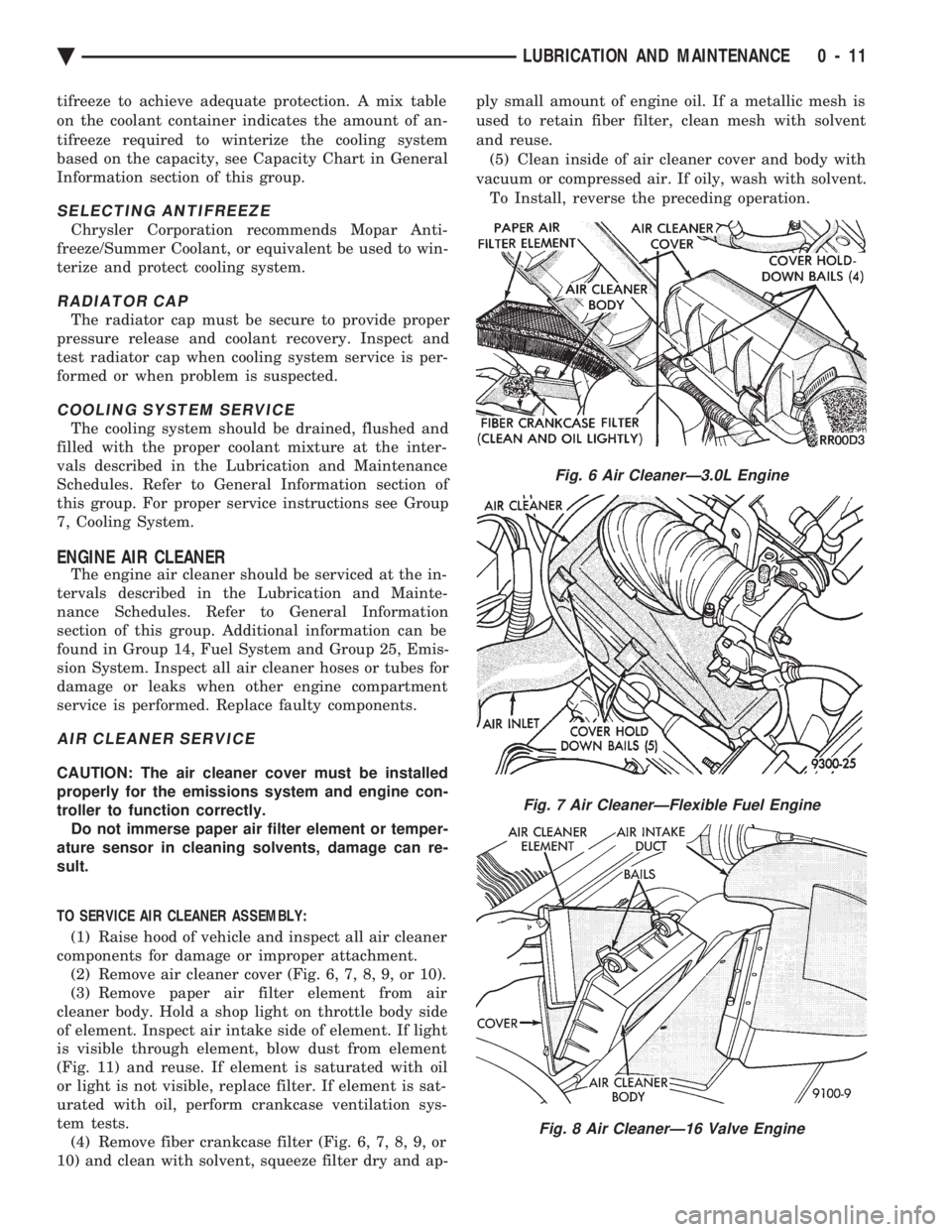
TO SERVICE AIR CLEANER ASSEMBLY: (1) Raise hood of vehicle and inspect all air cleaner
components for damage or improper attachment. (2) Remove air cleaner cover (Fig. 6, 7, 8, 9, or 10).
(3) Remove paper air filter element from air
cleaner body. Hold a shop light on throttle body side
of element. Inspect air intake side of element. If light
is visible through element, blow dust from element
(Fig. 11) and reuse. If element is saturated with oil
or light is not visible, replace filter. If element is sat-
urated with oil, perform crankcase ventilation sys-
tem tests. (4) Remove fiber crankcase filter (Fig. 6, 7, 8, 9, or
10) and clean with solvent, squeeze filter dry and ap- ply small amount of engine oil. If a metallic mesh is
used to retain fiber filter, clean mesh with solvent
and reuse.
(5) Clean inside of air cleaner cover and body with
vacuum or compressed air. If oily, wash with solvent. To Install, reverse the preceding operation.
Fig. 6 Air CleanerÐ3.0L Engine
Fig. 7 Air CleanerÐFlexible Fuel Engine
Fig. 8 Air CleanerÐ16 Valve Engine
Ä LUBRICATION AND MAINTENANCE 0 - 11
Page 55 of 2438
CHASSIS AND BODY INDEX
page page
Body Lubrication ......................... 22
Brakes ................................ 21
Headlamps ............................. 22
Lower Ball Joints ......................... 19 Power Steering
.......................... 19
Rear Wheel Bearings ..................... 20
Steering Linkage ......................... 19
STEERING LINKAGE
INSPECTION
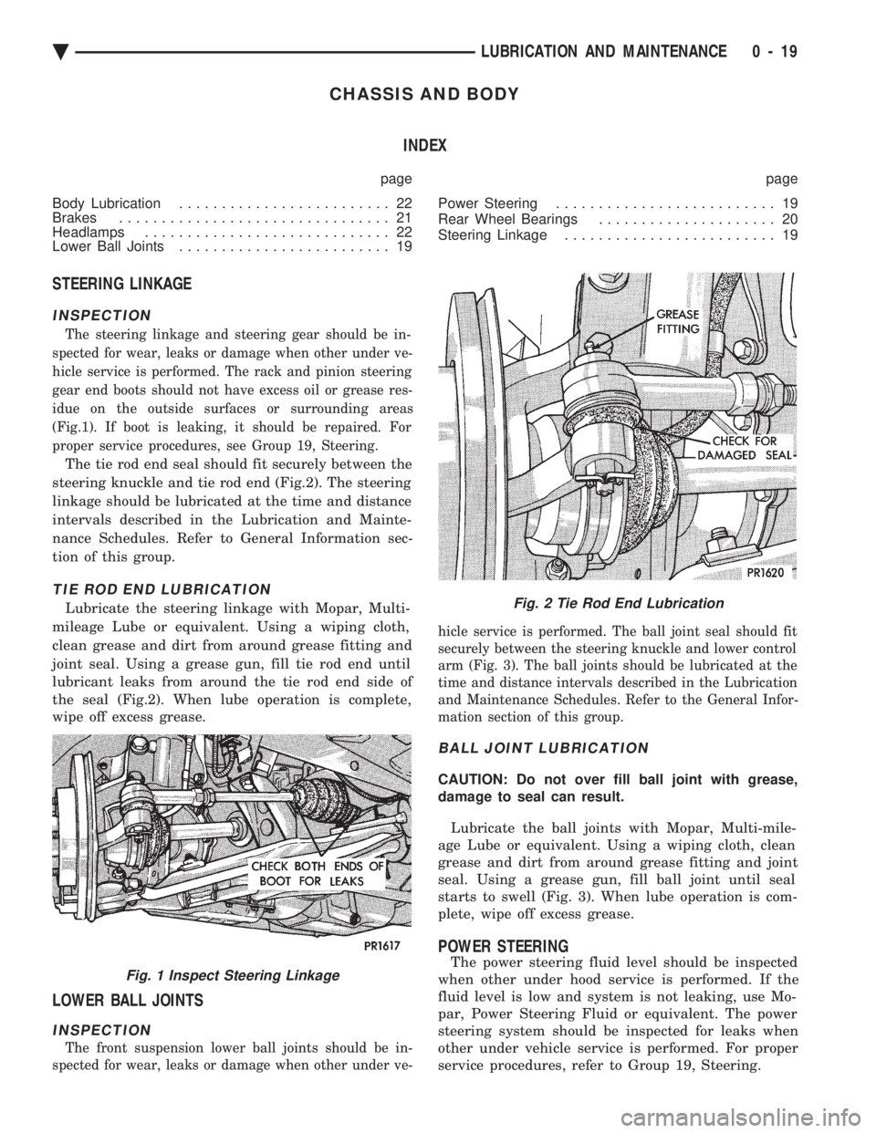
The steering linkage and steering gear should be in-
spected for wear, leaks or damage when other under ve-
hicle service is performed. The rack and pinion steering
gear end boots should not have excess oil or grease res-
idue on the outside surfaces or surrounding areas
(Fig.1). If boot is leaking, it should be repaired. For
proper service procedures, see Group 19, Steering.
The tie rod end seal should fit securely between the
steering knuckle and tie rod end (Fig.2). The steering
linkage should be lubricated at the time and distance
intervals described in the Lubrication and Mainte-
nance Schedules. Refer to General Information sec-
tion of this group.
TIE ROD END LUBRICATION
Lubricate the steering linkage with Mopar, Multi-
mileage Lube or equivalent. Using a wiping cloth,
clean grease and dirt from around grease fitting and
joint seal. Using a grease gun, fill tie rod end until
lubricant leaks from around the tie rod end side of
the seal (Fig.2). When lube operation is complete,
wipe off excess grease.
LOWER BALL JOINTS
INSPECTION
The front suspension lower ball joints should be in-
spected for wear, leaks or damage when other under ve- hicle service is performed. The ball joint seal should fit
securely between the steering knuckle and lower control
arm (Fig. 3). The ball joints should be lubricated at the
time and distance intervals described in the Lubrication
and Maintenance Schedules. Refer to the General Infor-
mation section of this group.
BALL JOINT LUBRICATION
CAUTION: Do not over fill ball joint with grease,
damage to seal can result.
Lubricate the ball joints with Mopar, Multi-mile-
age Lube or equivalent. Using a wiping cloth, clean
grease and dirt from around grease fitting and joint
seal. Using a grease gun, fill ball joint until seal
starts to swell (Fig. 3). When lube operation is com-
plete, wipe off excess grease.
POWER STEERING
The power steering fluid level should be inspected
when other under hood service is performed. If the
fluid level is low and system is not leaking, use Mo-
par, Power Steering Fluid or equivalent. The power
steering system should be inspected for leaks when
other under vehicle service is performed. For proper
service procedures, refer to Group 19, Steering.Fig. 1 Inspect Steering Linkage
Fig. 2 Tie Rod End Lubrication
Ä LUBRICATION AND MAINTENANCE 0 - 19
Page 74 of 2438
the lower clamps and bolts. The center offset in the
sway bar should be oriented toward the front of the
vehicle (Fig. 16)(3) Position bushing retainers on lower control arms
and install bolts (Fig. 16). (4) With lower control arms raised to design height,
tighten all retainer attaching bolts to 70 N Im (50 ft.
lbs.) torque. (5) Lower vehicle.
KNUCKLE (FRONT SUSPENSION)
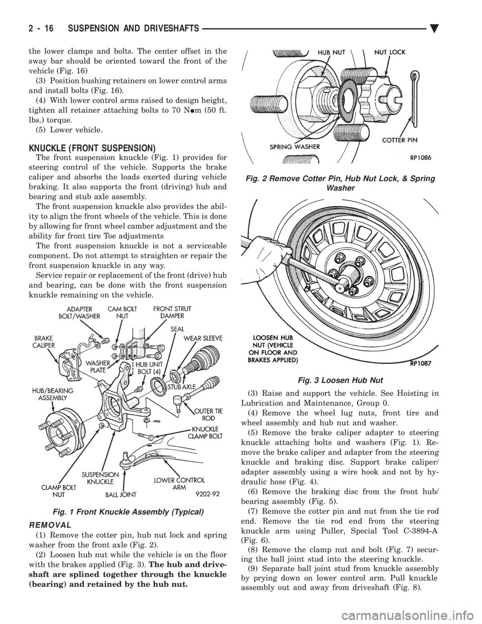
The front suspension knuckle (Fig. 1) provides for
steering control of the vehicle. Supports the brake
caliper and absorbs the loads exerted during vehicle
braking. It also supports the front (driving) hub and
bearing and stub axle assembly. The front suspension knuckle also provides the abil-
ity to align the front wheels of the vehicle. This is done
by allowing for front wheel camber adjustment and the
ability for front tire Toe adjustments The front suspension knuckle is not a serviceable
component. Do not attempt to straighten or repair the
front suspension knuckle in any way. Service repair or replacement of the front (drive) hub
and bearing, can be done with the front suspension
knuckle remaining on the vehicle.
REMOVAL
(1) Remove the cotter pin, hub nut lock and spring
washer from the front axle (Fig. 2). (2) Loosen hub nut while the vehicle is on the floor
with the brakes applied (Fig. 3). The hub and drive-
shaft are splined together through the knuckle
(bearing) and retained by the hub nut. (3) Raise and support the vehicle. See Hoisting in
Lubrication and Maintenance, Group 0. (4) Remove the wheel lug nuts, front tire and
wheel assembly and hub nut and washer. (5) Remove the brake caliper adapter to steering
knuckle attaching bolts and washers (Fig. 1). Re-
move the brake caliper and adapter from the steering
knuckle and braking disc. Support brake caliper/
adapter assembly using a wire hook and not by hy-
draulic hose (Fig. 4). (6) Remove the braking disc from the front hub/
bearing assembly (Fig. 5). (7) Remove the cotter pin and nut from the tie rod
end. Remove the tie rod end from the steering
knuckle arm using Puller, Special Tool C-3894-A
(Fig. 6). (8) Remove the clamp nut and bolt (Fig. 7) secur-
ing the ball joint stud into the steering knuckle. (9) Separate ball joint stud from knuckle assembly
by prying down on lower control arm. Pull knuckle
assembly out and away from driveshaft (Fig. 8).
Fig. 2 Remove Cotter Pin, Hub Nut Lock, & Spring Washer
Fig. 3 Loosen Hub Nut
Fig. 1 Front Knuckle Assembly (Typical)
2 - 16 SUSPENSION AND DRIVESHAFTS Ä
Page 79 of 2438
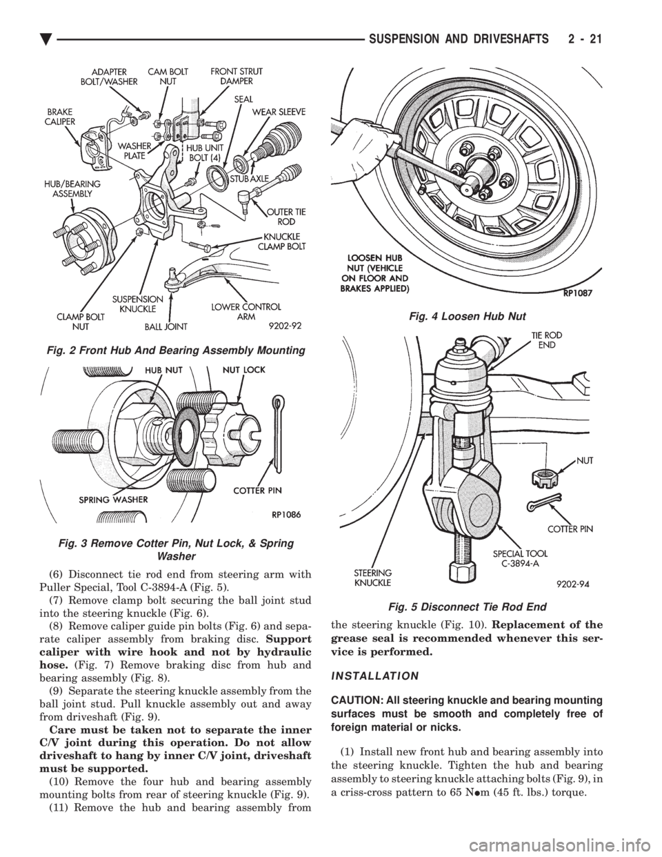
(6) Disconnect tie rod end from steering arm with
Puller Special, Tool C-3894-A (Fig. 5). (7) Remove clamp bolt securing the ball joint stud
into the steering knuckle (Fig. 6). (8) Remove caliper guide pin bolts (Fig. 6) and sepa-
rate caliper assembly from braking disc. Support
caliper with wire hook and not by hydraulic
hose. (Fig. 7) Remove braking disc from hub and
bearing assembly (Fig. 8). (9) Separate the steering knuckle assembly from the
ball joint stud. Pull knuckle assembly out and away
from driveshaft (Fig. 9). Care must be taken not to separate the inner
C/V joint during this operation. Do not allow
driveshaft to hang by inner C/V joint, driveshaft
must be supported. (10) Remove the four hub and bearing assembly
mounting bolts from rear of steering knuckle (Fig. 9). (11) Remove the hub and bearing assembly from the steering knuckle (Fig. 10).
Replacement of the
grease seal is recommended whenever this ser-
vice is performed.
INSTALLATION
CAUTION: All steering knuckle and bearing mounting
surfaces must be smooth and completely free of
foreign material or nicks.
(1) Install new front hub and bearing assembly into
the steering knuckle. Tighten the hub and bearing
assembly to steering knuckle attaching bolts (Fig. 9), in
a criss-cross pattern to 65 N Im (45 ft. lbs.) torque.
Fig. 2 Front Hub And Bearing Assembly Mounting
Fig. 3 Remove Cotter Pin, Nut Lock, & Spring
Washer
Fig. 4 Loosen Hub Nut
Fig. 5 Disconnect Tie Rod End
Ä SUSPENSION AND DRIVESHAFTS 2 - 21
Page 85 of 2438
DRIVESHAFT IDENTIFICATION
Driveshafts are identified by the manufacturer. Vehi-
cles can be equipped with any of these driveshaft as-
semblies. Each assembly can be identified as shown in
(Fig. 2).
SERVICE PROCEDURES
Procedures for the removal and installation of the
driveshafts are essentially the same for all front
wheel drive vehicles. Each driveshaft has a spring
within the inboard Tripod C/V joint that maintains
constant engagement with the transaxle. This allows
the drive shaft to be removed without dismantling
part of the transaxle.
CAUTION: Boot sealing is vital to retain special lu-
bricants and to prevent foreign contaminants from
entering the C/V joint. Mishandling, such as allow-
ing the assemblies to dangle unsupported, pulling
or pushing the ends can cut boots or damage C/V
joints. During removal and installation procedures
always support both ends of the driveshaft to pre-
vent damage.
DRIVESHAFTS, REMOVE INSTALL
HUB NUT REMOVAL
Hub nut removal and installation is the same for
all front wheel drive vehicles. For installation see
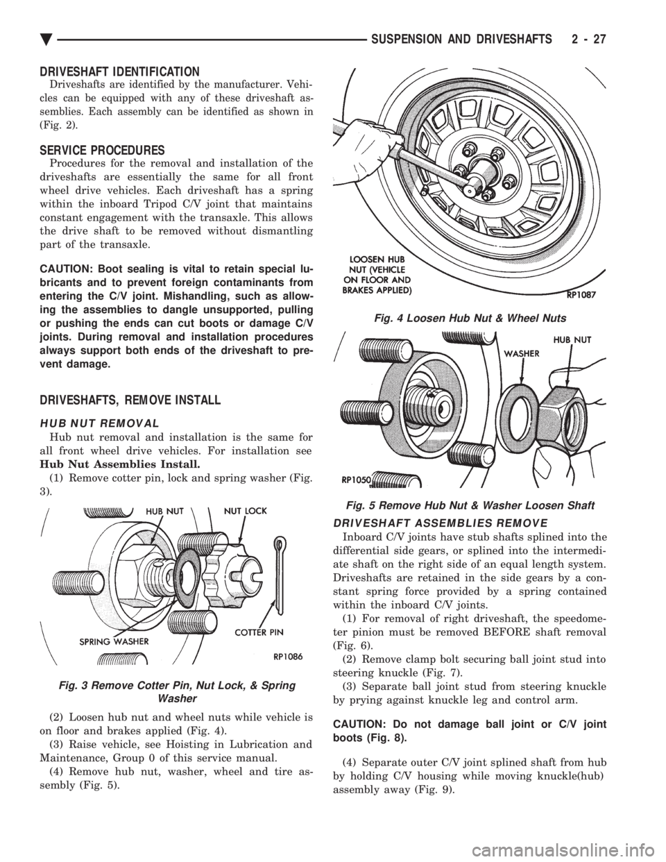
Hub Nut Assemblies Install. (1) Remove cotter pin, lock and spring washer (Fig.
3).
(2) Loosen hub nut and wheel nuts while vehicle is
on floor and brakes applied (Fig. 4). (3) Raise vehicle, see Hoisting in Lubrication and
Maintenance, Group 0 of this service manual. (4) Remove hub nut, washer, wheel and tire as-
sembly (Fig. 5).
DRIVESHAFT ASSEMBLIES REMOVE
Inboard C/V joints have stub shafts splined into the
differential side gears, or splined into the intermedi-
ate shaft on the right side of an equal length system.
Driveshafts are retained in the side gears by a con-
stant spring force provided by a spring contained
within the inboard C/V joints. (1) For removal of right driveshaft, the speedome-
ter pinion must be removed BEFORE shaft removal
(Fig. 6). (2) Remove clamp bolt securing ball joint stud into
steering knuckle (Fig. 7). (3) Separate ball joint stud from steering knuckle
by prying against knuckle leg and control arm.
CAUTION: Do not damage ball joint or C/V joint
boots (Fig. 8). (4) Separate outer C/V joint splined shaft from hub
by holding C/V housing while moving knuckle(hub)
assembly away (Fig. 9).
Fig. 3 Remove Cotter Pin, Nut Lock, & Spring Washer
Fig. 4 Loosen Hub Nut & Wheel Nuts
Fig. 5 Remove Hub Nut & Washer Loosen Shaft
Ä SUSPENSION AND DRIVESHAFTS 2 - 27
Page 86 of 2438
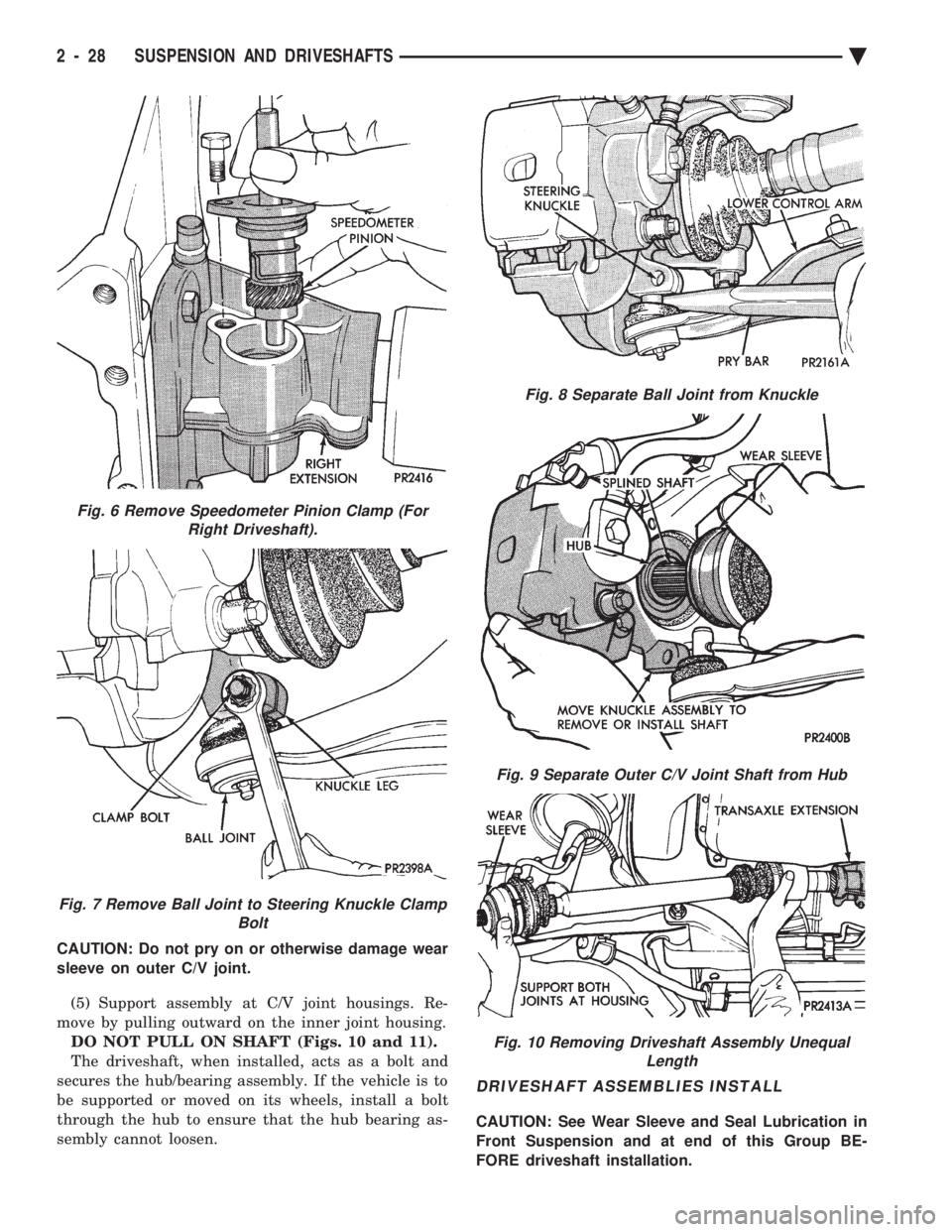
CAUTION: Do not pry on or otherwise damage wear
sleeve on outer C/V joint. (5) Support assembly at C/V joint housings. Re-
move by pulling outward on the inner joint housing. DO NOT PULL ON SHAFT (Figs. 10 and 11).
The driveshaft, when installed, acts as a bolt and
secures the hub/bearing assembly. If the vehicle is to
be supported or moved on its wheels, install a bolt
through the hub to ensure that the hub bearing as-
sembly cannot loosen.
DRIVESHAFT ASSEMBLIES INSTALL
CAUTION: See Wear Sleeve and Seal Lubrication in
Front Suspension and at end of this Group BE-
FORE driveshaft installation.
Fig. 6 Remove Speedometer Pinion Clamp (For Right Driveshaft).
Fig. 7 Remove Ball Joint to Steering Knuckle Clamp Bolt
Fig. 8 Separate Ball Joint from Knuckle
Fig. 9 Separate Outer C/V Joint Shaft from Hub
Fig. 10 Removing Driveshaft Assembly UnequalLength
2 - 28 SUSPENSION AND DRIVESHAFTS Ä