stop start CHEVROLET DYNASTY 1993 User Guide
[x] Cancel search | Manufacturer: CHEVROLET, Model Year: 1993, Model line: DYNASTY, Model: CHEVROLET DYNASTY 1993Pages: 2438, PDF Size: 74.98 MB
Page 305 of 2438
(4) Provide communication to the DRB II while in
the Antilock brakes diagnostic mode. The CAB continuously monitors the speed of each
wheel, through the signals generated at the Wheel
Speed Sensors. This is used to determine if any
wheel of the vehicle is beginning to lock-up (skid)
when the brakes are applied. When a wheel locking
tendency is detected during brake apply. The CAB
commands the appropriate Build/Decay valves to
modulate brake fluid pressure in some or all of the
hydraulic circuits. The CAB continues to control
pressure in individual hydraulic circuits until a lock-
ing tendency is no longer present. The ABS system is constantly monitored by the
CAB for proper operation. If the CAB detects a fault,
it will turn on the Amber Antilock Warning Lamp
and disable the ABS brake system. The normal Non
ABS brake system will remain operational. The CAB contains a self-diagnostic program which
will turn on the Amber Antilock Warning Lamp
when a system fault is detected. Faults are stored in
a diagnostic program memory. There are 16 fault
codes which may be stored in the CAB and displayed
through the DRB II. These fault codes will remain in
the CAB memory even after the ignition has been
turned off. The fault codes can be cleared by using
the DRB II diagnostics tester, or they will be auto-
matically cleared from the memory after (50) ignition
switch on/off cycles.
CONTROLLER ANTILOCK BRAKE (INPUTS)
² Four wheel speed sensors.
² Stop lamp switch.
² Ignition switch.
² System relay voltage.
² Ground.
² Pump/Motor Relay Monitor
² Diagnostics Communications
CONTROLLER ANTILOCK BRAKE (OUTPUTS)
²4 Build/Decay valves.
² Antilock warning lamp.
² System relay actuation.
² Diagnostic communication.
² Pump/Motor relay actuation
DIAGNOSTIC CONNECTOR
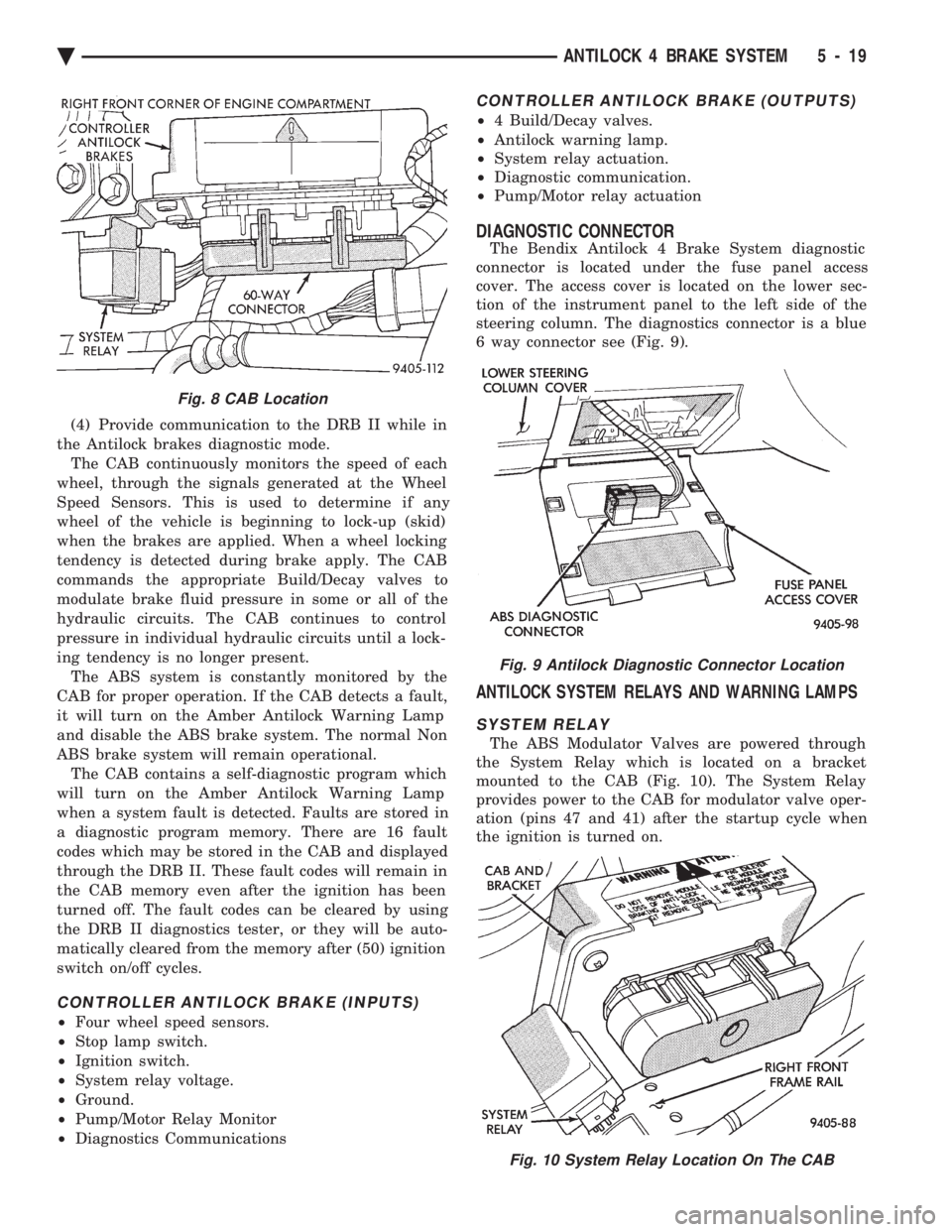
The Bendix Antilock 4 Brake System diagnostic
connector is located under the fuse panel access
cover. The access cover is located on the lower sec-
tion of the instrument panel to the left side of the
steering column. The diagnostics connector is a blue
6 way connector see (Fig. 9).
ANTILOCK SYSTEM RELAYS AND WARNING LAMPS
SYSTEM RELAY
The ABS Modulator Valves are powered through
the System Relay which is located on a bracket
mounted to the CAB (Fig. 10). The System Relay
provides power to the CAB for modulator valve oper-
ation (pins 47 and 41) after the startup cycle when
the ignition is turned on.
Fig. 8 CAB Location
Fig. 9 Antilock Diagnostic Connector Location
Fig. 10 System Relay Location On The CAB
Ä ANTILOCK 4 BRAKE SYSTEM 5 - 19
Page 310 of 2438
manual. May result in contact with moving parts or
over extension of cables, resulting in component fail-
ure and an open circuit.
MECHANICAL DIAGNOSTICS AND SERVICE
PROCEDURES
SPECIAL SERVICE TOOL
Some diagnostic procedures in this section require
the use of the DRB diagnostics tester. The proper ap-
plication and procedures for the use of this tool are
described below.
DRB DIAGNOSTIC TESTER
Some of the diagnostic procedures that are ex-
plained in this section require the use of the DRB Di-
agnostics Tester to insure that proper diagnostics are
performed. Refer to those sections for proper testing
procedures and the DRB operators manual for its
proper operational information.
INTERMITTENT FAULTS
As with virtually any electronic system, intermit-
tent faults in the ABS system may be difficult to ac-
curately diagnose. Most intermittent faults are caused by faulty elec-
trical connections or wiring. When an intermittent
fault is encountered, check suspect circuits for: (1) Poor mating of wiring harness connector halves
or terminals not fully seated in the connector body. (2) Improperly formed or damaged terminals. All
connector terminals in a suspect circuit should be
checked and carefully reformed to increase contact
tension with its mating terminal. (3) Poor terminal to wire connection. This requires
removing the terminal from the connector body to in-
spect. (4) Pin presence in the connector assembly
(5) Connector push-in, spread, and corrosion.
If a visual check does not find the cause of the
problem, operate the car in an attempt to duplicate
the condition and record the set Fault code. Most failures of the ABS system will disable the
Antilock function for the entire ignition cycle even if
the fault clears before key-off. There are some failure
conditions, however, which will allow ABS operation
to resume during the ignition cycle in which it oc-
curred, if the failure condition is no longer present.
The following conditions may result in intermittent
illumination of the Amber Antilock Warning Lamp.
All other failures will cause the lamp to remain on
until the ignition switch is turned off. Circuits in-
volving these inputs to the CAB should be investi-
gated if a complaint of intermittent warning system
operation is encountered. (1) Low system voltage: If Low System Voltage is
detected by the CAB, the CAB will turn on the Am-
ber Antilock Warning Lamp until normal system voltage is achieved. Once normal voltage is seen at
the CAB, normal operation resumes.
(2) Antilock system and pump/motor relay. If the
relays fail to make the ground circuit connection or
has an intermittent ground. The CAB will turn on
the Amber Antilock Warning Light. (3) Excess decay, an extended pressure decay pe-
riod, will turn on the Amber Antilock Warning Light
until the vehicle comes to a complete stop. Additionally, any condition which results in inter-
ruption of electrical current to the CAB or modulator
assembly, may cause the Amber Antilock Warning
Lamp to turn on intermittently.
ABS BRAKE SYSTEM DIAGNOSTIC FEATURES
ABS SYSTEM SELF DIAGNOSIS
The ABS system is equipped with a self diagnostic
capability which may be used to assist in isolation of
ABS faults. The features of the self diagnostics sys-
tem are described below.
START-UP CYCLE
The self diagnostic ABS start up cycle begins when
the ignition switch is turned to the on position. An
electrical check is completed on the ABS components.
Such as Wheel Speed Sensor Continuity and System
and other Relay continuity. During this check the
Amber Antilock Light is turned on for approximately
1- 2 seconds. Further Functional testing is accomplished once
the vehicle is set in motion, known as drive-off.
² The solenoid valves and the pump/motor are acti-
vated briefly to verify function.
² The voltage output from the wheel speed sensors is
verified to be within the correct operating range. If the vehicle is not set in motion within 3 minutes
from the time the ignition switch is set in the on po-
sition. The solenoid test is bypassed but the pump/
motor is activated briefly to verify that it is
operating correctly.
CONTROLLER ANTILOCK BRAKE CAB
Fault codes are kept in a Non-Volatile memory un-
til either erased by the technician using the DRB or
erased automatically after 50 ignition cycles (key
ON-OFF cycles). The only fault that will not be
erased after 50 (KEY CYCLES) is the CAB fault. A
CAB fault can only be erased by the technician using
the DRB diagnostic tester. More than one fault can
be stored at a time. The number of key cycles since
the most recent fault was stored is also displayed.
Most functions of the CAB and ABS system can be
accessed by the technician for testing and diagnostic
purposes by using the DRB.
5 - 24 ANTILOCK 4 BRAKE SYSTEM Ä
Page 382 of 2438
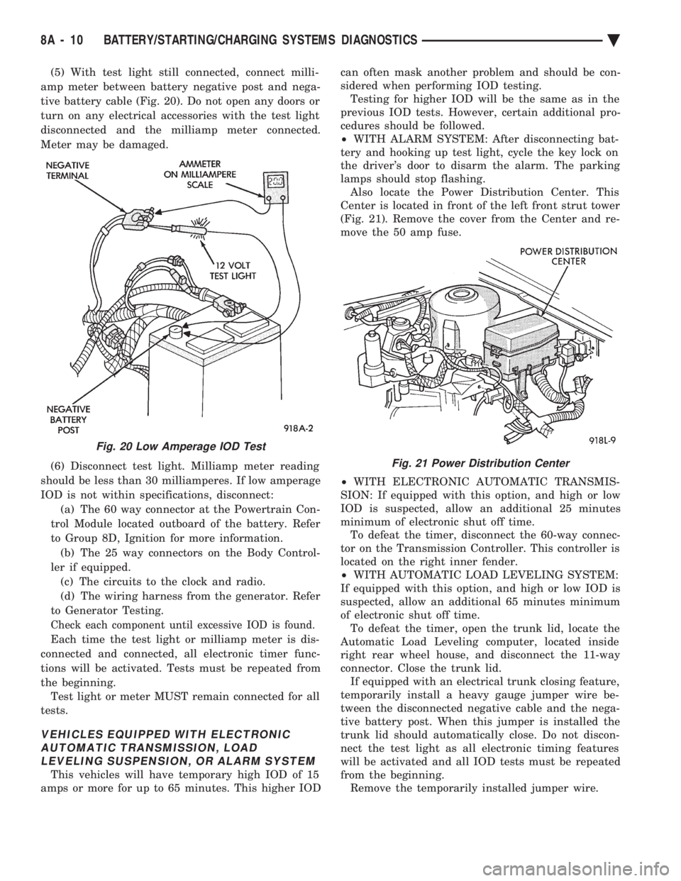
(5) With test light still connected, connect milli-
amp meter between battery negative post and nega-
tive battery cable (Fig. 20). Do not open any doors or
turn on any electrical accessories with the test light
disconnected and the milliamp meter connected.
Meter may be damaged.
(6) Disconnect test light. Milliamp meter reading
should be less than 30 milliamperes. If low amperage
IOD is not within specifications, disconnect: (a) The 60 way connector at the Powertrain Con-
trol Module located outboard of the battery. Refer
to Group 8D, Ignition for more information. (b) The 25 way connectors on the Body Control-
ler if equipped. (c) The circuits to the clock and radio.
(d) The wiring harness from the generator. Refer
to Generator Testing.
Check each component until excessive IOD is found.
Each time the test light or milliamp meter is dis-
connected and connected, all electronic timer func-
tions will be activated. Tests must be repeated from
the beginning. Test light or meter MUST remain connected for all
tests.
VEHICLES EQUIPPED WITH ELECTRONIC AUTOMATIC TRANSMISSION, LOADLEVELING SUSPENSION, OR ALARM SYSTEM
This vehicles will have temporary high IOD of 15
amps or more for up to 65 minutes. This higher IOD can often mask another problem and should be con-
sidered when performing IOD testing. Testing for higher IOD will be the same as in the
previous IOD tests. However, certain additional pro-
cedures should be followed.
² WITH ALARM SYSTEM: After disconnecting bat-
tery and hooking up test light, cycle the key lock on
the driver's door to disarm the alarm. The parking
lamps should stop flashing. Also locate the Power Distribution Center. This
Center is located in front of the left front strut tower
(Fig. 21). Remove the cover from the Center and re-
move the 50 amp fuse.
² WITH ELECTRONIC AUTOMATIC TRANSMIS-
SION: If equipped with this option, and high or low
IOD is suspected, allow an additional 25 minutes
minimum of electronic shut off time. To defeat the timer, disconnect the 60-way connec-
tor on the Transmission Controller. This controller is
located on the right inner fender.
² WITH AUTOMATIC LOAD LEVELING SYSTEM:
If equipped with this option, and high or low IOD is
suspected, allow an additional 65 minutes minimum
of electronic shut off time. To defeat the timer, open the trunk lid, locate the
Automatic Load Leveling computer, located inside
right rear wheel house, and disconnect the 11-way
connector. Close the trunk lid. If equipped with an electrical trunk closing feature,
temporarily install a heavy gauge jumper wire be-
tween the disconnected negative cable and the nega-
tive battery post. When this jumper is installed the
trunk lid should automatically close. Do not discon-
nect the test light as all electronic timing features
will be activated and all IOD tests must be repeated
from the beginning. Remove the temporarily installed jumper wire.
Fig. 20 Low Amperage IOD Test
Fig. 21 Power Distribution Center
8A - 10 BATTERY/STARTING/CHARGING SYSTEMS DIAGNOSTICS Ä
Page 610 of 2438
meter should show continuity. If no continuity per-
form the following test. Continuity OK, go to step 12.(a) Using an ohmmeter test continuity between
pin 29 of powertrain control module and pin 3 of
the stop lamp switch connector. (b) If no continuity, repair as necessary.
(c) If continuity, refer to Stop Lamp Switch Test.
(d) If stop lamp switch test OK, Test continuity
between pin 6 of stop lamp switch and ground.
(14) Using an ohmmeter, touch one lead to a good
body ground and touch the other lead to pin 30. The
meter should show no continuity when transmission
is in DRIVE and continuity when in PARK or NEU-
TRAL. If not test Neutral Start and Back-Up switch
using DRB II.
VEHICLE SPEED CONTROL SWITCH TEST
WARNING: IF REMOVAL OF AIR BAG MODULE IS
NECESSARY, REFER TO GROUP 8M, RESTRAINT
SYSTEMS.
(1) Remove the switch and disconnect 4-way con-
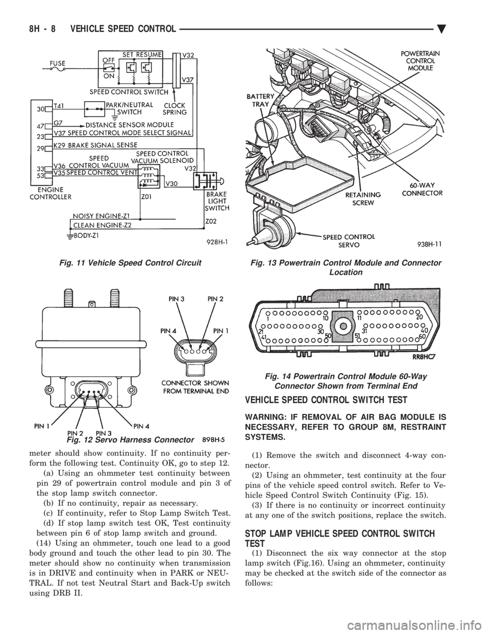
nector. (2) Using an ohmmeter, test continuity at the four
pins of the vehicle speed control switch. Refer to Ve-
hicle Speed Control Switch Continuity (Fig. 15). (3) If there is no continuity or incorrect continuity
at any one of the switch positions, replace the switch.
STOP LAMP VEHICLE SPEED CONTROL SWITCH
TEST
(1) Disconnect the six way connector at the stop
lamp switch (Fig.16). Using an ohmmeter, continuity
may be checked at the switch side of the connector as
follows:
Fig. 11 Vehicle Speed Control Circuit
Fig. 12 Servo Harness Connector
Fig. 13 Powertrain Control Module and Connector Location
Fig. 14 Powertrain Control Module 60-WayConnector Shown from Terminal End
8H - 8 VEHICLE SPEED CONTROL Ä
Page 611 of 2438
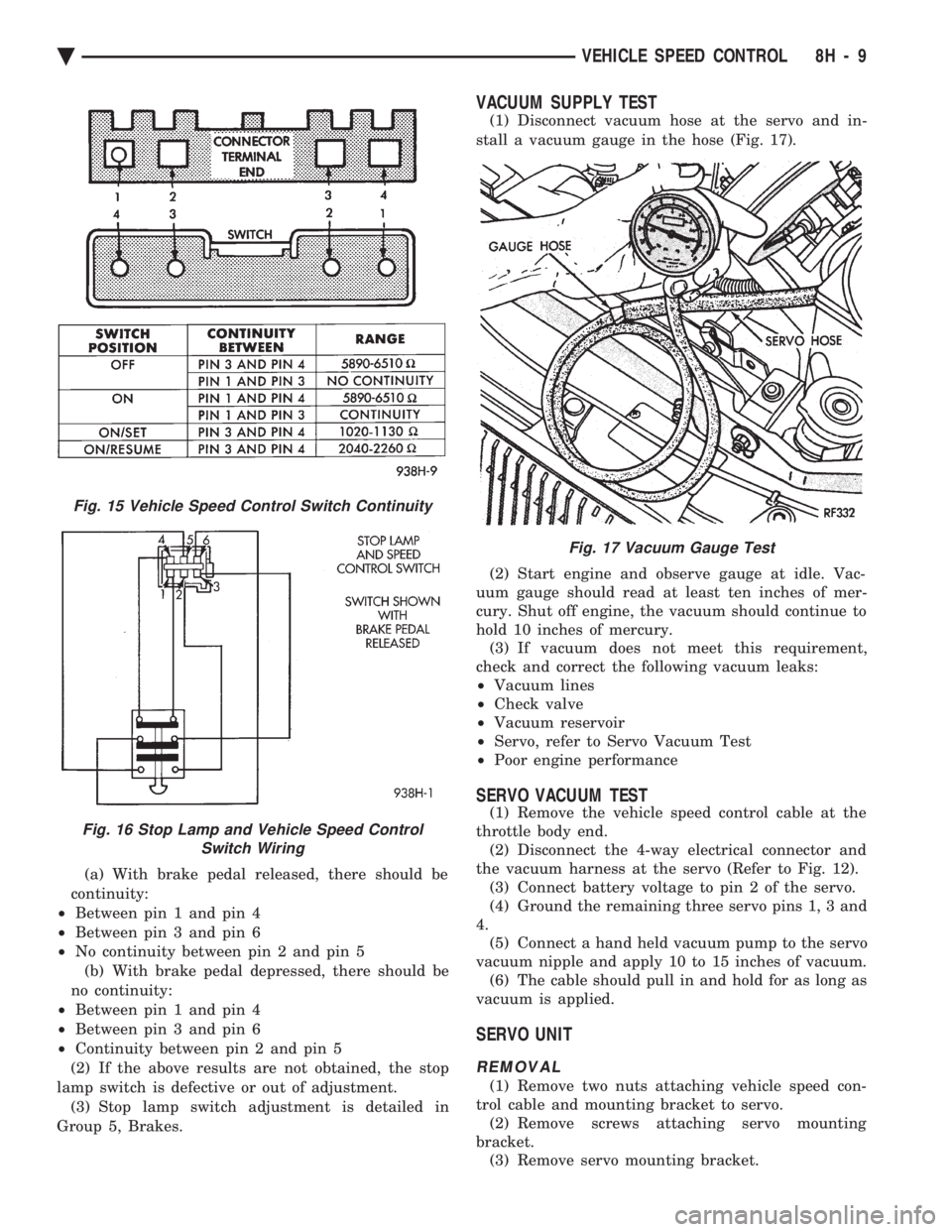
(a) With brake pedal released, there should be
continuity:
² Between pin 1 and pin 4
² Between pin 3 and pin 6
² No continuity between pin 2 and pin 5
(b) With brake pedal depressed, there should be
no continuity:
² Between pin 1 and pin 4
² Between pin 3 and pin 6
² Continuity between pin 2 and pin 5
(2) If the above results are not obtained, the stop
lamp switch is defective or out of adjustment. (3) Stop lamp switch adjustment is detailed in
Group 5, Brakes.
VACUUM SUPPLY TEST
(1) Disconnect vacuum hose at the servo and in-
stall a vacuum gauge in the hose (Fig. 17).
(2) Start engine and observe gauge at idle. Vac-
uum gauge should read at least ten inches of mer-
cury. Shut off engine, the vacuum should continue to
hold 10 inches of mercury. (3) If vacuum does not meet this requirement,
check and correct the following vacuum leaks:
² Vacuum lines
² Check valve
² Vacuum reservoir
² Servo, refer to Servo Vacuum Test
² Poor engine performance
SERVO VACUUM TEST
(1) Remove the vehicle speed control cable at the
throttle body end. (2) Disconnect the 4-way electrical connector and
the vacuum harness at the servo (Refer to Fig. 12). (3) Connect battery voltage to pin 2 of the servo.
(4) Ground the remaining three servo pins 1, 3 and
4. (5) Connect a hand held vacuum pump to the servo
vacuum nipple and apply 10 to 15 inches of vacuum. (6) The cable should pull in and hold for as long as
vacuum is applied.
SERVO UNIT
REMOVAL
(1) Remove two nuts attaching vehicle speed con-
trol cable and mounting bracket to servo. (2) Remove screws attaching servo mounting
bracket. (3) Remove servo mounting bracket.
Fig. 15 Vehicle Speed Control Switch Continuity
Fig. 16 Stop Lamp and Vehicle Speed Control Switch Wiring
Fig. 17 Vacuum Gauge Test
Ä VEHICLE SPEED CONTROL 8H - 9
Page 633 of 2438
CONDITION: WIPERS START TO WIPE, BUT STOP BEFORE ONE COMPLETE CYCLE ANDDO NOT RETURN TO PARK POSITION
PROCEDURE
(1) Verify that motor will park when the column
switch is put in the OFF position. (2) Set wiper control switch to maximum DELAY
and allow motor to run until it stops during the wipe
cycle. When motor stops, disconnect 25-way blue con-
nector from the body controller. (3) Connect positive lead of voltmeter to pin 20 of
blue connector and negative lead to the metal case of
the body controller. (a) If voltmeter reads 0, check wiring for an open
circuit. (b) If voltmeter reads 10 to 15 volts, proceed to
step 4.
(4) Using an ohmmeter or continuity tester; (a) Check for continuity between pins 20 and 24
of blue connector of the body controller. (b) Reverse ohmmeter leads on pins 20 and 24,
again checking for continuity. (c) If continuity between pins 20 and 24 is not
observed in both steps a and b, replace the body
controller.
CONDITION: EXCESSIVE DELAY OF MORE THAN 30 SECONDS OR INADEQUATEVARIATION IN DELAY
PROCEDURE
(1) Variations in delay should be as follows: (a) Minimum delay control to extreme counter-
clockwise position before first detent of 1/2 to 2 sec-
onds. (b) Maximum delay control to extreme clockwise
position before OFF detent of 15 to 25 seconds.
(2) If there is excessive delay or no variations in
delay, remove the wiper motor wiring harness while
the motor is parked in the OFF position. (3) Remove 25-way blue connector from the body
controller. (4) Set wiper control switch to maximum DELAY
position. (5) With ignition switch in ON position, measure
voltage between pin 9 of black connector and a good
ground. (a) If voltmeter reads 0, proceed to step 6.
(b) If voltmeter reads 10 to 15 volts, proceed to
step 7.
(6) Set wiper control switch to minimum DELAY
position and measure voltage between pin 9 of blue
connector and a good ground. If voltmeter reads 0,
check for an open circuit in the intermittent wipe
wiring harness. (7) Remove wiper motor circuit fuse. (8) Using an ohmmeter, measure the resistance be-
tween pins 9 and 22 of the body controller 25-way
black connector. Set the wiper control switch first to
minimum DELAY and then maximum DELAY. (a) If resistance reading at minimum DELAY
setting is between 0 and 15 ohms, and at maxi-
mum DELAY setting the resistance is between
240,000 and 400,000 ohms, replace the body con-
troller. (b) If the resistance values above are not ob-
tained, replace the wiper control switch.
CONDITION: WIPERS DO NOT RUN CONTINUALLY WHEN WASH CONTROL ISOPERATED DURING DELAY MODE
PROCEDURE
(1) Disconnect 25-way blue connector from the
body controller (2) Using a voltmeter, connect the positive lead to
pin 10 of the (Black) connector. Connect negative
lead to the body computer metal case. (3) Set wiper control switch to DELAY position.
(4) Depress wash switch.
(5) If voltage reads 0, check switch relay and wir-
ing. (6) If voltage is between 10 and 15 volts, the prob-
lem is in the body controller.
CONDITION: IN DELAY MODE, WIPERS RUN CONTINUALLY WHEN WASH IS OPERATEDBUT DO NOT PROVIDE FOUR EXTRA WIPESWHEN WASH CONTROL IS RELEASED
PROCEDURE
Replace body controller.
CONDITION: WIPERS START ERRATICALLY DURING DELAY MODE
PROCEDURE
(1) Verify that the ground connection at the in-
strument panel is making a good connection, free
from paint and is tight. (2) Verify that the motor ground strap is making
good contact and that the motor mounting bolts are
tight. (3) Verify that the wiring connections to the body
controller, wiper motor, and wiper motor switch are
tight and free of corrosion. (4) If condition is not corrected, problem is with
the body controller
Ä WINDSHIELD WIPER AND WASHER SYSTEMS 8K - 13
Page 637 of 2438
WINDSHIELD WASHERS INDEX
page page
General Information ....................... 17
Washer Nozzle .......................... 19 Washer Reservoir Pump
................... 18
Washer Reservoirs ....................... 17
GENERAL INFORMATION
All models are equipped with electric operated
windshield washer pumps. The wash function can be accessed in the OFF po-
sition of the wiper control switch. Holding the wash
button depressed when the switch is in the OFF po-
sition will operate the wipers and washer motor
pump continuously until the washer button is re-
leased. Releasing the button will stop the washer
pump but the wipers will complete the current wipe
cycle. Then followed by an average of two more wipe
cycles ( 61) before the wipers park and the module
turns off. Whenever a windshield washer malfunction occurs,
first verify that the windshield washer wire harness
is properly connected to all connectors before starting
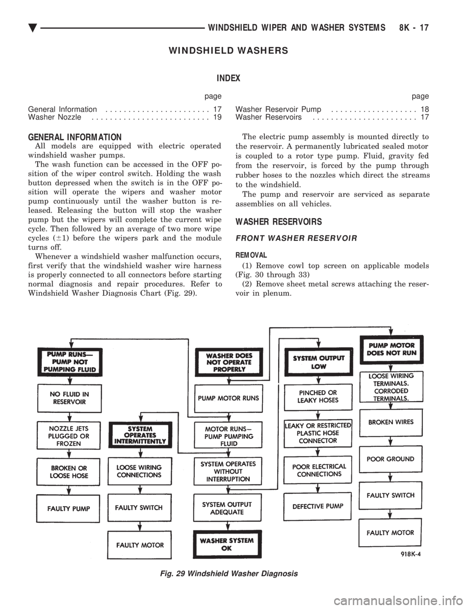
normal diagnosis and repair procedures. Refer to
Windshield Washer Diagnosis Chart (Fig. 29). The electric pump assembly is mounted directly to
the reservoir. A permanently lubricated sealed motor
is coupled to a rotor type pump. Fluid, gravity fed
from the reservoir, is forced by the pump through
rubber hoses to the nozzles which direct the streams
to the windshield. The pump and reservoir are serviced as separate
assemblies on all vehicles.
WASHER RESERVOIRS
FRONT WASHER RESERVOIR
REMOVAL
(1) Remove cowl top screen on applicable models
(Fig. 30 through 33) (2) Remove sheet metal screws attaching the reser-
voir in plenum.
Fig. 29 Windshield Washer Diagnosis
Ä WINDSHIELD WIPER AND WASHER SYSTEMS 8K - 17
Page 703 of 2438
VEHICLE THEFT SECURITY SYSTEM
CONTENTS
page page
GENERAL INFORMATION .................. 1
SECURITY SYSTEM DOOR SWITCH REPLACEMENT ........................ 2
SECURITY SYSTEM HOOD SWITCH REPLACEMENT ........................ 2 SYSTEM SELF-TESTS
.................... 1
VEHICLE THEFT SECURITY SYSTEM MODULE REPLACEMENT ........................ 2
WHAT WILL TRIGGER THE SYSTEM ........ 1
GENERAL INFORMATION
JUMP-STARTING, VEHICLE EQUIPPED
WITH THEFT SECURITY SYSTEM . After the
booster battery has been connected, the Theft System
must be turned OFF. Using the key, lock then un-
lock either front door. This turns the Theft System
OFF and the remainder of the Jump-Starting proce-
dure can be followed. If this procedure is not followed, the Theft System
electronics will prevent the engine from starting. If a new Powertrain Control Module is installed,
the engine has to be cranked 20 times before the
alarm system activated. This passive system is designed to protect against
whole vehicle theft. The system monitors vehicle
doors, hood, trunk key cylinder, and ignition action
for unauthorized operation. The alarm activates by
sounding the horn, flashing the park and tail lamps,
and providing an engine kill feature (Fig. 1). Passive arming occurs upon normal vehicle exit,
open door, lock with power locks, close door. The SET
lamp in the panel will flash for 15 seconds, indicat-
ing that arming is in progress. If no monitored sys-
tems are activated during this period, the system
will arm. If the hood or trunk key cylinder switches
are not sensed by the system. The SET lamp will re-
main lit during the arming process, although the sys-
tem will still arm. The system is to be considered as
an active armed system when using the Remote Key-
less Entry. If the SET lamp does not illuminate at all
upon door closing it indicates that the system is not
arming. Passive disarming occurs upon normal vehicle en-
try unlocking either door with the key, or unlocking
using the Remote Keyless transmitter. This disarm-
ing will also halt the alarm once it has been acti-
vated. Whenever the battery is disconnected and recon-
nected, the Vehicle Theft Security System enters
power up alarm mode which flashes the park and tail
lamps and prevents the engine from running. To exit
this mode, the system must be disarmed as men-
tioned above. A tamper alert exists to notify the driver that the
alarm had been activated, and the alarm has since
timed-out for more than 18 minutes. This alert con-
sists of 3 horn pulses when the vehicle is disarmed. The alarm system will not arm if the doors are
manually locked, providing a manual override of the
alarm.
WHAT WILL TRIGGER THE SYSTEM
One of the following actions will trigger the system
while it is armed. Without properly disarming sys-
tem, by using the key or the remote transmitter. (1) Opening the HOOD.
(2) Opening any DOOR.
(3) Removing the TRUNK KEY CYLINDER.
(4) Turning the IGNITION ON.
(5) The ignition switch can be turned to the acces-
sory position without triggering alarm system.
SYSTEM SELF-TESTS
A diagnostics mode is available in the system to
verify operation of all monitored switches or circuits.
To enter diagnostics, cycle the ignition key to the ac-
cessory position 3 times, leaving the key in this po-
sition. Upon entering diagnostics, the park and tail lamps
will begin flashing to verify their operation. In addi-
tion, the horn will sound twice to indicate that the
trunk key cylinder is in its proper position. Return-
ing the ignition to the OFF position will stop the
lamps from flashing while keeping the system in di-
agnostics. While in diagnostics mode, a horn pulse should oc-
cur at each of the following events indicating proper
operation: (1) Beginning with all doors closed, open then close
each door. The horn will sound when the door ajar
switch closes, and then again when the switch opens.
There must b e a 1 second delay between closing and
opening the switch. (2) Open, then close the hood. The horn will sound
when the hood is opened, and again when it is closed.
Ä VEHICLE THEFT SECURITY SYSTEM 8Q - 1
Page 931 of 2438
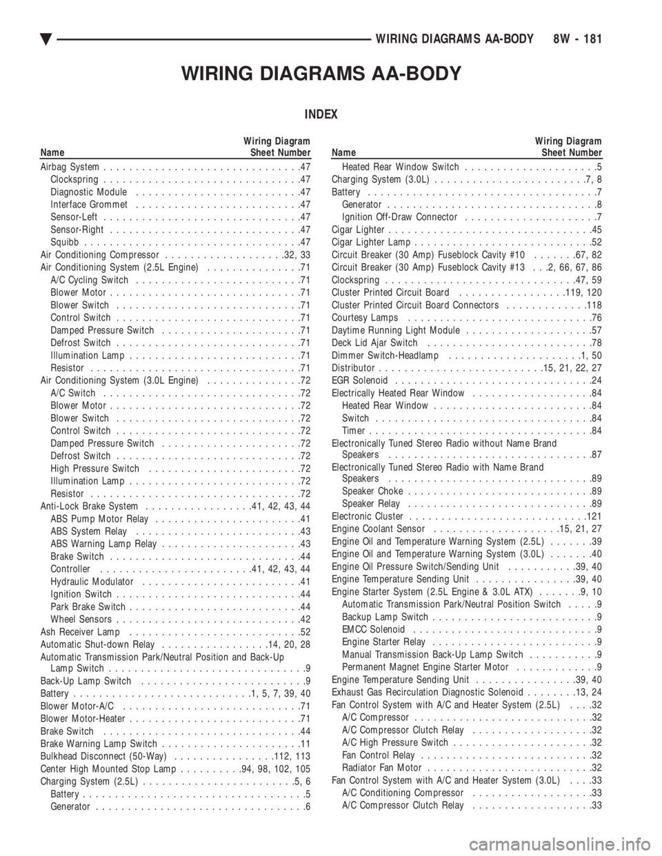
WIRING DIAGRAMS AA-BODY
INDEX
Wiring Diagram
Name Sheet Number
Airbag System ...............................47
Clockspring ...............................47
Diagnostic Module ..........................47
Interface Grommet ..........................47
Sensor-Left ...............................47
Sensor-Right ..............................47
Squibb ..................................47
Air Conditioning Compressor ...................32, 33
Air Conditioning System (2.5L Engine) ...............71
A/C Cycling Switch ..........................71
Blower Motor ..............................71
Blower Switch .............................71
Control Switch .............................71
Damped Pressure Switch ......................71
Defrost Switch .............................71
Illumination Lamp ...........................71
Resistor .................................71
Air Conditioning System (3.0L Engine) ...............72
A/C Switch ...............................72
Blower Motor ..............................72
Blower Switch .............................72
Control Switch .............................72
Damped Pressure Switch ......................72
Defrost Switch .............................72
High Pressure Switch ........................72
Illumination Lamp ...........................72
Resistor .................................72
Anti-Lock Brake System .................41, 42, 43, 44
ABS Pump Motor Relay .......................41
ABS System Relay ..........................43
ABS Warning Lamp Relay ......................43
Brake Switch ..............................44
Controller ....................... .41, 42, 43, 44
Hydraulic Modulator .........................41
Ignition Switch .............................44
Park Brake Switch ...........................44
Wheel Sensors .............................42
Ash Receiver Lamp ...........................52
Automatic Shut-down Relay .................14, 20, 28
Automatic Transmission Park/Neutral Position and Back-Up Lamp Switch ...............................9
Back-Up Lamp Switch ..........................9
Battery ............................1,5,7,39,40
Blower Motor-A/C ............................71
Blower Motor-Heater ...........................71
Brake Switch ...............................44
Brake Warning Lamp Switch ......................11
Bulkhead Disconnect (50-Way) ................112, 113
Center High Mounted Stop Lamp ..........94, 98, 102, 105
Charging System (2.5L) ........................5,6
Battery ...................................5
Generator .................................6Wiring Diagram
Name Sheet Number
Heated Rear Window Switch .....................5
Charging System (3.0L) ........................7,8
Battery ....................................7
Generator .................................8
Ignition Off-Draw Connector .....................7
Cigar Lighter ................................45
Cigar Lighter Lamp ............................52
Circuit Breaker (30 Amp) Fuseblock Cavity #10 .......67, 82
Circuit Breaker (30 Amp) Fuseblock Cavity #13 . . .2, 66, 67, 86
Clockspring ............................. .47, 59
Cluster Printed Circuit Board .................119, 120
Cluster Printed Circuit Board Connectors .............118
Courtesy Lamps .............................76
Daytime Running Light Module ....................57
Deck Lid Ajar Switch ..........................78
Dimmer Switch-Headlamp .....................1,50
Distributor ......................... .15, 21, 22, 27
EGR Solenoid ...............................24
Electrically Heated Rear Window ...................84
Heated Rear Window .........................84
Switch ..................................84
Timer ...................................84
Electronically Tuned Stereo Radio without Name Brand Speakers ................................87
Electronically Tuned Stereo Radio with Name Brand Speakers ................................89
Speaker Choke .............................89
Speaker Relay .............................89
Electronic Cluster ........................... .121
Engine Coolant Sensor ................... .15, 21, 27
Engine Oil and Temperature Warning System (2.5L) .......39
Engine Oil and Temperature Warning System (3.0L) .......40
Engine Oil Pressure Switch/Sending Unit ...........39, 40
Engine Temperature Sending Unit ................39, 40
Engine Starter System (2.5L Engine & 3.0L ATX) .......9,10
Automatic Transmission Park/Neutral Position Switch .....9
Backup Lamp Switch ..........................9
EMCC Solenoid .............................9
Engine Starter Relay ..........................9
Manual Transmission Back-Up Lamp Switch ...........9
Permanent Magnet Engine Starter Motor .............9
Engine Temperature Sending Unit ................39, 40
Exhaust Gas Recirculation Diagnostic Solenoid ........13, 24
Fan Control System with A/C and Heater System (2.5L) ....32
A/C Compressor ............................32
A/C Compressor Clutch Relay ...................32
A/C High Pressure Switch ......................32
Fan Control Relay ...........................32
Radiator Fan Motor ..........................32
Fan Control System with A/C and Heater System (3.0L) ....33
A/C Conditioning Compressor ...................33
A/C Compressor Clutch Relay ...................33
Ä WIRING DIAGRAMS AA-BODY 8W - 181
Page 933 of 2438
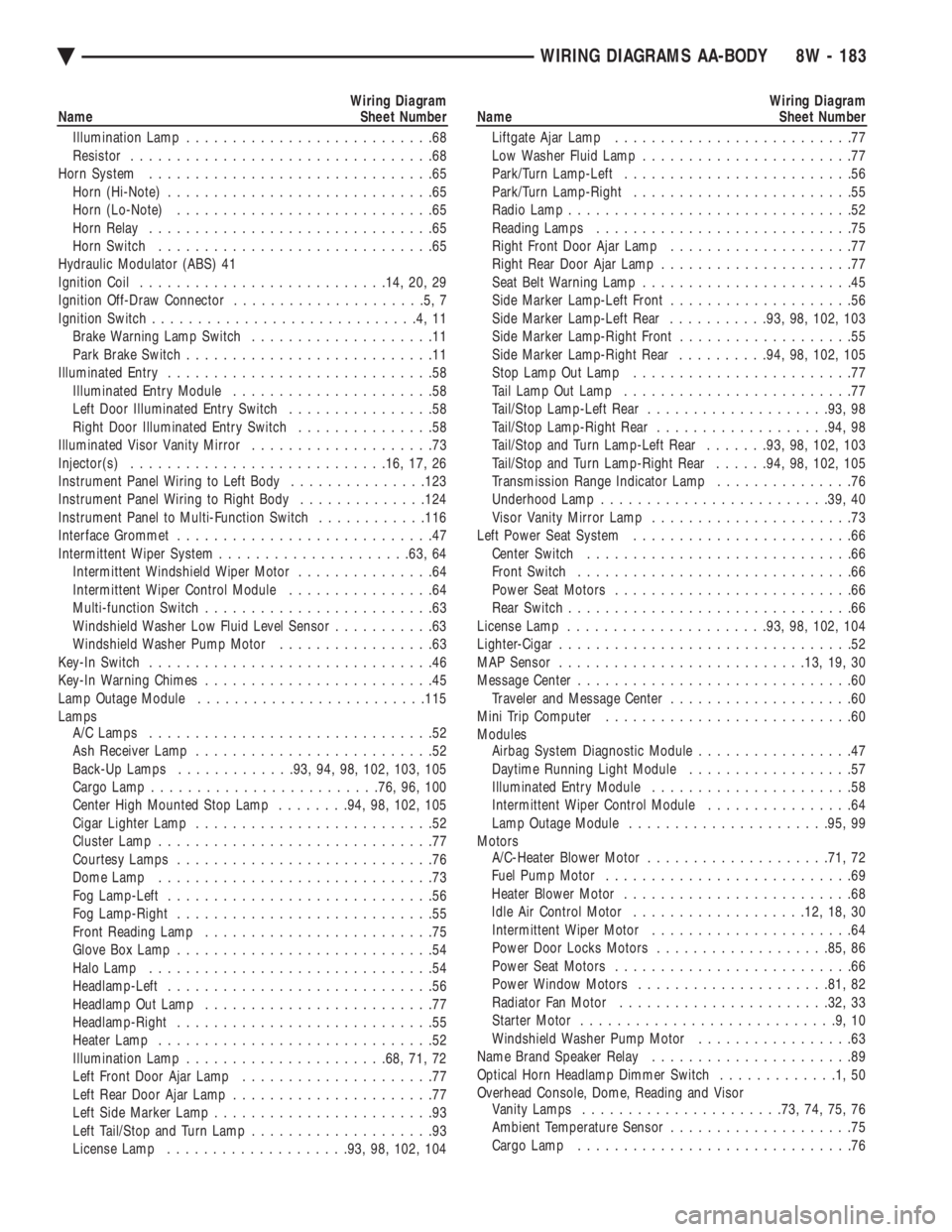
Wiring Diagram
Name Sheet Number
Illumination Lamp ...........................68
Resistor .................................68
Horn System ...............................65
Horn (Hi-Note) .............................65
Horn (Lo-Note) ............................65
Horn Relay ...............................65
Horn Switch ..............................65
Hydraulic Modulator (ABS) 41
Ignition Coil .......................... .14, 20, 29
Ignition Off-Draw Connector .....................5,7
Ignition Switch .............................4,11
Brake Warning Lamp Switch ....................11
Park Brake Switch ...........................11
Illuminated Entry .............................58
Illuminated Entry Module ......................58
Left Door Illuminated Entry Switch ................58
Right Door Illuminated Entry Switch ...............58
Illuminated Visor Vanity Mirror ....................73
Injector(s) ........................... .16, 17, 26
Instrument Panel Wiring to Left Body ...............123
Instrument Panel Wiring to Right Body ..............124
Instrument Panel to Multi-Function Switch ............116
Interface Grommet ............................47
Intermittent Wiper System .................... .63, 64
Intermittent Windshield Wiper Motor ...............64
Intermittent Wiper Control Module ................64
Multi-function Switch .........................63
Windshield Washer Low Fluid Level Sensor ...........63
Windshield Washer Pump Motor .................63
Key-In Switch ...............................46
Key-In Warning Chimes .........................45
Lamp Outage Module ........................ .115
Lamps A/C Lamps ...............................52
Ash Receiver Lamp ..........................52
Back-Up Lamps ............ .93, 94, 98, 102, 103, 105
Cargo Lamp ........................ .76, 96, 100
Center High Mounted Stop Lamp ........94, 98, 102, 105
Cigar Lighter Lamp ..........................52
Cluster Lamp ..............................77
Courtesy Lamps ............................76
Dome Lamp ..............................73
Fog Lamp-Left .............................56
Fog Lamp-Right ............................55
Front Reading Lamp .........................75
Glove Box Lamp ............................54
Halo Lamp ...............................54
Headlamp-Left .............................56
Headlamp Out Lamp .........................77
Headlamp-Right ............................55
Heater Lamp ..............................52
Illumination Lamp ..................... .68, 71, 72
Left Front Door Ajar Lamp .....................77
Left Rear Door Ajar Lamp ......................77
Left Side Marker Lamp ........................93
Left Tail/Stop and Turn Lamp ....................93
License Lamp ................... .93, 98, 102, 104Wiring Diagram
Name Sheet Number
Liftgate Ajar Lamp ..........................77
Low Washer Fluid Lamp .......................77
Park/Turn Lamp-Left .........................56
Park/Turn Lamp-Right ........................55
Radio Lamp ...............................52
Reading Lamps ............................75
Right Front Door Ajar Lamp ....................77
Right Rear Door Ajar Lamp .....................77
Seat Belt Warning Lamp .......................45
Side Marker Lamp-Left Front ....................56
Side Marker Lamp-Left Rear ...........93, 98, 102, 103
Side Marker Lamp-Right Front ...................55
Side Marker Lamp-Right Rear ..........94, 98, 102, 105
Stop Lamp Out Lamp ........................77
Tail Lamp Out Lamp .........................77
Tail/Stop Lamp-Left Rear ................... .93, 98
Tail/Stop Lamp-Right Rear .................. .94, 98
Tail/Stop and Turn Lamp-Left Rear .......93, 98, 102, 103
Tail/Stop and Turn Lamp-Right Rear ......94, 98, 102, 105
Transmission Range Indicator Lamp ...............76
Underhood Lamp ........................ .39, 40
Visor Vanity Mirror Lamp ......................73
Left Power Seat System ........................66
Center Switch .............................66
Front Switch ..............................66
Power Seat Motors ..........................66
Rear Switch ...............................66
License Lamp ..................... .93, 98, 102, 104
Lighter-Cigar ................................52
MAP Sensor .......................... .13, 19, 30
Message Center ..............................60
Traveler and Message Center ....................60
Mini Trip Computer ...........................60
Modules Airbag System Diagnostic Module .................47
Daytime Running Light Module ..................57
Illuminated Entry Module ......................58
Intermittent Wiper Control Module ................64
Lamp Outage Module ..................... .95, 99
Motors A/C-Heater Blower Motor ................... .71, 72
Fuel Pump Motor ...........................69
Heater Blower Motor .........................68
Idle Air Control Motor .................. .12, 18, 30
Intermittent Wiper Motor ......................64
Power Door Locks Motors .................. .85, 86
Power Seat Motors ..........................66
Power Window Motors .................... .81, 82
Radiator Fan Motor ...................... .32, 33
Starter Motor ............................9,10
Windshield Washer Pump Motor .................63
Name Brand Speaker Relay ......................89
Optical Horn Headlamp Dimmer Switch .............1,50
Overhead Console, Dome, Reading and Visor Vanity Lamps ..................... .73, 74, 75, 76
Ambient Temperature Sensor ....................75
Cargo Lamp ..............................76
Ä WIRING DIAGRAMS AA-BODY 8W - 183