ABS CHEVROLET DYNASTY 1993 Owner's Manual
[x] Cancel search | Manufacturer: CHEVROLET, Model Year: 1993, Model line: DYNASTY, Model: CHEVROLET DYNASTY 1993Pages: 2438, PDF Size: 74.98 MB
Page 118 of 2438
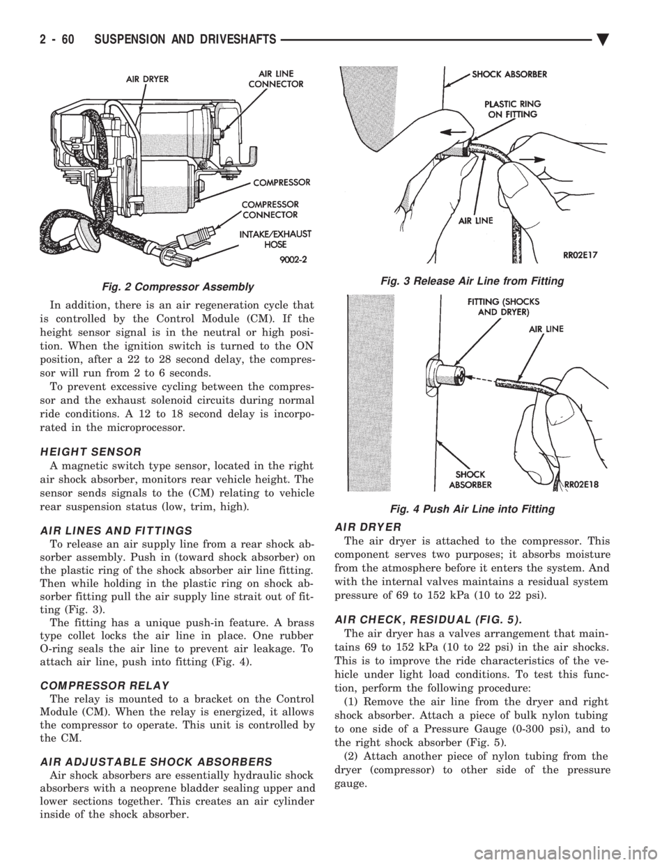
In addition, there is an air regeneration cycle that
is controlled by the Control Module (CM). If the
height sensor signal is in the neutral or high posi-
tion. When the ignition switch is turned to the ON
position, after a 22 to 28 second delay, the compres-
sor will run from 2 to 6 seconds. To prevent excessive cycling between the compres-
sor and the exhaust solenoid circuits during normal
ride conditions. A 12 to 18 second delay is incorpo-
rated in the microprocessor.
HEIGHT SENSOR
A magnetic switch type sensor, located in the right
air shock absorber, monitors rear vehicle height. The
sensor sends signals to the (CM) relating to vehicle
rear suspension status (low, trim, high).
AIR LINES AND FITTINGS
To release an air supply line from a rear shock ab-
sorber assembly. Push in (toward shock absorber) on
the plastic ring of the shock absorber air line fitting.
Then while holding in the plastic ring on shock ab-
sorber fitting pull the air supply line strait out of fit-
ting (Fig. 3). The fitting has a unique push-in feature. A brass
type collet locks the air line in place. One rubber
O-ring seals the air line to prevent air leakage. To
attach air line, push into fitting (Fig. 4).
COMPRESSOR RELAY
The relay is mounted to a bracket on the Control
Module (CM). When the relay is energized, it allows
the compressor to operate. This unit is controlled by
the CM.
AIR ADJUSTABLE SHOCK ABSORBERS
Air shock absorbers are essentially hydraulic shock
absorbers with a neoprene bladder sealing upper and
lower sections together. This creates an air cylinder
inside of the shock absorber.
AIR DRYER
The air dryer is attached to the compressor. This
component serves two purposes; it absorbs moisture
from the atmosphere before it enters the system. And
with the internal valves maintains a residual system
pressure of 69 to 152 kPa (10 to 22 psi).
AIR CHECK, RESIDUAL (FIG. 5).
The air dryer has a valves arrangement that main-
tains 69 to 152 kPa (10 to 22 psi) in the air shocks.
This is to improve the ride characteristics of the ve-
hicle under light load conditions. To test this func-
tion, perform the following procedure: (1) Remove the air line from the dryer and right
shock absorber. Attach a piece of bulk nylon tubing
to one side of a Pressure Gauge (0-300 psi), and to
the right shock absorber (Fig. 5). (2) Attach another piece of nylon tubing from the
dryer (compressor) to other side of the pressure
gauge.
Fig. 2 Compressor AssemblyFig. 3 Release Air Line from Fitting
Fig. 4 Push Air Line into Fitting
2 - 60 SUSPENSION AND DRIVESHAFTS Ä
Page 119 of 2438
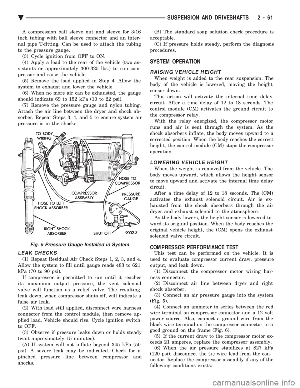
A compression ball sleeve nut and sleeve for 3/16
inch tubing with ball sleeve connector and an inter-
nal pipe T-fitting. Can be used to attach the tubing
to the pressure gauge. (3) Cycle ignition from OFF to ON.
(4) Apply a load to the rear of the vehicle (two as-
sistants or approximately 300-325 lbs.) to run com-
pressor and raise the vehicle. (5) Remove the load applied in Step 4. Allow the
system to exhaust and lower the vehicle. (6) When no more air can be exhausted, the gauge
should indicate 69 to 152 kPa (10 to 22 psi). (7) Remove the pressure gauge and nylon tubing.
Attach the air line between the dryer and shock ab-
sorber. Repeat Steps 3, 4, and 5 to ensure system air
pressure is in the shocks.
LEAK CHECKS
(1) Repeat Residual Air Check Steps 1, 2, 3, and 4.
Allow the system to fill until gauge reads 483 to 621
kPa (70 to 90 psi). If compressor is permitted to run until it reaches
its maximum output pressure, the vent solenoid
valve will function as a relief valve. The resulting
leak down, when compressor shuts off, will indicate a
false air leak. (2) With load still applied, disconnect wire harness
connector from the control module, then remove ap-
plied load. Vehicle should rise. Cycle ignition switch
to OFF. (3) Observe if pressure leaks down or holds steady
(wait approximately 15 minutes). (A) If system will not inflate beyond 345 kPa (50
psi). A severe leak may be indicated. Check for a
pinched pressure line between compressor and
shocks. (B) The standard soap solution check procedure is
acceptable. (C) If pressure holds steady, perform the diagnosis
procedures.
SYSTEM OPERATION
RAISING VEHICLE HEIGHT
When weight is added to the rear suspension. The
body of the vehicle is lowered, moving the height
sensor down. This action will activate the internal time delay
circuit. After a time delay of 12 to 18 seconds. The
control module (CM) activates the ground circuit to
the compressor relay. With the relay energized, the compressor motor
runs and air is sent through the system. As the
shock absorbers inflate, the body moves upward to a
corrected position. When the body reaches the correct
height, the control module (CM) stops the compressor
operation.
LOWERING VEHICLE HEIGHT
When the weight is removed from the vehicle. The
body moves upward, which allows the height sensor
to move upward and activate the internal time delay
circuit. After a time delay of 12 to 18 seconds. The (CM)
activates the exhaust solenoid circuit. Air is ex-
hausted from the shock absorbers through the air
dryer and exhaust solenoid to the atmosphere. As the body lowers, the height sensor is lowered to-
ward its original position. When the body reaches the
original vehicle height, the (CM) opens the exhaust
solenoid valve circuit.
COMPRESSOR PERFORMANCE TEST
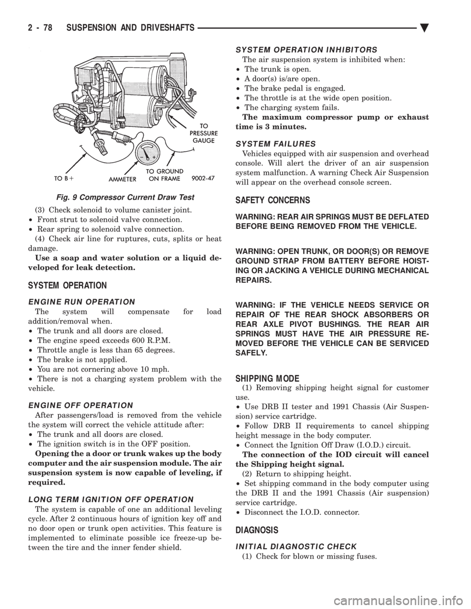
This test can be performed on the vehicle. It is
used to evaluate compressor current draw, pressure
output, and leak down. (1) Disconnect the compressor motor wiring har-
ness connector. (2) Disconnect air line between dryer and right
shock absorber. (3) Connect an air pressure gauge into the system
(Fig. 5). (4) Connect an ammeter in series between the red
wire terminal on compressor connector and a 12 volt
power source. Also, connect a ground wire from the
black wire terminal on the compressor connector to a
good ground on the frame (Fig. 6). (5) If the current draw to the compressor motor ex-
ceeds 21 amperes, replace the compressor assembly. (6) When the air pressure stabilizes at 827 kPa
(120 psi), disconnect the (+) wire lead from the con-
nector. Replace the compressor assembly if any of the
following conditions exists:
Fig. 5 Pressure Gauge Installed in System
Ä SUSPENSION AND DRIVESHAFTS 2 - 61
Page 123 of 2438
REAR LEVELING DIAGNOSTIC PROCEDURES
SELF-DIAGNOSTICS
A self-diagnostic procedure is available for the ser-
vice technician to use to detect system malfunctions.
BEFORE DIAGNOSTICS TEST
Check the 20 amp fuse (position W40) and the 30
amp circuit breaker (position W5) to be assured they
are functional components. Check all connectors that link the system into the
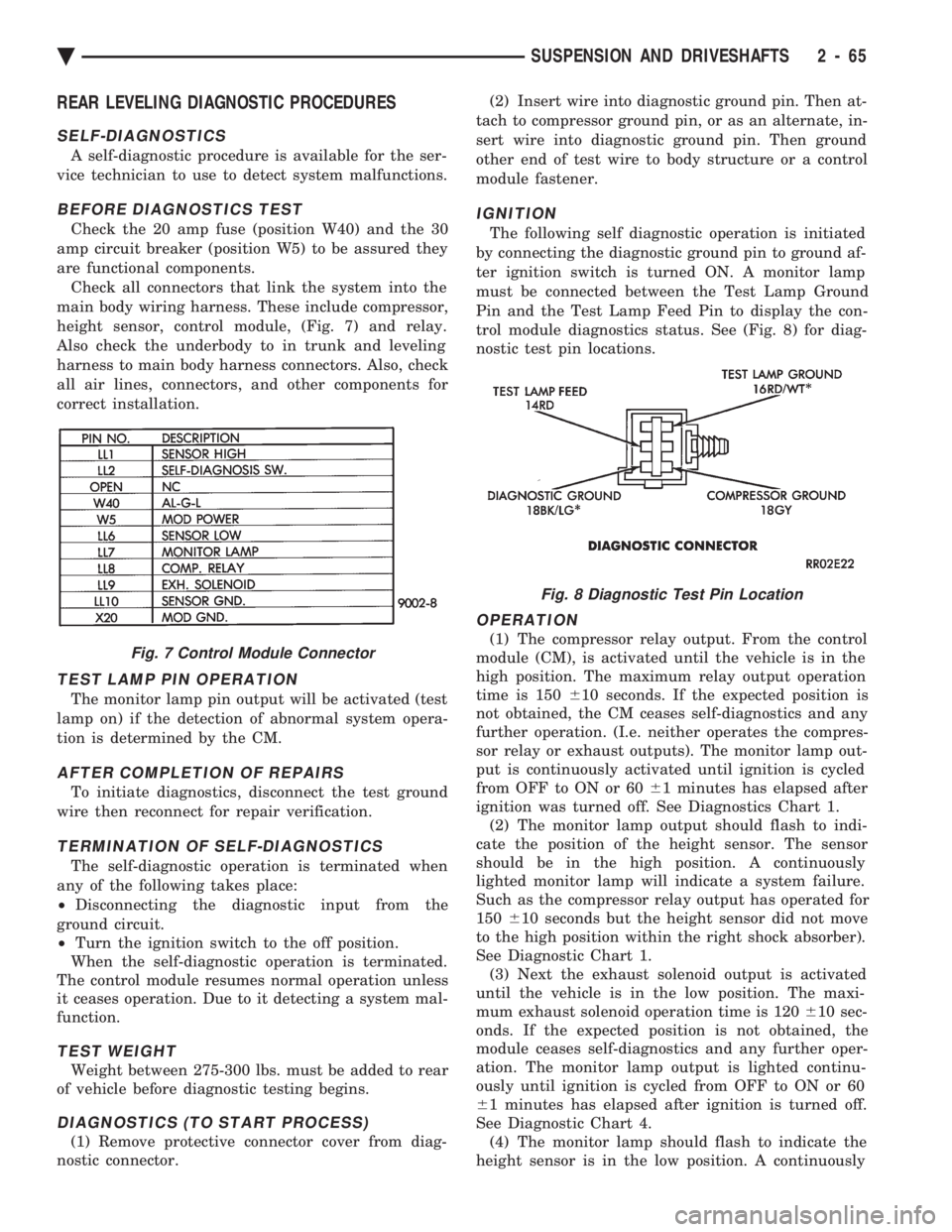
main body wiring harness. These include compressor,
height sensor, control module, (Fig. 7) and relay.
Also check the underbody to in trunk and leveling
harness to main body harness connectors. Also, check
all air lines, connectors, and other components for
correct installation.
TEST LAMP PIN OPERATION
The monitor lamp pin output will be activated (test
lamp on) if the detection of abnormal system opera-
tion is determined by the CM.
AFTER COMPLETION OF REPAIRS
To initiate diagnostics, disconnect the test ground
wire then reconnect for repair verification.
TERMINATION OF SELF-DIAGNOSTICS
The self-diagnostic operation is terminated when
any of the following takes place:
² Disconnecting the diagnostic input from the
ground circuit.
² Turn the ignition switch to the off position.
When the self-diagnostic operation is terminated.
The control module resumes normal operation unless
it ceases operation. Due to it detecting a system mal-
function.
TEST WEIGHT
Weight between 275-300 lbs. must be added to rear
of vehicle before diagnostic testing begins.
DIAGNOSTICS (TO START PROCESS)
(1) Remove protective connector cover from diag-
nostic connector. (2) Insert wire into diagnostic ground pin. Then at-
tach to compressor ground pin, or as an alternate, in-
sert wire into diagnostic ground pin. Then ground
other end of test wire to body structure or a control
module fastener.
IGNITION
The following self diagnostic operation is initiated
by connecting the diagnostic ground pin to ground af-
ter ignition switch is turned ON. A monitor lamp
must be connected between the Test Lamp Ground
Pin and the Test Lamp Feed Pin to display the con-
trol module diagnostics status. See (Fig. 8) for diag-
nostic test pin locations.
OPERATION
(1) The compressor relay output. From the control
module (CM), is activated until the vehicle is in the
high position. The maximum relay output operation
time is 150 610 seconds. If the expected position is
not obtained, the CM ceases self-diagnostics and any
further operation. (I.e. neither operates the compres-
sor relay or exhaust outputs). The monitor lamp out-
put is continuously activated until ignition is cycled
from OFF to ON or 60 61 minutes has elapsed after
ignition was turned off. See Diagnostics Chart 1. (2) The monitor lamp output should flash to indi-
cate the position of the height sensor. The sensor
should be in the high position. A continuously
lighted monitor lamp will indicate a system failure.
Such as the compressor relay output has operated for
150 610 seconds but the height sensor did not move
to the high position within the right shock absorber).
See Diagnostic Chart 1. (3) Next the exhaust solenoid output is activated
until the vehicle is in the low position. The maxi-
mum exhaust solenoid operation time is 120 610 sec-
onds. If the expected position is not obtained, the
module ceases self-diagnostics and any further oper-
ation. The monitor lamp output is lighted continu-
ously until ignition is cycled from OFF to ON or 60
6 1 minutes has elapsed after ignition is turned off.
See Diagnostic Chart 4. (4) The monitor lamp should flash to indicate the
height sensor is in the low position. A continuouslyFig. 7 Control Module Connector
Fig. 8 Diagnostic Test Pin Location
Ä SUSPENSION AND DRIVESHAFTS 2 - 65
Page 130 of 2438
CONTROL MODULE
REMOVAL
(1) Disconnect negative battery cable.
(2) Remove right side trunk trim panel.
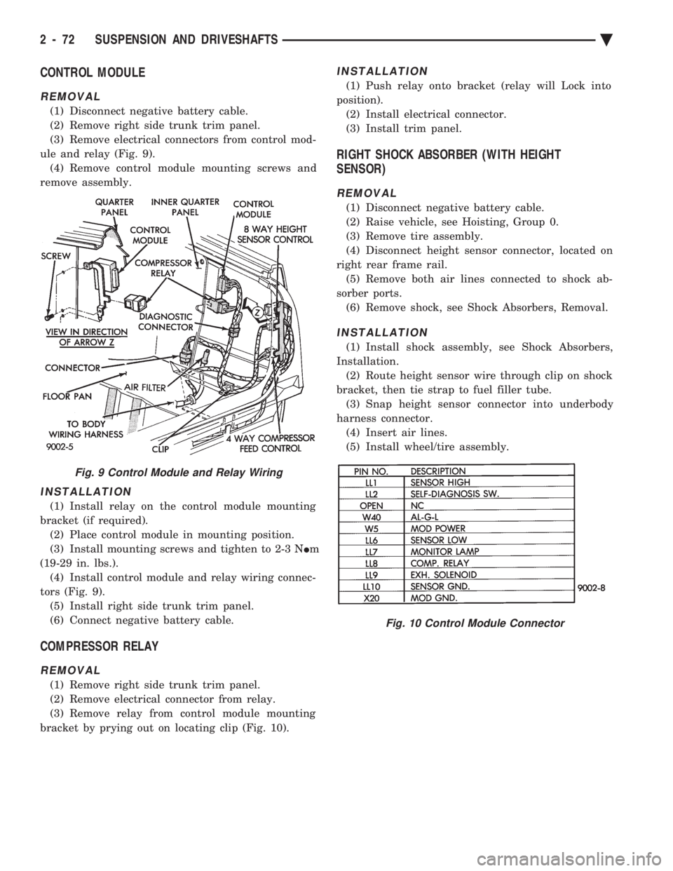
(3) Remove electrical connectors from control mod-
ule and relay (Fig. 9). (4) Remove control module mounting screws and
remove assembly.
INSTALLATION
(1) Install relay on the control module mounting
bracket (if required). (2) Place control module in mounting position.
(3) Install mounting screws and tighten to 2-3 N Im
(19-29 in. lbs.). (4) Install control module and relay wiring connec-
tors (Fig. 9). (5) Install right side trunk trim panel.
(6) Connect negative battery cable.
COMPRESSOR RELAY
REMOVAL
(1) Remove right side trunk trim panel.
(2) Remove electrical connector from relay.
(3) Remove relay from control module mounting
bracket by prying out on locating clip (Fig. 10).
INSTALLATION
(1) Push relay onto bracket (relay will Lock into
position). (2) Install electrical connector.
(3) Install trim panel.
RIGHT SHOCK ABSORBER (WITH HEIGHT
SENSOR)
REMOVAL
(1) Disconnect negative battery cable.
(2) Raise vehicle, see Hoisting, Group 0.
(3) Remove tire assembly.
(4) Disconnect height sensor connector, located on
right rear frame rail. (5) Remove both air lines connected to shock ab-
sorber ports. (6) Remove shock, see Shock Absorbers, Removal.
INSTALLATION
(1) Install shock assembly, see Shock Absorbers,
Installation. (2) Route height sensor wire through clip on shock
bracket, then tie strap to fuel filler tube. (3) Snap height sensor connector into underbody
harness connector. (4) Insert air lines.
(5) Install wheel/tire assembly.
Fig. 9 Control Module and Relay Wiring
Fig. 10 Control Module Connector
2 - 72 SUSPENSION AND DRIVESHAFTS Ä
Page 131 of 2438
AUTOMATIC AIR SUSPENSION INDEX
page page
Air Lines ............................... 75
Air Springs Rear ......................... 87
Compressor Performance Test .............. 77
Diagnosis .............................. 78
General Information ....................... 73
Recharge Air Spring ...................... 87 Right Shock Absorber (With Height Sensor)
.... 88
Safety Concerns ......................... 78
Service Procedures ....................... 85
Shipping Mode .......................... 78
Solenoids (Struts and Air Springs) ............ 86
System Operation ........................ 78
GENERAL INFORMATION
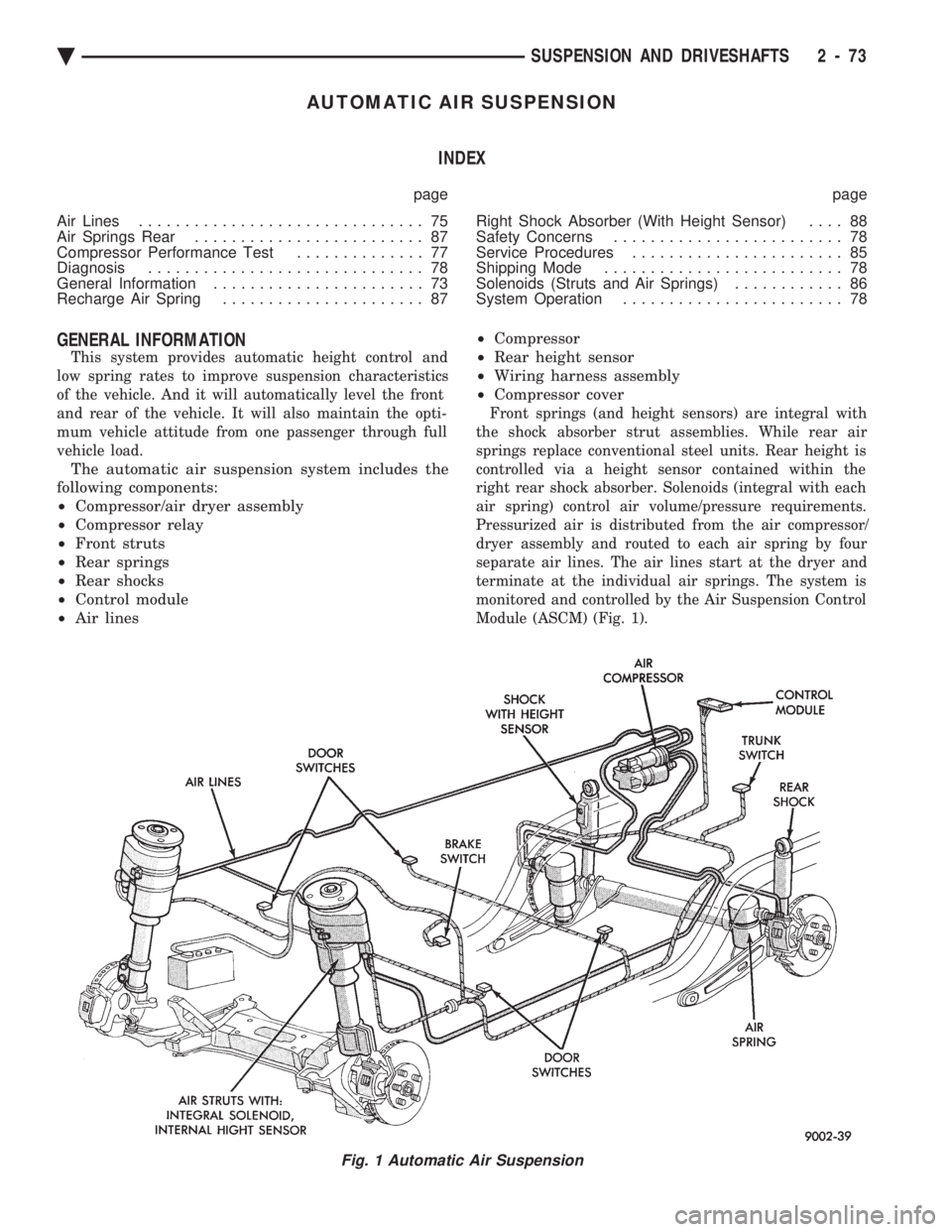
This system provides automatic height control and
low spring rates to improve suspension characteristics
of the vehicle. And it will automatically level the front
and rear of the vehicle. It will also maintain the opti-
mum vehicle attitude from one passenger through full
vehicle load.
The automatic air suspension system includes the
following components:
² Compressor/air dryer assembly
² Compressor relay
² Front struts
² Rear springs
² Rear shocks
² Control module
² Air lines ²
Compressor
² Rear height sensor
² Wiring harness assembly
² Compressor cover
Front springs (and height sensors) are integral with
the shock absorber strut assemblies. While rear air
springs replace conventional steel units. Rear height is
controlled via a height sensor contained within the
right rear shock absorber. Solenoids (integral with each
air spring) control air volume/pressure requirements.
Pressurized air is distributed from the air compressor/
dryer assembly and routed to each air spring by four
separate air lines. The air lines start at the dryer and
terminate at the individual air springs. The system is
monitored and controlled by the Air Suspension Control
Module (ASCM) (Fig. 1).
Fig. 1 Automatic Air Suspension
Ä SUSPENSION AND DRIVESHAFTS 2 - 73
Page 132 of 2438
FRONT AND REAR AIR SPRINGS
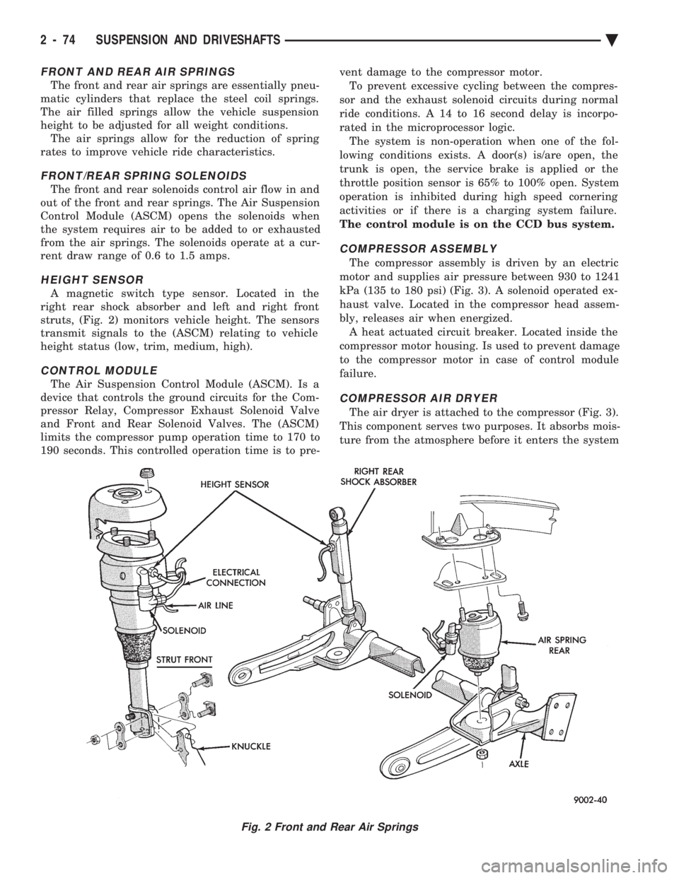
The front and rear air springs are essentially pneu-
matic cylinders that replace the steel coil springs.
The air filled springs allow the vehicle suspension
height to be adjusted for all weight conditions. The air springs allow for the reduction of spring
rates to improve vehicle ride characteristics.
FRONT/REAR SPRING SOLENOIDS
The front and rear solenoids control air flow in and
out of the front and rear springs. The Air Suspension
Control Module (ASCM) opens the solenoids when
the system requires air to be added to or exhausted
from the air springs. The solenoids operate at a cur-
rent draw range of 0.6 to 1.5 amps.
HEIGHT SENSOR
A magnetic switch type sensor. Located in the
right rear shock absorber and left and right front
struts, (Fig. 2) monitors vehicle height. The sensors
transmit signals to the (ASCM) relating to vehicle
height status (low, trim, medium, high).
CONTROL MODULE
The Air Suspension Control Module (ASCM). Is a
device that controls the ground circuits for the Com-
pressor Relay, Compressor Exhaust Solenoid Valve
and Front and Rear Solenoid Valves. The (ASCM)
limits the compressor pump operation time to 170 to
190 seconds. This controlled operation time is to pre- vent damage to the compressor motor.
To prevent excessive cycling between the compres-
sor and the exhaust solenoid circuits during normal
ride conditions. A 14 to 16 second delay is incorpo-
rated in the microprocessor logic. The system is non-operation when one of the fol-
lowing conditions exists. A door(s) is/are open, the
trunk is open, the service brake is applied or the
throttle position sensor is 65% to 100% open. System
operation is inhibited during high speed cornering
activities or if there is a charging system failure.
The control module is on the CCD bus system.
COMPRESSOR ASSEMBLY
The compressor assembly is driven by an electric
motor and supplies air pressure between 930 to 1241
kPa (135 to 180 psi) (Fig. 3). A solenoid operated ex-
haust valve. Located in the compressor head assem-
bly, releases air when energized. A heat actuated circuit breaker. Located inside the
compressor motor housing. Is used to prevent damage
to the compressor motor in case of control module
failure.
COMPRESSOR AIR DRYER
The air dryer is attached to the compressor (Fig. 3).
This component serves two purposes. It absorbs mois-
ture from the atmosphere before it enters the system
Fig. 2 Front and Rear Air Springs
2 - 74 SUSPENSION AND DRIVESHAFTS Ä
Page 136 of 2438
(3) Check solenoid to volume canister joint.
² Front strut to solenoid valve connection.
² Rear spring to solenoid valve connection.
(4) Check air line for ruptures, cuts, splits or heat
damage. Use a soap and water solution or a liquid de-
veloped for leak detection.
SYSTEM OPERATION
ENGINE RUN OPERATION
The system will compensate for load
addition/removal when.
² The trunk and all doors are closed.
² The engine speed exceeds 600 R.P.M.
² Throttle angle is less than 65 degrees.
² The brake is not applied.
² You are not cornering above 10 mph.
² There is not a charging system problem with the
vehicle.
ENGINE OFF OPERATION
After passengers/load is removed from the vehicle
the system will correct the vehicle attitude after:
² The trunk and all doors are closed.
² The ignition switch is in the OFF position.
Opening the a door or trunk wakes up the body
computer and the air suspension module. The air
suspension system is now capable of leveling, if
required.
LONG TERM IGNITION OFF OPERATION
The system is capable of one an additional leveling
cycle. After 2 continuous hours of ignition key off and
no door open or trunk open activities. This feature is
implemented to eliminate possible ice freeze-up be-
tween the tire and the inner fender shield.
SYSTEM OPERATION INHIBITORS
The air suspension system is inhibited when:
² The trunk is open.
² A door(s) is/are open.
² The brake pedal is engaged.
² The throttle is at the wide open position.
² The charging system fails.
The maximum compressor pump or exhaust
time is 3 minutes.
SYSTEM FAILURES
Vehicles equipped with air suspension and overhead
console. Will alert the driver of an air suspension
system malfunction. A warning Check Air Suspension
will appear on the overhead console screen.
SAFETY CONCERNS
WARNING: REAR AIR SPRINGS MUST BE DEFLATED
BEFORE BEING REMOVED FROM THE VEHICLE.
WARNING: OPEN TRUNK, OR DOOR(S) OR REMOVE
GROUND STRAP FROM BATTERY BEFORE HOIST-
ING OR JACKING A VEHICLE DURING MECHANICAL
REPAIRS.
WARNING: IF THE VEHICLE NEEDS SERVICE OR
REPAIR OF THE REAR SHOCK ABSORBERS OR
REAR AXLE PIVOT BUSHINGS. THE REAR AIR
SPRINGS MUST HAVE THE AIR PRESSURE RE-
MOVED BEFORE THE VEHICLE CAN BE SERVICED
SAFELY.
SHIPPING MODE
(1) Removing shipping height signal for customer
use.
² Use DRB II tester and 1991 Chassis (Air Suspen-
sion) service cartridge.
² Follow DRB II requirements to cancel shipping
height message in the body computer.
² Connect the Ignition Off Draw (I.O.D.) circuit.
The connection of the IOD circuit will cancel
the Shipping height signal. (2) Return to shipping height.
² Set shipping command in the body computer using
the DRB II and the 1991 Chassis (Air suspension)
service cartridge.
² Disconnect the I.O.D. connector.
DIAGNOSIS
INITIAL DIAGNOSTIC CHECK
(1) Check for blown or missing fuses.
Fig. 9 Compressor Current Draw Test
2 - 78 SUSPENSION AND DRIVESHAFTS Ä
Page 145 of 2438
INSTALL
(1) Inspect O-Ring condition and position on sole-
noid stem. (O-Ring can become dislodged during re-
moval (Fig. 16). (2) Install solenoid with tangs to top ledge of hous-
ing and install retaining clip. (3) Reconnect air line and electrical connection.
STRUT (AIR SUSPENSION) DAMPERASSEMBLY
Service procedures for removal and installation for
(air or steel spring) assemblies are essentially the
same. Except for air venting/recharging and discon-
necting/connecting air lines and electrical connection.
REMOVAL (1) Disconnect battery negative cable.
(2) Hoist vehicle and remove wheel and tire assem-
bly. (3) See AIR LINES AND FITTINGS and discon-
nect air line. (4) Disconnect electrical leads, solenoid and height
sensors. (5) See SOLENOIDS (STRUT AND AIR SPRING)
and vent air spring and remove solenoids. (6) See STRUT DAMPER ASSEMBLY in FRONT
SUSPENSION and remove strut.
DISASSEMBLY/ASSEMBLE Disassembly is restricted to upper mount and bear-
ing housing. The strut shock absorber, air spring
with integral height sensor, solenoid and wiring har-
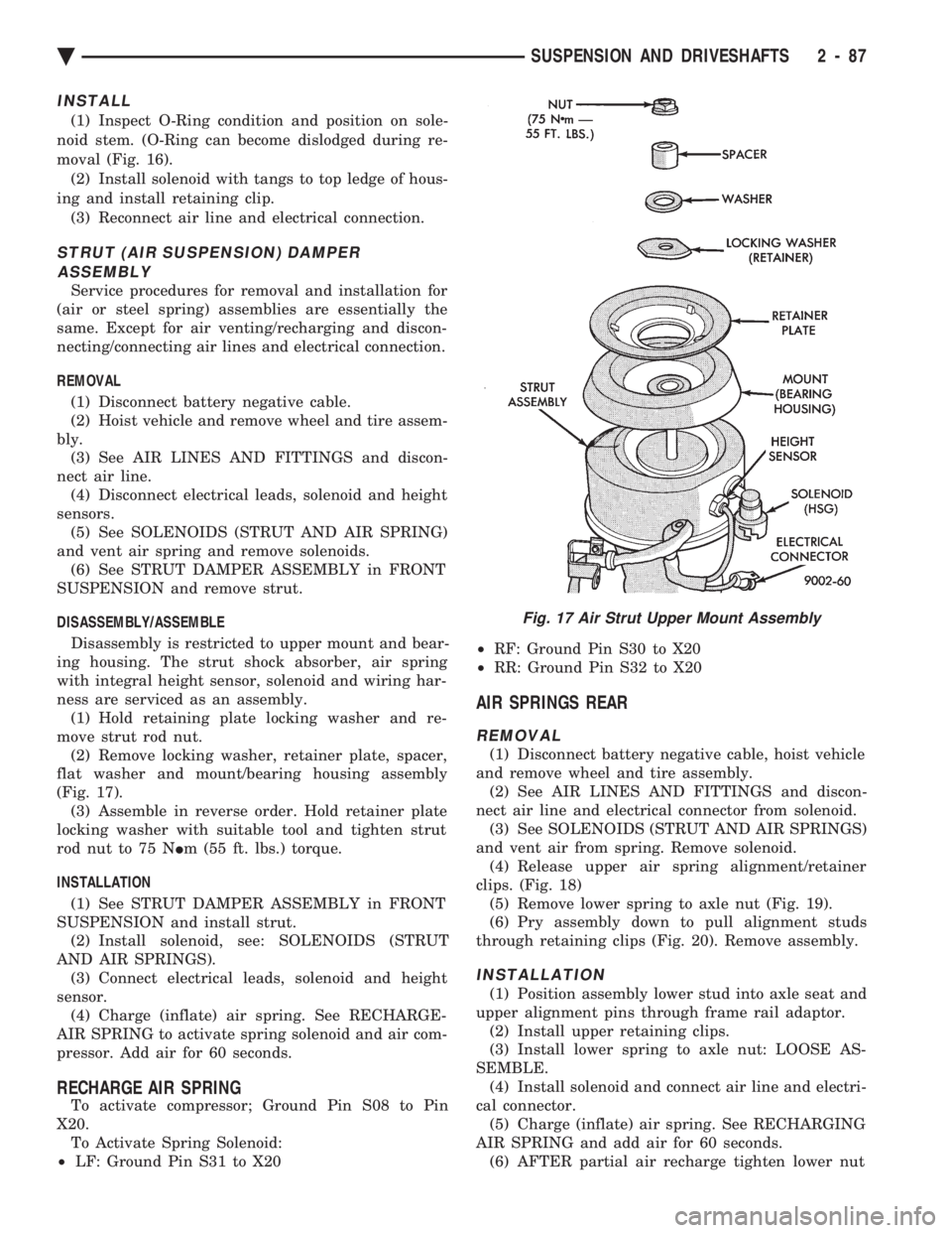
ness are serviced as an assembly. (1) Hold retaining plate locking washer and re-
move strut rod nut. (2) Remove locking washer, retainer plate, spacer,
flat washer and mount/bearing housing assembly
(Fig. 17). (3) Assemble in reverse order. Hold retainer plate
locking washer with suitable tool and tighten strut
rod nut to 75 N Im (55 ft. lbs.) torque.
INSTALLATION (1) See STRUT DAMPER ASSEMBLY in FRONT
SUSPENSION and install strut. (2) Install solenoid, see: SOLENOIDS (STRUT
AND AIR SPRINGS). (3) Connect electrical leads, solenoid and height
sensor. (4) Charge (inflate) air spring. See RECHARGE-
AIR SPRING to activate spring solenoid and air com-
pressor. Add air for 60 seconds.
RECHARGE AIR SPRING
To activate compressor; Ground Pin S08 to Pin
X20. To Activate Spring Solenoid:
² LF: Ground Pin S31 to X20 ²
RF: Ground Pin S30 to X20
² RR: Ground Pin S32 to X20
AIR SPRINGS REAR
REMOVAL
(1) Disconnect battery negative cable, hoist vehicle
and remove wheel and tire assembly. (2) See AIR LINES AND FITTINGS and discon-
nect air line and electrical connector from solenoid. (3) See SOLENOIDS (STRUT AND AIR SPRINGS)
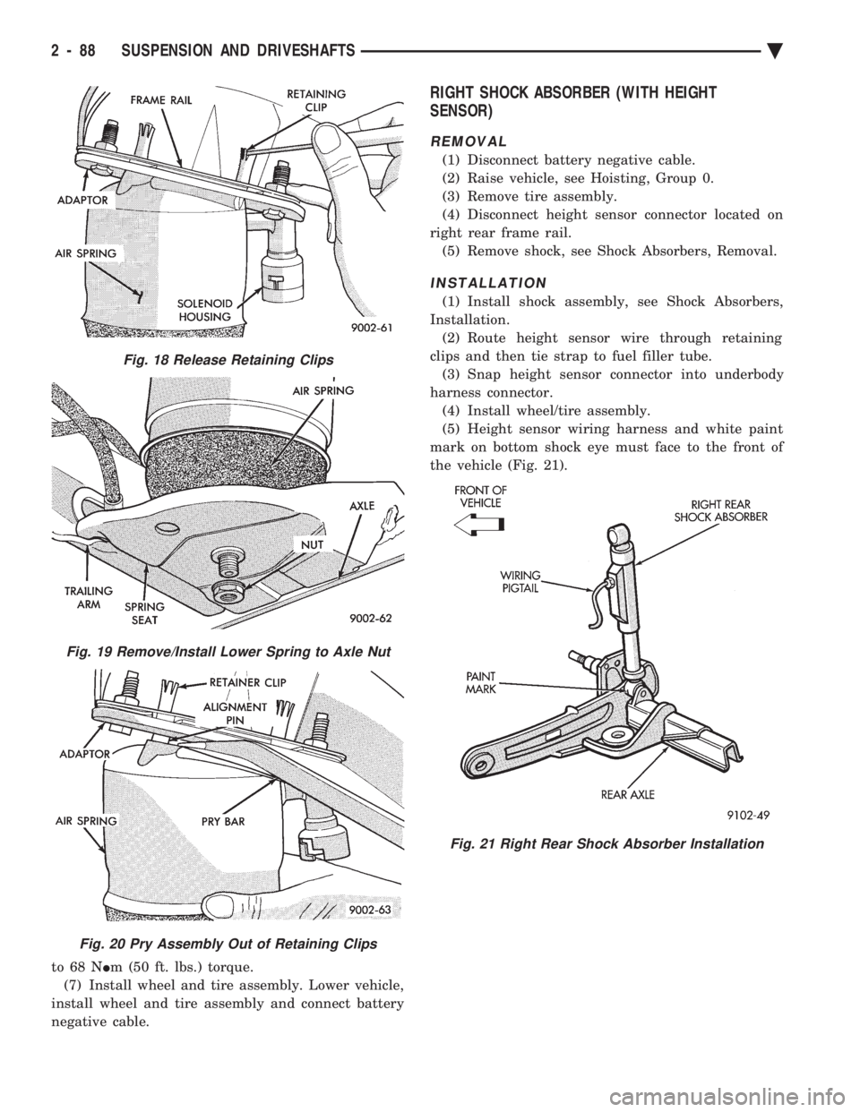
and vent air from spring. Remove solenoid. (4) Release upper air spring alignment/retainer
clips. (Fig. 18) (5) Remove lower spring to axle nut (Fig. 19).
(6) Pry assembly down to pull alignment studs
through retaining clips (Fig. 20). Remove assembly.
INSTALLATION
(1) Position assembly lower stud into axle seat and
upper alignment pins through frame rail adaptor. (2) Install upper retaining clips.
(3) Install lower spring to axle nut: LOOSE AS-
SEMBLE. (4) Install solenoid and connect air line and electri-
cal connector. (5) Charge (inflate) air spring. See RECHARGING
AIR SPRING and add air for 60 seconds. (6) AFTER partial air recharge tighten lower nut
Fig. 17 Air Strut Upper Mount Assembly
Ä SUSPENSION AND DRIVESHAFTS 2 - 87
Page 146 of 2438
to 68 N Im (50 ft. lbs.) torque.
(7) Install wheel and tire assembly. Lower vehicle,
install wheel and tire assembly and connect battery
negative cable.
RIGHT SHOCK ABSORBER (WITH HEIGHT
SENSOR)
REMOVAL
(1) Disconnect battery negative cable.
(2) Raise vehicle, see Hoisting, Group 0.
(3) Remove tire assembly.
(4) Disconnect height sensor connector located on
right rear frame rail. (5) Remove shock, see Shock Absorbers, Removal.
INSTALLATION
(1) Install shock assembly, see Shock Absorbers,
Installation. (2) Route height sensor wire through retaining
clips and then tie strap to fuel filler tube. (3) Snap height sensor connector into underbody
harness connector. (4) Install wheel/tire assembly.
(5) Height sensor wiring harness and white paint
mark on bottom shock eye must face to the front of
the vehicle (Fig. 21).
Fig. 18 Release Retaining Clips
Fig. 19 Remove/Install Lower Spring to Axle Nut
Fig. 20 Pry Assembly Out of Retaining Clips
Fig. 21 Right Rear Shock Absorber Installation
2 - 88 SUSPENSION AND DRIVESHAFTS Ä
Page 151 of 2438
BRAKES
CONTENTS
page page
ANTI-LOCK BRAKE SYSTEMÐBENDIX ANTI-LOCK 10 AC/Y BODY ............. 72
ANTI-LOCK BRAKE SYSTEMÐBENDIX ANTI-LOCK 6 AA,AG,AJ,AP BODY ....... 113
BRAKE DISC (ROTOR) ................... 53
BRAKE SUPPORT ASSEMBLY ............. 25
FRONT DISC BRAKES ................... 31
GENERAL INFORMATION .................. 1
HYDRAULIC SYSTEM CONTROL VALVES . . . 26
KELSEY HAYES DOUBLE PIN FAMILY CALIPER ............................ 35 KELSEY HAYES DOUBLE PIN NON-FAMILY
CALIPER ............................ 38
MASTER CYLINDER ..................... 66
PARKING BRAKES ...................... 57
POWER BRAKES ....................... 68
REAR DISC BRAKES .................... 45
REAR WHEEL DRUM BRAKES ............ 18
SERVICE ADJUSTMENTS .................. 4
WHEEL BEARINGS ...................... 70
WHEEL CYLINDERS ..................... 23
GENERAL INFORMATION
Throughout this group, references may be made to
a particular vehicle by letter or number designation.
A chart showing the break down of these designa-
tions is included in the Introduction Section at the
front of this service manual. Standard brake equipment consists of:
² Double pin floating caliper disc front brakes.
² Rear automatic adjusting drum brakes.
² Differential valve with a brake warning switch.
² Master cylinder.
² Vacuum power booster.
² Double pin floating caliper rear disc brakes are
available on some models. The Bendix Anti-Lock 10 braking system, uses the
standard power brake system caliper assemblies,
braking discs, pedal assembly, brake lines and hoses.
The unique parts of the Bendix Anti-Lock 10 braking
system consists of the following components. Propor-
tioning valves, wheel speed sensors, tone wheels,
electronic control unit, modulator assembly and hy-
draulic assembly. These components replace the con-
ventional master cylinder and power booster. The
components will be described in detail in the Bendix
Anti-Lock 10 brake section in this group of the ser-
vice manual. The Bendix Anti-Lock 6 braking system, uses the
following standard brake system components. Master
cylinder, power booster, caliper assemblies, braking
discs, pedal assembly, brake lines and hoses. The
unique parts of the Bendix Anti-Lock 6 braking sys-
tem consists of the following components. Modulator
assembly, unique proportioning valves, wheel speed
sensors, tone wheels, and electronic control unit.
These components will be described in detail in the
Bendix Anti-Lock 6 brake section in this group of the
service manual. The front disc brake shoes have semi-metallic lin-
ings. The hydraulic brake system (Fig .123and4)is
diagonally split on both the Non-ABS and ABS brak-
ing system. With the left front and right rear brakes
on one hydraulic system and the right front and left
rear on the other. The Non-ABS and ABS brake system may use dif-
ferent types of brake line fittings and tubing flares.
The Non-ABS brake system uses double wall tubing
flares and fittings at all tubing joint locations. Some
ABS brake systems use both ISO style tubing flares
and double wall tubing flares and corresponding fit-
tings at different joint locations. See (Figs . 2 3 and 4)
for specific joint locations and type of tubing flare. The front disc brakes consist of two different types
of caliper assemblies. A double pin Kelsey-Hayes cal-
iper (family caliper) with a bolt-on adapter attached
to the steering knuckle. Or a double pin Kelsey-
Hayes caliper (non-family caliper) which mounts di-
rectly to rails on the steering knuckle. The non-
family caliper is only used on the AY Body
(Imperials).
CAUTION: Caliper pistons, boots and seals for the
different caliper assemblies used on the front and
rear disc brake assemblies are not interchangeable.
Misusage could result in a complete brake system
failure. Be sure that the parts are replaced with the
correct replacement parts, refer to the parts book
for the type and model year of the vehicle being
worked on.
The master cylinder is anodized, lightweight alu-
minum, with a bore size of 24.0mm, 21.0mm or 7/8
inch.
Ä BRAKES 5 - 1