fuel pump CHEVROLET DYNASTY 1993 Service Manual
[x] Cancel search | Manufacturer: CHEVROLET, Model Year: 1993, Model line: DYNASTY, Model: CHEVROLET DYNASTY 1993Pages: 2438, PDF Size: 74.98 MB
Page 40 of 2438

LUBRICANTS AND GREASES
Lubricating grease is rated for quality and usage
by the NLGI. All approved products have the NLGI
symbol on the label. At the bottom NLGI symbol is the usage and qual-
ity identification letters. Wheel bearing lubricant is
identified by the letter ``G''. Chassis lubricant is iden-
tified by the letter ``L''. The letter following the us-
age letter indicates the quality of the lubricant. The
following symbols indicate the highest quality.
FLUID CAPACITIES
Fuel Tank
AP,AG and AJ ......................................53 L (14 gal.)
AA,AC and AY .....................................60 L (16 gal.)
AA-Flexible Fuel ..................................68 L (18 gal.)
Engine Oil
All.........................................................3.8 L (4.5 qts.)
Cooling System
2.2L ......................................................8.5 L (9.0 qts.)
2.5L ......................................................8.5 L (9.0 qts.)
3.0L ......................................................9.0 L (9.5 qts.)
3.3L ......................................................9.0 L (9.5 qts.)
3.8L ......................................................9.0 L (9.5 qts.)
Includes heater and coolant recovery bottle
Automatic Transaxle
Estimated Service Fill
ALL ......................................................3.8 L (4.0 qts.)
Overhaul Fill Capacity with Torque Converter
Empty
3-speed Fleet .......................................8.7 L (9.2 qts.)
3-speed .................................................8.2 L (8.8 qts.)
4-speed Electronic ................................9.4L (9.9 qts.)
Manual Transaxle
All ..........................................................9.4L (9.9 qts.)
Fill to bottom of fill hole.
Power Steering
All ...........................................................75L (1.5 pts.)
PARTS REQUIRING NO LUBRICATION
Many components on a Chrysler Corporation vehi-
cle require no periodic maintenance. Some compo-
nents are sealed and permanently lubricated. Rubber
bushings can deteriorate or limit damping ability if
lubricated. The following list of components require
no lubrication: ²
Air Pump
² Generator Bushings
² Drive Belts
² Drive Belt Idler/Tensioner Pulley
² Front Wheel Bearings
² Rubber Bushings
² Starter Bearings/Bushings
² Suspension Strut Bearings
² Throttle Control Cable
² Throttle Linkage
² Water Pump Bearings
JUMP STARTING PROCEDURE
WARNING: REVIEW ALL SAFETY PRECAUTIONS
AND WARNINGS IN GROUP 8A, BATTERY/START-
ING/CHARGING SYSTEMS DIAGNOSTICS. DO NOT JUMP START A FROZEN BATTERY, PER-
SONAL INJURY CAN RESULT. DO NOT JUMP START WHEN BATTERY INDICA-
TOR DOT IS YELLOW OR BRIGHT COLOR. DO NOT ALLOW JUMPER CABLE CLAMPS TO
TOUCH EACH OTHER WHEN CONNECTED TO A
BOOSTER SOURCE. DO NOT USE OPEN FLAME NEAR BATTERY.
REMOVE METALLIC JEWELRY WORN ON HANDS
OR WRISTS TO AVOID INJURY BY ACCIDENTAL
ARCHING OF BATTERY CURRENT. WHEN USING A HIGH OUTPUT BOOSTING DE-
VICE, DO NOT ALLOW BATTERY VOLTAGE TO EX-
CEED 16 VOLTS. REFER TO INSTRUCTIONS
PROVIDED WITH DEVICE BEING USED.
CAUTION: When using another vehicle as a
booster, do not allow vehicles to touch. Electrical
systems can be damaged on either vehicle.
TO JUMP START A DISABLED VEHICLE:
(1) Raise hood on disabled vehicle and visually in-
spect engine compartment for:
² Battery cable clamp condition, clean if necessary.
² Frozen battery.
² Yellow or bright color test indicator, if equipped.
² Low battery fluid level.
² Generator drive belt condition and tension.
² Fuel fumes or leakage, correct if necessary.
CAUTION: If the cause of starting problem on dis-
abled vehicle is severe, damage to booster vehicle
charging system can result.
(2) When using another vehicle as a booster
source, turn off all accessories, place gear selector in
park or neutral, set park brake and operate engine
at 1200 rpm.
NLGI SYMBOL
0 - 4 LUBRICATION AND MAINTENANCE Ä
Page 58 of 2438
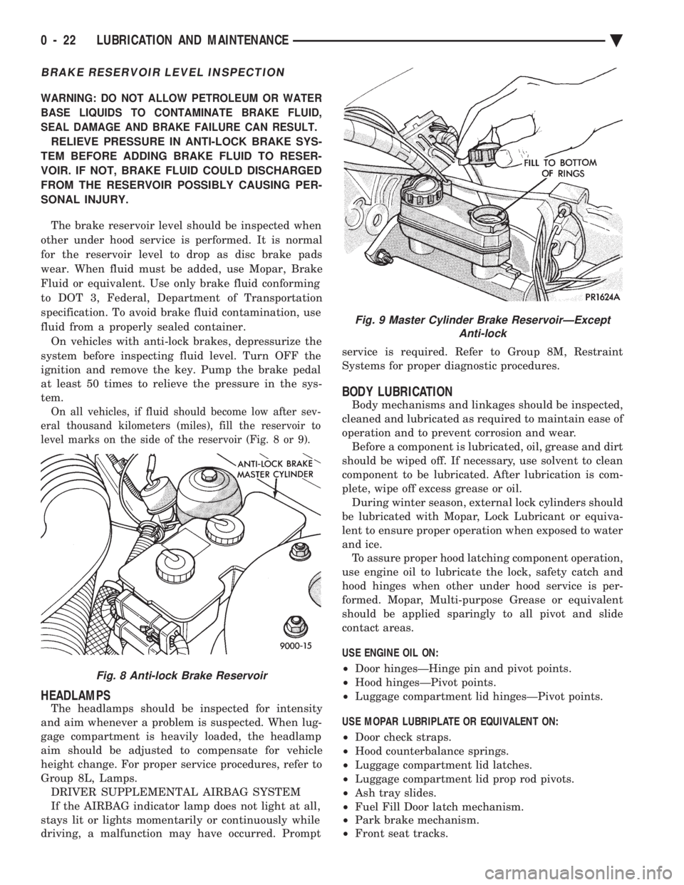
BRAKE RESERVOIR LEVEL INSPECTION
WARNING: DO NOT ALLOW PETROLEUM OR WATER
BASE LIQUIDS TO CONTAMINATE BRAKE FLUID,
SEAL DAMAGE AND BRAKE FAILURE CAN RESULT.
RELIEVE PRESSURE IN ANTI-LOCK BRAKE SYS-
TEM BEFORE ADDING BRAKE FLUID TO RESER-
VOIR. IF NOT, BRAKE FLUID COULD DISCHARGED
FROM THE RESERVOIR POSSIBLY CAUSING PER-
SONAL INJURY.
The brake reservoir level should be inspected when
other under hood service is performed. It is normal
for the reservoir level to drop as disc brake pads
wear. When fluid must be added, use Mopar, Brake
Fluid or equivalent. Use only brake fluid conforming
to DOT 3, Federal, Department of Transportation
specification. To avoid brake fluid contamination, use
fluid from a properly sealed container. On vehicles with anti-lock brakes, depressurize the
system before inspecting fluid level. Turn OFF the
ignition and remove the key. Pump the brake pedal
at least 50 times to relieve the pressure in the sys-
tem.
On all vehicles, if fluid should become low after sev-
eral thousand kilometers (miles), fill the reservoir to
level marks on the side of the reservoir (Fig. 8 or 9).
HEADLAMPS
The headlamps should be inspected for intensity
and aim whenever a problem is suspected. When lug-
gage compartment is heavily loaded, the headlamp
aim should be adjusted to compensate for vehicle
height change. For proper service procedures, refer to
Group 8L, Lamps. DRIVER SUPPLEMENTAL AIRBAG SYSTEM
If the AIRBAG indicator lamp does not light at all,
stays lit or lights momentarily or continuously while
driving, a malfunction may have occurred. Prompt service is required. Refer to Group 8M, Restraint
Systems for proper diagnostic procedures.
BODY LUBRICATION
Body mechanisms and linkages should be inspected,
cleaned and lubricated as required to maintain ease of
operation and to prevent corrosion and wear. Before a component is lubricated, oil, grease and dirt
should be wiped off. If necessary, use solvent to clean
component to be lubricated. After lubrication is com-
plete, wipe off excess grease or oil. During winter season, external lock cylinders should
be lubricated with Mopar, Lock Lubricant or equiva-
lent to ensure proper operation when exposed to water
and ice. To assure proper hood latching component operation,
use engine oil to lubricate the lock, safety catch and
hood hinges when other under hood service is per-
formed. Mopar, Multi-purpose Grease or equivalent
should be applied sparingly to all pivot and slide
contact areas.
USE ENGINE OIL ON:
² Door hingesÐHinge pin and pivot points.
² Hood hingesÐPivot points.
² Luggage compartment lid hingesÐPivot points.
USE MOPAR LUBRIPLATE OR EQUIVALENT ON:
² Door check straps.
² Hood counterbalance springs.
² Luggage compartment lid latches.
² Luggage compartment lid prop rod pivots.
² Ash tray slides.
² Fuel Fill Door latch mechanism.
² Park brake mechanism.
² Front seat tracks.
Fig. 8 Anti-lock Brake Reservoir
Fig. 9 Master Cylinder Brake ReservoirÐExcept
Anti-lock
0 - 22 LUBRICATION AND MAINTENANCE Ä
Page 443 of 2438
IGNITION SYSTEMS
CONTENTS
page page
2.2L TBI, 2.5L TBI, 2.5L MPI AND 3.0L IGNITION SYSTEMSÐDIAGNOSTIC PROCEDURES
..... 11
2.2L TBI, 2.5L TBI, 2.5L MPI AND 3.0L IGNI- TION SYSTEMSÐSERVICE PROCEDURES . 14
2.2L TBI, 2.5L TBI, 2.5L MPI AND 3.0L IGNI- TION SYSTEMSÐSYSTEM OPERATION .... 1
2.2L TURBO III, 3.3L AND 3.8L IGNITION SYSTEMÐDIAGNOSTIC PROCEDURES
.... 35
2.2L TURBO III, 3.3L AND 3.8L IGNITION SYSTEMÐSYSTEM OPERATION ......... 24
2.2L TURBO III, 3.3L AND 3.8L IGNITION SYSTEMSÐSERVICE PROCEDURES ...... 39
IGNITION SWITCH ...................... 45
SPECIFICATIONS ....................... 47
GENERAL INFORMATION
Throughout this group, references are made to par-
ticular vehicles by letter designation. A chart ex-
plaining the designations appears in the Introduction
Section of this manual.
2.2L TBI, 2.5L TBI, 2.5L MPI AND 3.0L IGNITION SYSTEMSÐSYSTEM OPERATION
INDEX
page page
Auto Shutdown (ASD) Relay and Fuel Pump Relay . 8
Coolant Temperature Sensor ................. 7
Distributor Cap ........................... 1
Distributor Pick-UpÐ3.0L Engine .............. 7
Distributor Pick-UpÐPCM Input ............... 6
General Information ........................ 1 Ignition Coil
.............................. 9
Manifold Absolute Pressure (MAP) Sensor ...... 8
Powertrain Control Module (PCM) ............. 6
Rotor .................................. 2
Spark Plug Cables ........................ 2
Spark Plugs ............................. 3
GENERAL INFORMATION
This section describes the ignition systems of the
2.2L TBI, 2.5L TBI, 2.5L MPI (flexible fuel AA-body)
and 3.0L engines. The Fuel Injection sections of Group 14 explain On
Board Diagnostics. Group 0, Lubrication and Maintenance, contains
general maintenance information for ignition related
items. The Owner's Manual also contains mainte-
nance information.
DISTRIBUTOR CAP
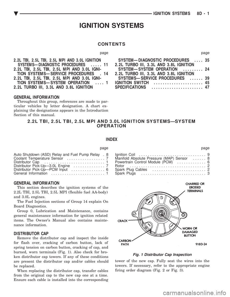
Remove the distributor cap and inspect the inside
for flash over, cracking of carbon button, lack of
spring tension on carbon button, cracking of cap, and
burned, worn terminals (Fig. 1). Also check for bro-
ken distributor cap towers. If any of these conditions
are present the distributor cap and/or cables should
be replaced. When replacing the distributor cap, transfer cables
from the original cap to the new cap one at a time.
Ensure each cable is installed into the corresponding tower of the new cap. Fully seat the wires into the
towers. If necessary, refer to the appropriate engine
firing order diagram (Fig. 2 or Fig. 3).
Fig. 1 Distributor Cap Inspection
Ä
IGNITION SYSTEMS 8D - 1
Page 450 of 2438
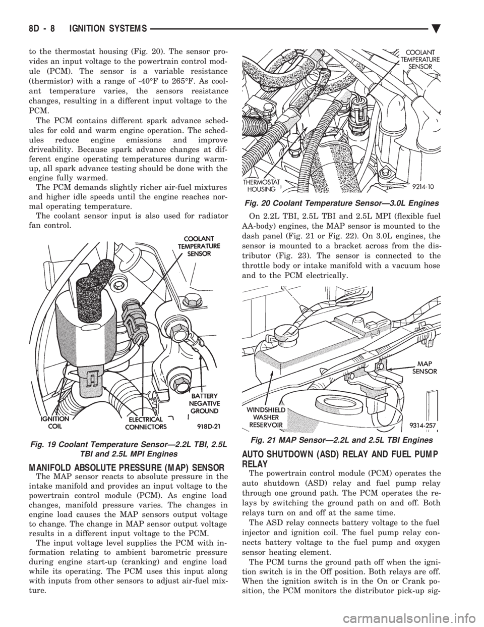
to the thermostat housing (Fig. 20). The sensor pro-
vides an input voltage to the powertrain control mod-
ule (PCM). The sensor is a variable resistance
(thermistor) with a range of -40ÉF to 265ÉF. As cool-
ant temperature varies, the sensors resistance
changes, resulting in a different input voltage to the
PCM. The PCM contains different spark advance sched-
ules for cold and warm engine operation. The sched-
ules reduce engine emissions and improve
driveability. Because spark advance changes at dif-
ferent engine operating temperatures during warm-
up, all spark advance testing should be done with the
engine fully warmed. The PCM demands slightly richer air-fuel mixtures
and higher idle speeds until the engine reaches nor-
mal operating temperature. The coolant sensor input is also used for radiator
fan control.
MANIFOLD ABSOLUTE PRESSURE (MAP) SENSOR
The MAP sensor reacts to absolute pressure in the
intake manifold and provides an input voltage to the
powertrain control module (PCM). As engine load
changes, manifold pressure varies. The changes in
engine load causes the MAP sensors output voltage
to change. The change in MAP sensor output voltage
results in a different input voltage to the PCM. The input voltage level supplies the PCM with in-
formation relating to ambient barometric pressure
during engine start-up (cranking) and engine load
while its operating. The PCM uses this input along
with inputs from other sensors to adjust air-fuel mix-
ture. On 2.2L TBI, 2.5L TBI and 2.5L MPI (flexible fuel
AA-body) engines, the MAP sensor is mounted to the
dash panel (Fig. 21 or Fig. 22). On 3.0L engines, the
sensor is mounted to a bracket across from the dis-
tributor (Fig. 23). The sensor is connected to the
throttle body or intake manifold with a vacuum hose
and to the PCM electrically.
AUTO SHUTDOWN (ASD) RELAY AND FUEL PUMP
RELAY
The powertrain control module (PCM) operates the
auto shutdown (ASD) relay and fuel pump relay
through one ground path. The PCM operates the re-
lays by switching the ground path on and off. Both
relays turn on and off at the same time. The ASD relay connects battery voltage to the fuel
injector and ignition coil. The fuel pump relay con-
nects battery voltage to the fuel pump and oxygen
sensor heating element. The PCM turns the ground path off when the igni-
tion switch is in the Off position. Both relays are off.
When the ignition switch is in the On or Crank po-
sition, the PCM monitors the distributor pick-up sig-
Fig. 19 Coolant Temperature SensorÐ2.2L TBI, 2.5L TBI and 2.5L MPI Engines
Fig. 20 Coolant Temperature SensorÐ3.0L Engines
Fig. 21 MAP SensorÐ2.2L and 2.5L TBI Engines
8D - 8 IGNITION SYSTEMS Ä
Page 451 of 2438
nal. From the pick-up signal, the PCM determines
engine speed and ignition timing (coil dwell). If the
PCM does not receive a distributor signal when the
ignition switch is in the Run position, it will de-en-
ergize both relays. When the relays are de-energized,
battery voltage is not supplied to the fuel injector, ig-
nition coil, fuel pump and oxygen sensor heating el-
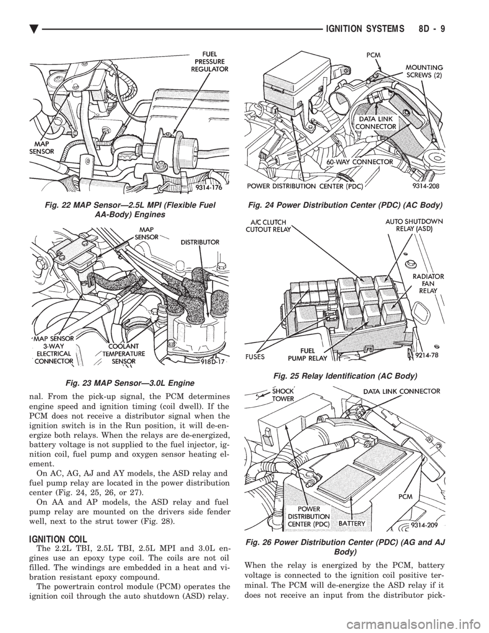
ement. On AC, AG, AJ and AY models, the ASD relay and
fuel pump relay are located in the power distribution
center (Fig. 24, 25, 26, or 27). On AA and AP models, the ASD relay and fuel
pump relay are mounted on the drivers side fender
well, next to the strut tower (Fig. 28).
IGNITION COIL
The 2.2L TBI, 2.5L TBI, 2.5L MPI and 3.0L en-
gines use an epoxy type coil. The coils are not oil
filled. The windings are embedded in a heat and vi-
bration resistant epoxy compound. The powertrain control module (PCM) operates the
ignition coil through the auto shutdown (ASD) relay. When the relay is energized by the PCM, battery
voltage is connected to the ignition coil positive ter-
minal. The PCM will de-energize the ASD relay if it
does not receive an input from the distributor pick-
Fig. 22 MAP SensorÐ2.5L MPI (Flexible Fuel AA-Body) Engines
Fig. 23 MAP SensorÐ3.0L Engine
Fig. 24 Power Distribution Center (PDC) (AC Body)
Fig. 25 Relay Identification (AC Body)
Fig. 26 Power Distribution Center (PDC) (AG and AJ Body)
Ä IGNITION SYSTEMS 8D - 9
Page 452 of 2438
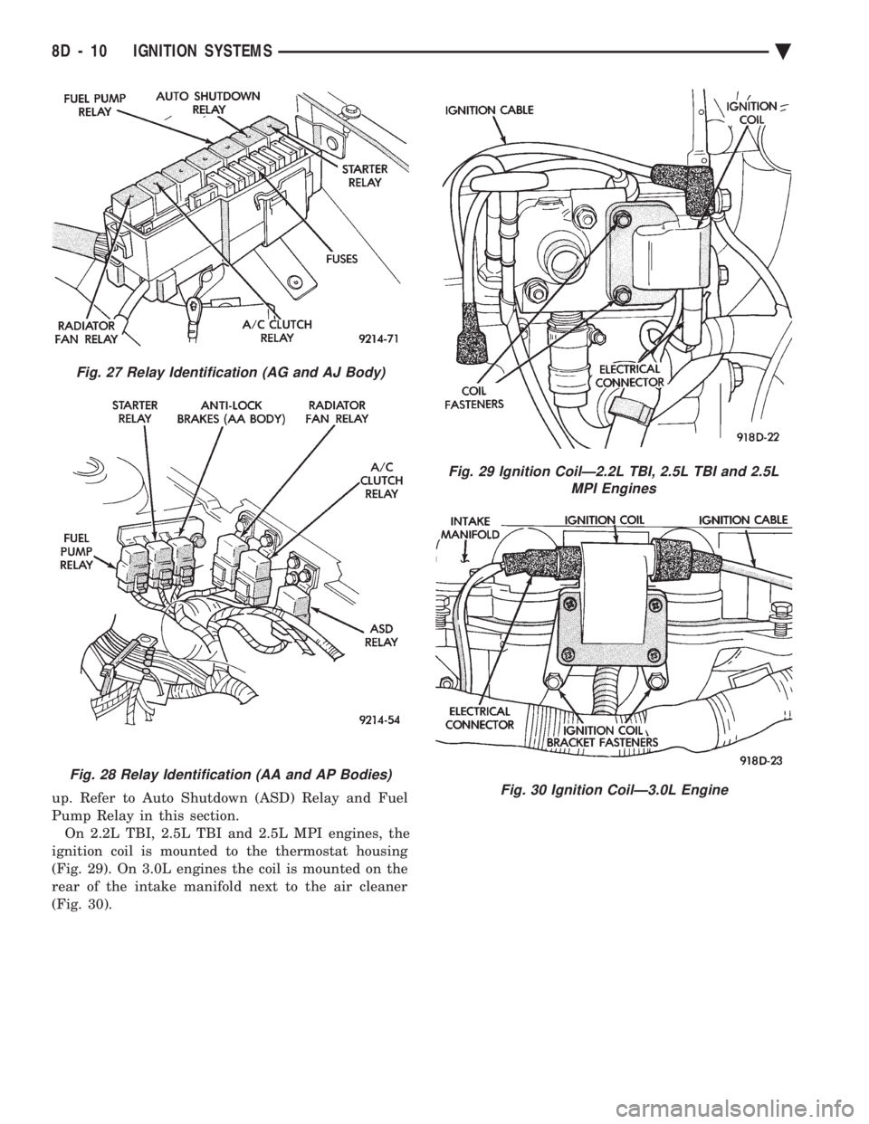
up. Refer to Auto Shutdown (ASD) Relay and Fuel
Pump Relay in this section.On 2.2L TBI, 2.5L TBI and 2.5L MPI engines, the
ignition coil is mounted to the thermostat housing
(Fig. 29). On 3.0L engines the coil is mounted on the
rear of the intake manifold next to the air cleaner
(Fig. 30).
Fig. 28 Relay Identification (AA and AP Bodies)
Fig. 29 Ignition CoilÐ2.2L TBI, 2.5L TBI and 2.5L MPI Engines
Fig. 30 Ignition CoilÐ3.0L Engine
Fig. 27 Relay Identification (AG and AJ Body)
8D - 10 IGNITION SYSTEMS Ä
Page 466 of 2438
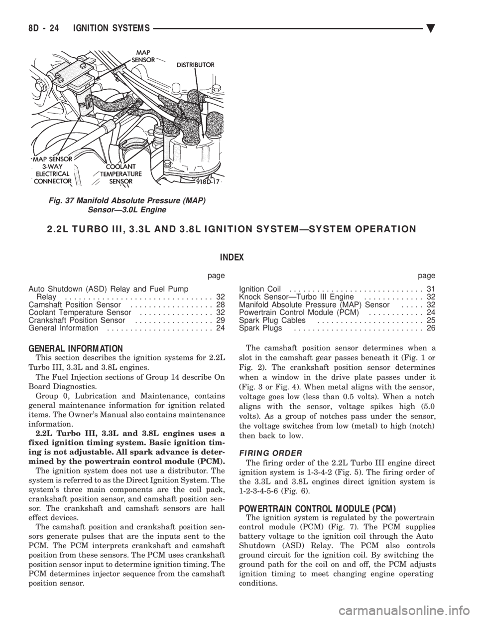
2.2L TURBO III, 3.3L AND 3.8L IGNITION SYSTEMÐSYSTEM OPERATION INDEX
page page
Auto Shutdown (ASD) Relay and Fuel Pump Relay ................................ 32
Camshaft Position Sensor .................. 28
Coolant Temperature Sensor ................ 32
Crankshaft Position Sensor ................. 29
General Information ....................... 24 Ignition Coil
............................. 31
Knock SensorÐTurbo III Engine ............. 32
Manifold Absolute Pressure (MAP) Sensor ..... 32
Powertrain Control Module (PCM) ............ 24
Spark Plug Cables ....................... 25
Spark Plugs ............................ 26
GENERAL INFORMATION
This section describes the ignition systems for 2.2L
Turbo III, 3.3L and 3.8L engines. The Fuel Injection sections of Group 14 describe On
Board Diagnostics. Group 0, Lubrication and Maintenance, contains
general maintenance information for ignition related
items. The Owner's Manual also contains maintenance
information. 2.2L Turbo III, 3.3L and 3.8L engines uses a
fixed ignition timing system. Basic ignition tim-
ing is not adjustable. All spark advance is deter-
mined by the powertrain control module (PCM). The ignition system does not use a distributor. The
system is referred to as the Direct Ignition System. The
system's three main components are the coil pack,
crankshaft position sensor, and camshaft position sen-
sor. The crankshaft and camshaft sensors are hall
effect devices. The camshaft position and crankshaft position sen-
sors generate pulses that are the inputs sent to the
PCM. The PCM interprets crankshaft and camshaft
position from these sensors. The PCM uses crankshaft
position sensor input to determine ignition timing. The
PCM determines injector sequence from the camshaft
position sensor. The camshaft position sensor determines when a
slot in the camshaft gear passes beneath it (Fig. 1 or
Fig. 2). The crankshaft position sensor determines
when a window in the drive plate passes under it
(Fig. 3 or Fig. 4). When metal aligns with the sensor,
voltage goes low (less than 0.5 volts). When a notch
aligns with the sensor, voltage spikes high (5.0
volts). As a group of notches pass under the sensor,
the voltage switches from low (metal) to high (notch)
then back to low.
FIRING ORDER
The firing order of the 2.2L Turbo III engine direct
ignition system is 1-3-4-2 (Fig. 5). The firing order of
the 3.3L and 3.8L engines direct ignition system is
1-2-3-4-5-6 (Fig. 6).
POWERTRAIN CONTROL MODULE (PCM)
The ignition system is regulated by the powertrain
control module (PCM) (Fig. 7). The PCM supplies
battery voltage to the ignition coil through the Auto
Shutdown (ASD) Relay. The PCM also controls
ground circuit for the ignition coil. By switching the
ground path for the coil on and off, the PCM adjusts
ignition timing to meet changing engine operating
conditions.
Fig. 37 Manifold Absolute Pressure (MAP) SensorÐ3.0L Engine
8D - 24 IGNITION SYSTEMS Ä
Page 474 of 2438
The coil's low primary resistance allows the PCM to
fully charge the coil for each firing.
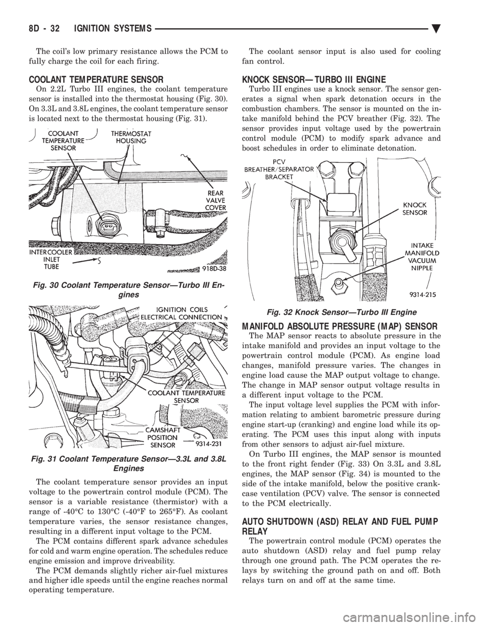
COOLANT TEMPERATURE SENSOR
On 2.2L Turbo III engines, the coolant temperature
sensor is installed into the thermostat housing (Fig. 30).
On 3.3L and 3.8L engines, the coolant temperature sensor
is located next to the thermostat housing (Fig. 31).
The coolant temperature sensor provides an input
voltage to the powertrain control module (PCM). The
sensor is a variable resistance (thermistor) with a
range of -40ÉC to 130ÉC (-40ÉF to 265ÉF). As coolant
temperature varies, the sensor resistance changes,
resulting in a different input voltage to the PCM.
The PCM contains different spark advance schedules
for cold and warm engine operation. The schedules reduce
engine emission and improve driveability.
The PCM demands slightly richer air-fuel mixtures
and higher idle speeds until the engine reaches normal
operating temperature. The coolant sensor input is also used for cooling
fan control.
KNOCK SENSORÐTURBO III ENGINE
Turbo III engines use a knock sensor. The sensor gen-
erates a signal when spark detonation occurs in the
combustion chambers. The sensor is mounted on the in-
take manifold behind the PCV breather (Fig. 32). The
sensor provides input voltage used by the powertrain
control module (PCM) to modify spark advance and
boost schedules in order to eliminate detonation.
MANIFOLD ABSOLUTE PRESSURE (MAP) SENSOR
The MAP sensor reacts to absolute pressure in the
intake manifold and provides an input voltage to the
powertrain control module (PCM). As engine load
changes, manifold pressure varies. The changes in
engine load cause the MAP output voltage to change.
The change in MAP sensor output voltage results in
a different input voltage to the PCM.
The input voltage level supplies the PCM with infor-
mation relating to ambient barometric pressure during
engine start-up (cranking) and engine load while its op-
erating. The PCM uses this input along with inputs
from other sensors to adjust air-fuel mixture.
On Turbo III engines, the MAP sensor is mounted
to the front right fender (Fig. 33) On 3.3L and 3.8L
engines, the MAP sensor (Fig. 34) is mounted to the
side of the intake manifold, below the positive crank-
case ventilation (PCV) valve. The sensor is connected
to the PCM electrically.
AUTO SHUTDOWN (ASD) RELAY AND FUEL PUMP
RELAY
The powertrain control module (PCM) operates the
auto shutdown (ASD) relay and fuel pump relay
through one ground path. The PCM operates the re-
lays by switching the ground path on and off. Both
relays turn on and off at the same time.
Fig. 32 Knock SensorÐTurbo III Engine
Fig. 30 Coolant Temperature SensorÐTurbo III En- gines
Fig. 31 Coolant Temperature SensorÐ3.3L and 3.8LEngines
8D - 32 IGNITION SYSTEMS Ä
Page 475 of 2438
The ASD relay connects battery voltage to the fuel
injector and ignition coil. The fuel pump relay con-
nects battery voltage to the fuel pump and oxygen
sensor heating element. The PCM turns the ground path off when the igni-
tion switch is in the Off position. Both relays are off.
When the ignition switch is in the On or Crank po-
sition, the PCM monitors the camshaft position sen-
sor and crankshaft position sensor signals. From
these inputs, the PCM determines engine speed and
ignition timing (coil dwell). If the PCM does not re-
ceive a camshaft position sensor signal when the ig-
nition switch is in the Run position, it will de-
energize both relays. When the relays are de-
energized, battery voltage is not supplied to the fuel
injector, ignition coil, fuel pump and oxygen sensor
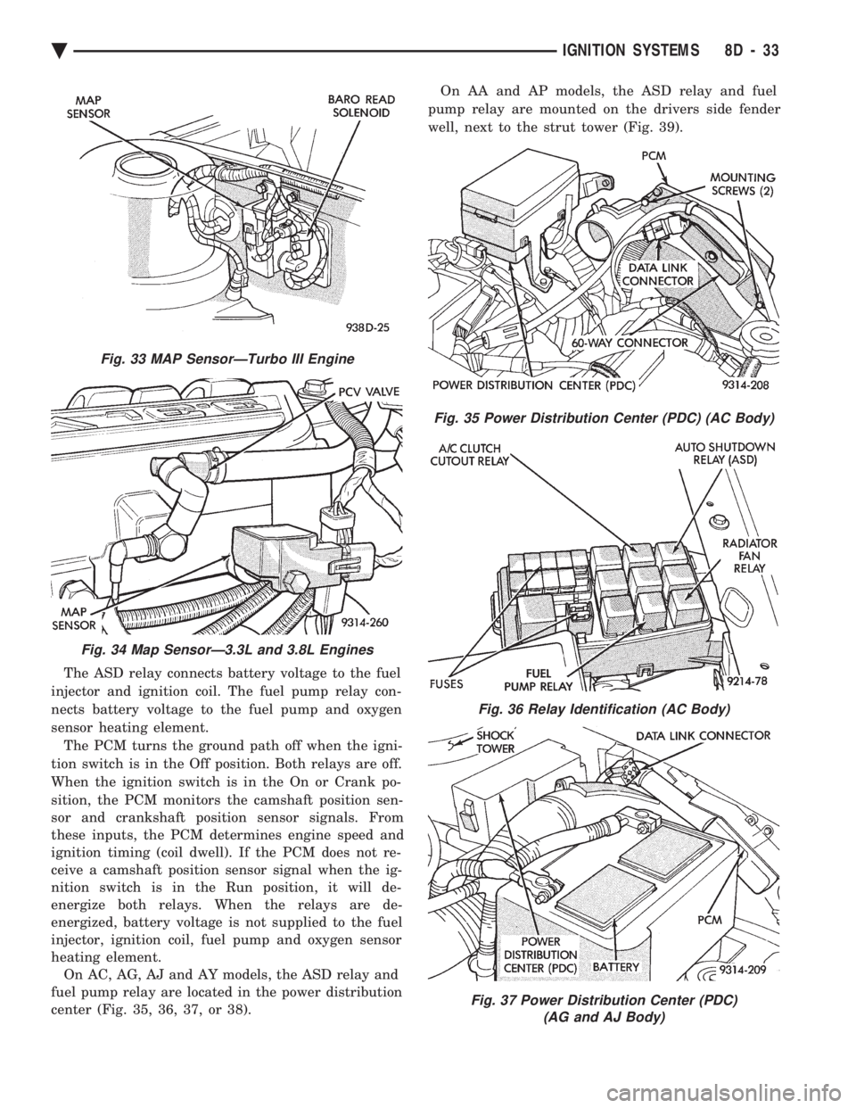
heating element. On AC, AG, AJ and AY models, the ASD relay and
fuel pump relay are located in the power distribution
center (Fig. 35, 36, 37, or 38). On AA and AP models, the ASD relay and fuel
pump relay are mounted on the drivers side fender
well, next to the strut tower (Fig. 39).
Fig. 33 MAP SensorÐTurbo III Engine
Fig. 34 Map SensorÐ3.3L and 3.8L Engines
Fig. 35 Power Distribution Center (PDC) (AC Body)
Fig. 36 Relay Identification (AC Body)
Fig. 37 Power Distribution Center (PDC) (AG and AJ Body)
Ä IGNITION SYSTEMS 8D - 33
Page 932 of 2438
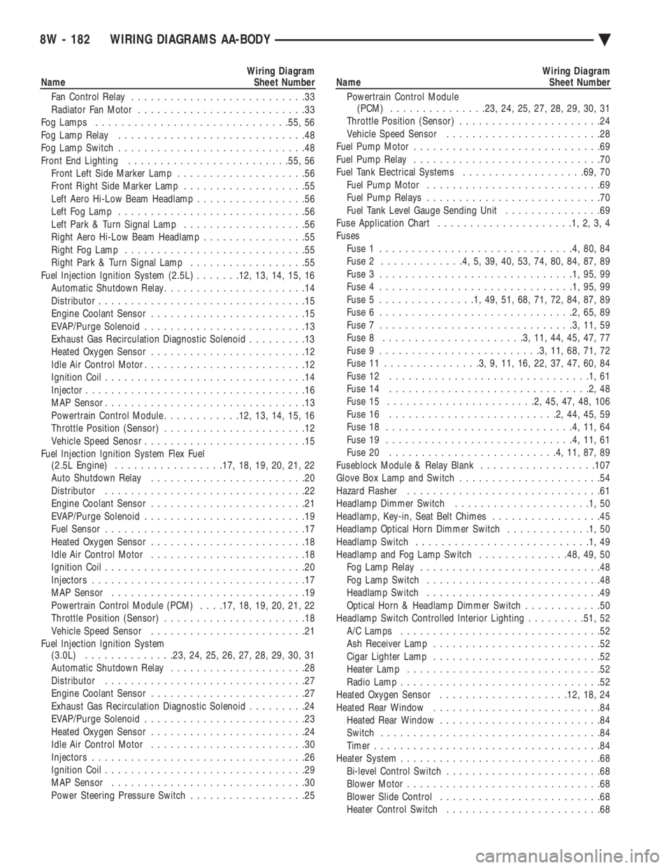
Wiring Diagram
Name Sheet Number
Fan Control Relay ...........................33
Radiator Fan Motor ..........................33
Fog Lamps ............................. .55, 56
Fog Lamp Relay .............................48
Fog Lamp Switch .............................48
Front End Lighting ........................ .55, 56
Front Left Side Marker Lamp ....................56
Front Right Side Marker Lamp ...................55
Left Aero Hi-Low Beam Headlamp .................56
Left Fog Lamp .............................56
Left Park & Turn Signal Lamp ...................56
Right Aero Hi-Low Beam Headlamp ................55
Right Fog Lamp ............................55
Right Park & Turn Signal Lamp ..................55
Fuel Injection Ignition System (2.5L) .......12, 13, 14, 15, 16
Automatic Shutdown Relay ......................14
Distributor ................................15
Engine Coolant Sensor ........................15
EVAP/Purge Solenoid .........................13
Exhaust Gas Recirculation Diagnostic Solenoid .........13
Heated Oxygen Sensor ........................12
Idle Air Control Motor .........................12
Ignition Coil ...............................14
Injector ..................................16
MAP Sensor ...............................13
Powertrain Control Module ............12, 13, 14, 15, 16
Throttle Position (Sensor) ......................12
Vehicle Speed Senosr .........................15
Fuel Injection Ignition System Flex Fuel (2.5L Engine) ................ .17, 18, 19, 20, 21, 22
Auto Shutdown Relay ........................20
Distributor ...............................22
Engine Coolant Sensor ........................21
EVAP/Purge Solenoid .........................19
Fuel Sensor ...............................17
Heated Oxygen Sensor ........................18
Idle Air Control Motor ........................18
Ignition Coil ...............................20
Injectors .................................17
MAP Sensor ..............................19
Powertrain Control Module (PCM) . . . .17, 18, 19, 20, 21, 22
Throttle Position (Sensor) ......................18
Vehicle Speed Sensor ........................21
Fuel Injection Ignition System (3.0L) ............. .23, 24, 25, 26, 27, 28, 29, 30, 31
Automatic Shutdown Relay .....................28
Distributor ...............................27
Engine Coolant Sensor ........................27
Exhaust Gas Recirculation Diagnostic Solenoid .........24
EVAP/Purge Solenoid .........................23
Heated Oxygen Sensor ........................24
Idle Air Control Motor ........................30
Injectors .................................26
Ignition Coil ...............................29
MAP Sensor ..............................30
Power Steering Pressure Switch ..................25Wiring Diagram
Name Sheet Number
Powertrain Control Module (PCM) .............. .23, 24, 25, 27, 28, 29, 30, 31
Throttle Position (Sensor) ......................24
Vehicle Speed Sensor ........................28
Fuel Pump Motor .............................69
Fuel Pump Relay .............................70
Fuel Tank Electrical Systems ...................69, 70
Fuel Pump Motor ...........................69
Fuel Pump Relays ...........................70
Fuel Tank Level Gauge Sending Unit ...............69
Fuse Application Chart .....................1,2,3,4
Fuses Fuse 1 ..............................4,80,84
Fuse 2 .............4,5,39,40,53,74,80,84,87,89
Fuse 3 ..............................1,95,99
Fuse 4 ..............................1,95,99
Fuse 5 ...............1,49,51,68,71,72,84,87,89
Fuse 6 ..............................2,65,89
Fuse 7 ..............................3,11,59
Fuse 8 ......................3,11,44,45,47,77
Fuse 9 .........................3,11,68,71,72
Fuse 11 ...............3,9,11,16,22,37,47,60,84
Fuse 12 ...............................1,61
Fuse 14 ...............................2,48
Fuse 15 .......................2,45,47,48,106
Fuse 16 ..........................2,44,45,59
Fuse 18 .............................4,11,64
Fuse 19 .............................4,11,61
Fuse 20 ..........................4,11,87,89
Fuseblock Module & Relay Blank ..................107
Glove Box Lamp and Switch ......................54
Hazard Flasher ..............................61
Headlamp Dimmer Switch .....................1,50
Headlamp, Key-in, Seat Belt Chimes .................45
Headlamp Optical Horn Dimmer Switch .............1,50
Headlamp Switch ...........................1,49
Headlamp and Fog Lamp Switch ..............48, 49, 50
Fog Lamp Relay ............................48
Fog Lamp Switch ...........................48
Headlamp Switch ...........................49
Optical Horn & Headlamp Dimmer Switch ............50
Headlamp Switch Controlled Interior Lighting .........51, 52
A/C Lamps ...............................52
Ash Receiver Lamp ..........................52
Cigar Lighter Lamp ..........................52
Heater Lamp ..............................52
Radio Lamp ...............................52
Heated Oxygen Sensor ................... .12, 18, 24
Heated Rear Window ..........................84
Heated Rear Window .........................84
Switch ..................................84
Timer ...................................84
Heater System ...............................68
Bi-level Control Switch ........................68
Blower Motor ..............................68
Blower Slide Control .........................68
Heater Control Switch ........................68
8W - 182 WIRING DIAGRAMS AA-BODY Ä