brake CHEVROLET DYNASTY 1993 Owner's Manual
[x] Cancel search | Manufacturer: CHEVROLET, Model Year: 1993, Model line: DYNASTY, Model: CHEVROLET DYNASTY 1993Pages: 2438, PDF Size: 74.98 MB
Page 75 of 2438
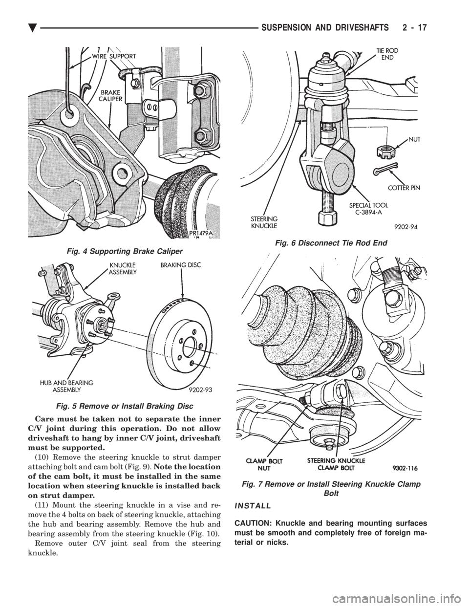
Care must be taken not to separate the inner
C/V joint during this operation. Do not allow
driveshaft to hang by inner C/V joint, driveshaft
must be supported. (10) Remove the steering knuckle to strut damper
attaching bolt and cam bolt (Fig. 9). Note the location
of the cam bolt, it must be installed in the same
location when steering knuckle is installed back
on strut damper. (11) Mount the steering knuckle in a vise and re-
move the 4 bolts on back of steering knuckle, attaching
the hub and bearing assembly. Remove the hub and
bearing assembly from the steering knuckle (Fig. 10). Remove outer C/V joint seal from the steering
knuckle.
INSTALL
CAUTION: Knuckle and bearing mounting surfaces
must be smooth and completely free of foreign ma-
terial or nicks.
Fig. 6 Disconnect Tie Rod End
Fig. 7 Remove or Install Steering Knuckle Clamp Bolt
Fig. 4 Supporting Brake Caliper
Fig. 5 Remove or Install Braking Disc
Ä SUSPENSION AND DRIVESHAFTS 2 - 17
Page 77 of 2438
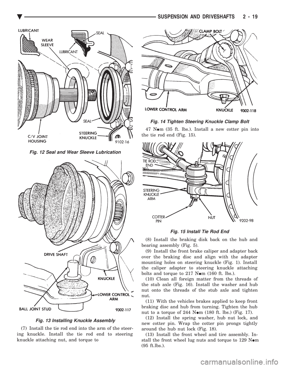
(7) Install the tie rod end into the arm of the steer-
ing knuckle. Install the tie rod end to steering
knuckle attaching nut, and torque to 47 N
Im (35 ft. lbs.). Install a new cotter pin into
the tie rod end (Fig. 15).
(8) Install the braking disk back on the hub and
bearing assembly (Fig. 5). (9) Install the front brake caliper and adapter back
over the braking disc and align with the adapter
mounting holes on steering knuckle (Fig. 1). Install
the caliper adapter to steering knuckle attaching
bolts and torque to 217 N Im (160 ft. lbs.).
(10) Clean all foreign matter from the threads of
the stub axle (Fig. 16). Install the washer and hub
nut onto the threads of the stub axle and tighten
nut. (11) With the vehicles brakes applied to keep front
braking disc and hub from turning. Tighten the hub
nut to a torque of 244 N Im (180 ft. lbs.) (Fig. 17).
(12) Install the spring washer, hub nut lock, and
new cotter pin. Wrap the cotter pin prongs tightly
around the hub nut lock (Fig. 18). (13) Install the front wheel and tire assembly. In-
stall the front wheel lug nuts and torque to 129 N Im
(95 ft.lbs.).
Fig. 13 Installing Knuckle Assembly
Fig. 12 Seal and Wear Sleeve Lubrication
Fig. 14 Tighten Steering Knuckle Clamp Bolt
Fig. 15 Install Tie Rod End
Ä SUSPENSION AND DRIVESHAFTS 2 - 19
Page 78 of 2438
(14) Lower vehicle.
(15) Align the front wheels of the vehicle. Use the
procedure listed under Wheel Alignment, in the
Front Suspension Service Procedures section of this
service manual.
HUB AND BEARING ASSEMBLY
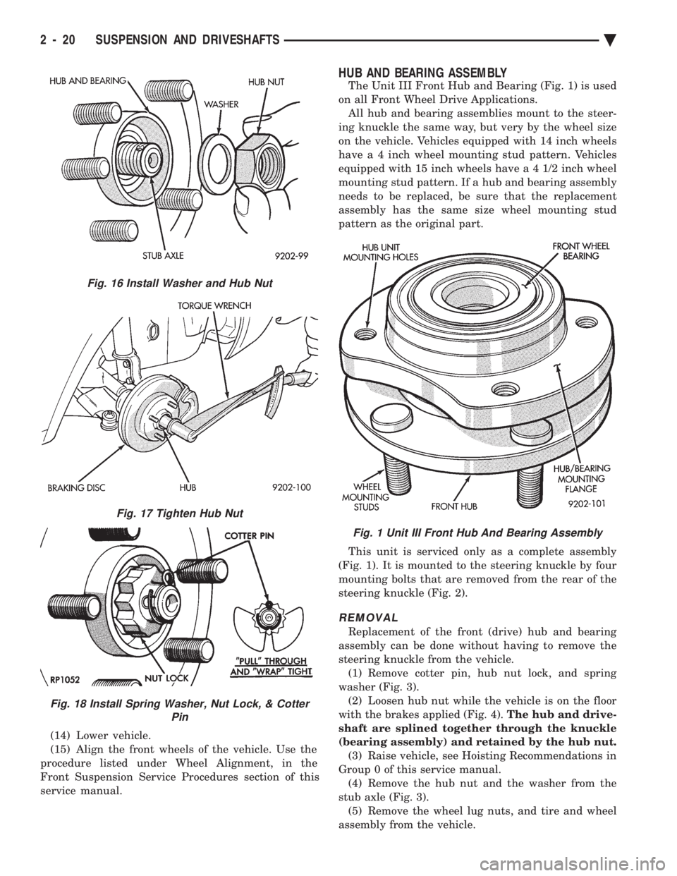
The Unit III Front Hub and Bearing (Fig. 1) is used
on all Front Wheel Drive Applications. All hub and bearing assemblies mount to the steer-
ing knuckle the same way, but very by the wheel size
on the vehicle. Vehicles equipped with 14 inch wheels
have a 4 inch wheel mounting stud pattern. Vehicles
equipped with 15 inch wheels hav e a 4 1/2 inch wheel
mounting stud pattern. If a hub and bearing assembly
needs to be replaced, be sure that the replacement
assembly has the same size wheel mounting stud
pattern as the original part.
This unit is serviced only as a complete assembly
(Fig. 1). It is mounted to the steering knuckle by four
mounting bolts that are removed from the rear of the
steering knuckle (Fig. 2).
REMOVAL
Replacement of the front (drive) hub and bearing
assembly can be done without having to remove the
steering knuckle from the vehicle. (1) Remove cotter pin, hub nut lock, and spring
washer (Fig. 3). (2) Loosen hub nut while the vehicle is on the floor
with the brakes applied (Fig. 4). The hub and drive-
shaft are splined together through the knuckle
(bearing assembly) and retained by the hub nut. (3) Raise vehicle, see Hoisting Recommendations in
Group 0 of this service manual. (4) Remove the hub nut and the washer from the
stub axle (Fig. 3). (5) Remove the wheel lug nuts, and tire and wheel
assembly from the vehicle.
Fig. 16 Install Washer and Hub Nut
Fig. 17 Tighten Hub Nut
Fig. 18 Install Spring Washer, Nut Lock, & Cotter Pin
Fig. 1 Unit III Front Hub And Bearing Assembly
2 - 20 SUSPENSION AND DRIVESHAFTS Ä
Page 80 of 2438
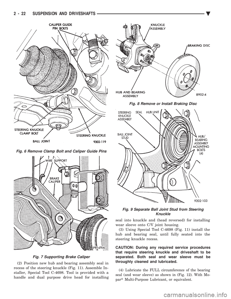
(2) Position new hub and bearing assembly seal in
recess of the steering knuckle (Fig. 11). Assemble In-
staller, Special Tool C-4698. Tool is provided with a
handle and dual purpose drive head for installing seal into knuckle and (head reversed) for installing
wear sleeve onto C/V joint housing.
(3) Using Special Tool C-4698 (Fig. 11) install the
hub and bearing seal, until fully seated into the
steering knuckle recess.
CAUTION: During any required service procedures
that require steering knuckle and driveshaft to be
separated. Both seal and wear sleeve must be
throughly cleaned and lubricated.
(4) Lubricate the FULL circumference of the bearing
seal (and wear sleeve) as shown in (Fig. 12). With Mo-
par tMulti-Purpose Lubricant, or equivalent.
Fig. 8 Remove or Install Braking Disc
Fig. 9 Separate Ball Joint Stud from Steering
Knuckle
Fig. 6 Remove Clamp Bolt and Caliper Guide Pins
Fig. 7 Supporting Brake Caliper
2 - 22 SUSPENSION AND DRIVESHAFTS Ä
Page 81 of 2438
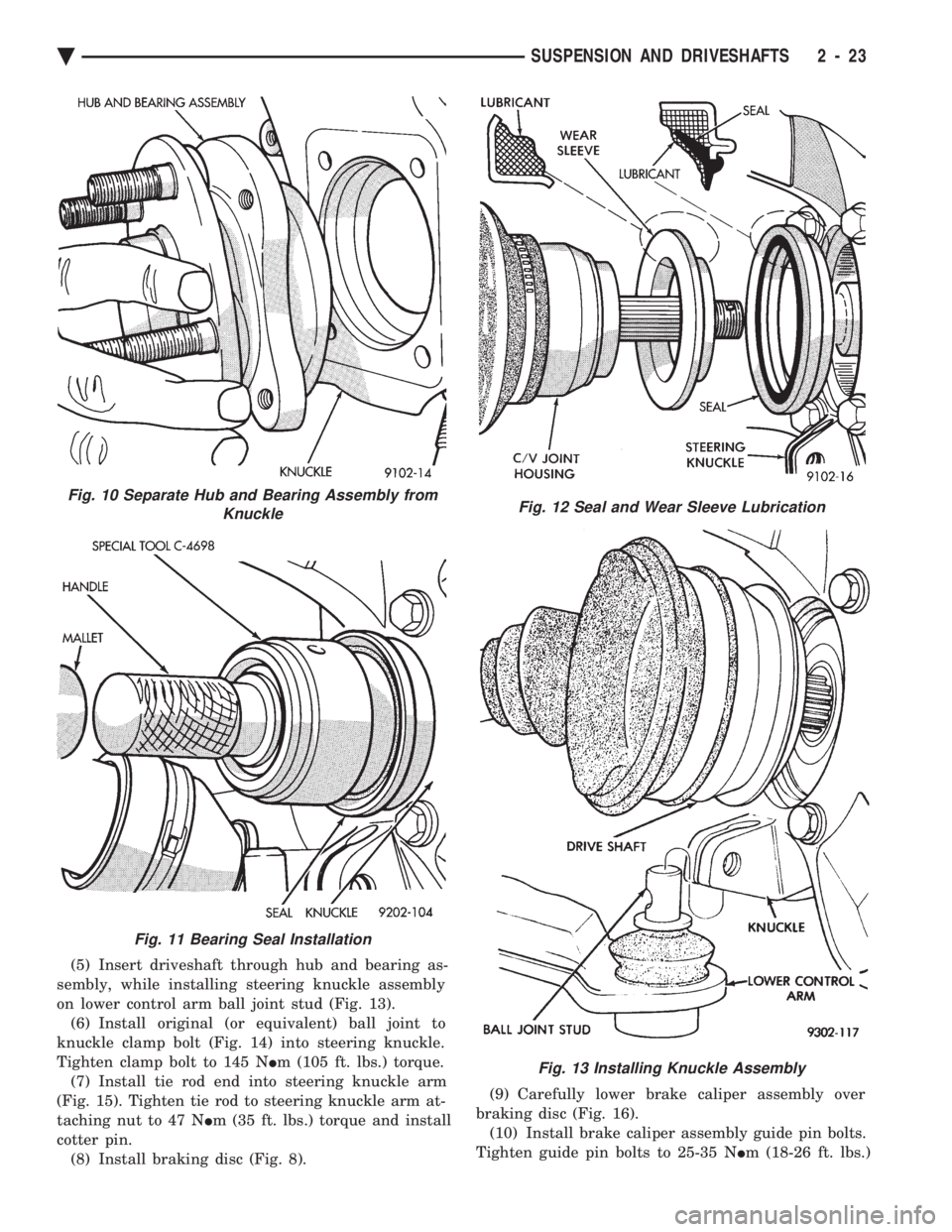
(5) Insert driveshaft through hub and bearing as-
sembly, while installing steering knuckle assembly
on lower control arm ball joint stud (Fig. 13). (6) Install original (or equivalent) ball joint to
knuckle clamp bolt (Fig. 14) into steering knuckle.
Tighten clamp bolt to 145 N Im (105 ft. lbs.) torque.
(7) Install tie rod end into steering knuckle arm
(Fig. 15). Tighten tie rod to steering knuckle arm at-
taching nut to 47 N Im (35 ft. lbs.) torque and install
cotter pin. (8) Install braking disc (Fig. 8). (9) Carefully lower brake caliper assembly over
braking disc (Fig. 16). (10) Install brake caliper assembly guide pin bolts.
Tighten guide pin bolts to 25-35 N Im (18-26 ft. lbs.)
Fig. 10 Separate Hub and Bearing Assembly from
Knuckle
Fig. 11 Bearing Seal Installation
Fig. 12 Seal and Wear Sleeve Lubrication
Fig. 13 Installing Knuckle Assembly
Ä SUSPENSION AND DRIVESHAFTS 2 - 23
Page 82 of 2438
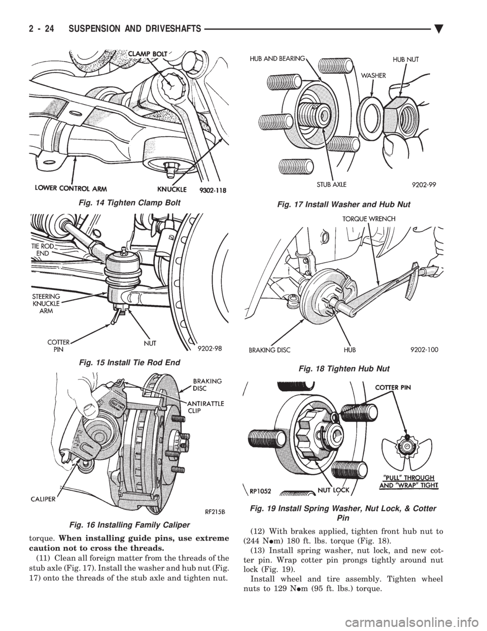
torque. When installing guide pins, use extreme
caution not to cross the threads. (11) Clean all foreign matter from the threads of the
stub axle (Fig. 17). Install the washer and hub nut (Fig.
17) onto the threads of the stub axle and tighten nut. (12) With brakes applied, tighten front hub nut to
(244 N Im) 180 ft. lbs. torque (Fig. 18).
(13) Install spring washer, nut lock, and new cot-
ter pin. Wrap cotter pin prongs tightly around nut
lock (Fig. 19). Install wheel and tire assembly. Tighten wheel
nuts to 129 N Im (95 ft. lbs.) torque.
Fig. 15 Install Tie Rod End
Fig. 16 Installing Family Caliper
Fig. 17 Install Washer and Hub Nut
Fig. 18 Tighten Hub Nut
Fig. 19 Install Spring Washer, Nut Lock, & Cotter
Pin
Fig. 14 Tighten Clamp Bolt
2 - 24 SUSPENSION AND DRIVESHAFTS Ä
Page 85 of 2438
DRIVESHAFT IDENTIFICATION
Driveshafts are identified by the manufacturer. Vehi-
cles can be equipped with any of these driveshaft as-
semblies. Each assembly can be identified as shown in
(Fig. 2).
SERVICE PROCEDURES
Procedures for the removal and installation of the
driveshafts are essentially the same for all front
wheel drive vehicles. Each driveshaft has a spring
within the inboard Tripod C/V joint that maintains
constant engagement with the transaxle. This allows
the drive shaft to be removed without dismantling
part of the transaxle.
CAUTION: Boot sealing is vital to retain special lu-
bricants and to prevent foreign contaminants from
entering the C/V joint. Mishandling, such as allow-
ing the assemblies to dangle unsupported, pulling
or pushing the ends can cut boots or damage C/V
joints. During removal and installation procedures
always support both ends of the driveshaft to pre-
vent damage.
DRIVESHAFTS, REMOVE INSTALL
HUB NUT REMOVAL
Hub nut removal and installation is the same for
all front wheel drive vehicles. For installation see
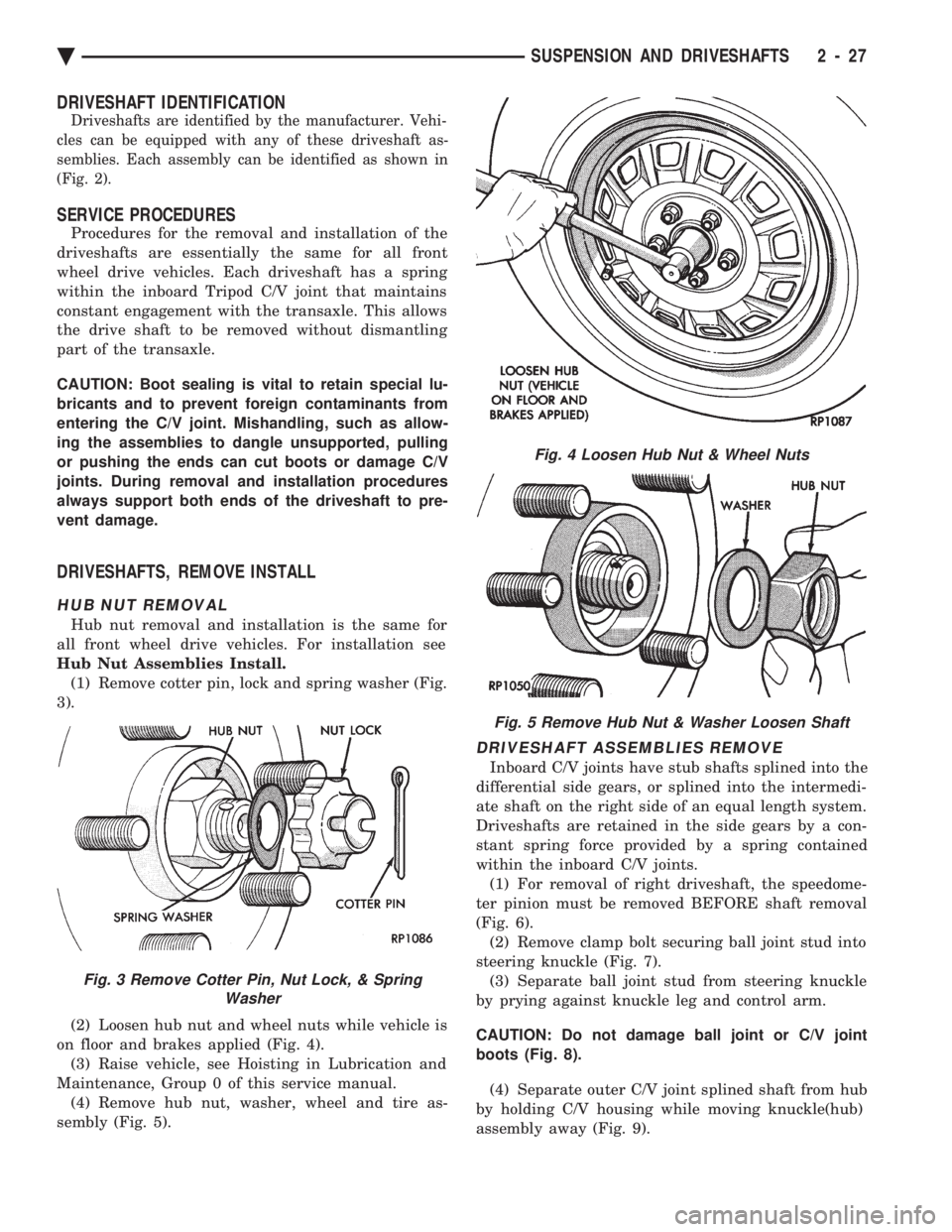
Hub Nut Assemblies Install. (1) Remove cotter pin, lock and spring washer (Fig.
3).
(2) Loosen hub nut and wheel nuts while vehicle is
on floor and brakes applied (Fig. 4). (3) Raise vehicle, see Hoisting in Lubrication and
Maintenance, Group 0 of this service manual. (4) Remove hub nut, washer, wheel and tire as-
sembly (Fig. 5).
DRIVESHAFT ASSEMBLIES REMOVE
Inboard C/V joints have stub shafts splined into the
differential side gears, or splined into the intermedi-
ate shaft on the right side of an equal length system.
Driveshafts are retained in the side gears by a con-
stant spring force provided by a spring contained
within the inboard C/V joints. (1) For removal of right driveshaft, the speedome-
ter pinion must be removed BEFORE shaft removal
(Fig. 6). (2) Remove clamp bolt securing ball joint stud into
steering knuckle (Fig. 7). (3) Separate ball joint stud from steering knuckle
by prying against knuckle leg and control arm.
CAUTION: Do not damage ball joint or C/V joint
boots (Fig. 8). (4) Separate outer C/V joint splined shaft from hub
by holding C/V housing while moving knuckle(hub)
assembly away (Fig. 9).
Fig. 3 Remove Cotter Pin, Nut Lock, & Spring Washer
Fig. 4 Loosen Hub Nut & Wheel Nuts
Fig. 5 Remove Hub Nut & Washer Loosen Shaft
Ä SUSPENSION AND DRIVESHAFTS 2 - 27
Page 88 of 2438
not to allow dirt to enter or grease to leave the boot
cavity. The clamp must be removed and discarded be-
fore the rod can be inserted. After venting, install a
new Service Clamp. (See Boots Install section at the
end of this group for details).
HUB NUT INSTALL
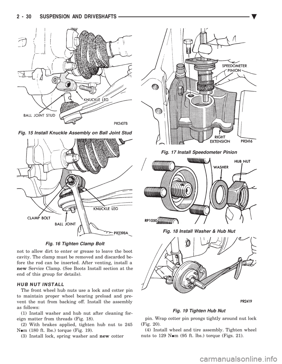
The front wheel hub nuts use a lock and cotter pin
to maintain proper wheel bearing preload and pre-
vent the nut from backing off. Install the assembly
as follows: (1) Install washer and hub nut after cleaning for-
eign matter from threads (Fig. 18). (2) With brakes applied, tighten hub nut to 245
N Im (180 ft. lbs.) torque (Fig. 19).
(3) Install lock, spring washer and newcotter pin. Wrap cotter pin prongs tightly around nut lock
(Fig. 20). (4) Install wheel and tire assembly. Tighten wheel
nuts to 129 N Im (95 ft. lbs.) torque (Figs. 21).
Fig. 15 Install Knuckle Assembly on Ball Joint Stud
Fig. 16 Tighten Clamp Bolt
Fig. 17 Install Speedometer Pinion
Fig. 18 Install Washer & Hub Nut
Fig. 19 Tighten Hub Nut
2 - 30 SUSPENSION AND DRIVESHAFTS Ä
Page 109 of 2438
to the road surface. While being able to twist as one
wheel moves vertically with respect to the other.Roll resistance is provided partly by the axle's re-
sistance to twist. But primarily by a torque tube or
rod (depending on the suspension option called for)
running through the channel and attached rigidly to
its end plates by welding. Because the torque tube/
rod is an integral part of the axle assembly, it cannot
be individually replaced. The spindles are bolted to the axle end (spindle
mounting) plates and can be individually replaced if
required. Rear wheel alignment changes require the
use of shims between the spindle and axle end plates.
SHOCK ABSORBERS
REMOVAL
(1) Raise vehicle, see Hoisting, Group 0.
(2) Support axle and remove wheel and tire assem-
bly. (3) If equipped with air shocks, disconnect air
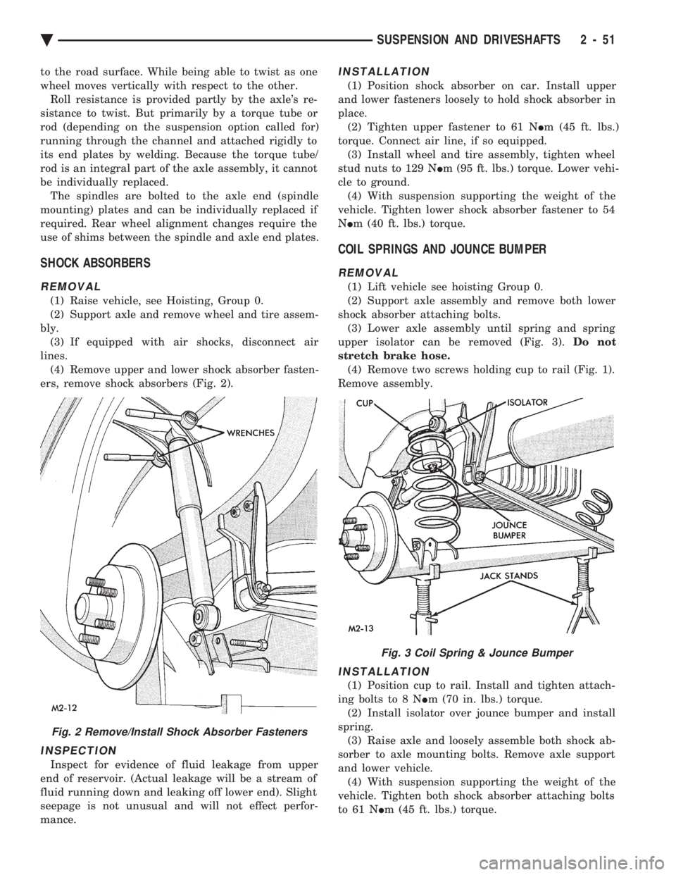
lines. (4) Remove upper and lower shock absorber fasten-
ers, remove shock absorbers (Fig. 2).
INSPECTION
Inspect for evidence of fluid leakage from upper
end of reservoir. (Actual leakage will be a stream of
fluid running down and leaking off lower end). Slight
seepage is not unusual and will not effect perfor-
mance.
INSTALLATION
(1) Position shock absorber on car. Install upper
and lower fasteners loosely to hold shock absorber in
place. (2) Tighten upper fastener to 61 N Im (45 ft. lbs.)
torque. Connect air line, if so equipped. (3) Install wheel and tire assembly, tighten wheel
stud nuts to 129 N Im (95 ft. lbs.) torque. Lower vehi-
cle to ground. (4) With suspension supporting the weight of the
vehicle. Tighten lower shock absorber fastener to 54
N Im (40 ft. lbs.) torque.
COIL SPRINGS AND JOUNCE BUMPER
REMOVAL
(1) Lift vehicle see hoisting Group 0.
(2) Support axle assembly and remove both lower
shock absorber attaching bolts. (3) Lower axle assembly until spring and spring
upper isolator can be removed (Fig. 3). Do not
stretch brake hose. (4) Remove two screws holding cup to rail (Fig. 1).
Remove assembly.
INSTALLATION
(1) Position cup to rail. Install and tighten attach-
ing bolts to 8 N Im (70 in. lbs.) torque.
(2) Install isolator over jounce bumper and install
spring. (3) Raise axle and loosely assemble both shock ab-
sorber to axle mounting bolts. Remove axle support
and lower vehicle. (4) With suspension supporting the weight of the
vehicle. Tighten both shock absorber attaching bolts
to 61 N Im (45 ft. lbs.) torque.
Fig. 2 Remove/Install Shock Absorber Fasteners
Fig. 3 Coil Spring & Jounce Bumper
Ä SUSPENSION AND DRIVESHAFTS 2 - 51
Page 110 of 2438
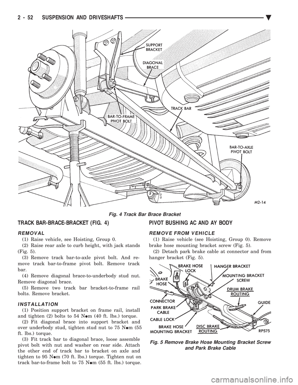
TRACK BAR-BRACE-BRACKET (FIG. 4)
REMOVAL
(1) Raise vehicle, see Hoisting, Group 0.
(2) Raise rear axle to curb height, with jack stands
(Fig. 5). (3) Remove track bar-to-axle pivot bolt. And re-
move track bar-to-frame pivot bolt. Remove track
bar. (4) Remove diagonal brace-to-underbody stud nut.
Remove diagonal brace. (5) Remove two track bar bracket-to-frame rail
bolts. Remove bracket.
INSTALLATION
(1) Position support bracket on frame rail, install
and tighten (2) bolts to 54 N Im (40 ft. lbs.) torque.
(2) Fit diagonal brace into support bracket and
over underbody stud, tighten stud nut to 75 N Im (55
ft. lbs.) torque. (3) Fit track bar to diagonal brace, loose assemble
pivot bolt with nut and washer on rear side. Attach
the other end of track bar to bracket on axle and
tighten to 95 N Im (70 ft. lbs.) torque. Tighten nut on
track bar-to-frame bolt to 75 N Im (55 ft. lbs.) torque.
PIVOT BUSHING AC AND AY BODY
REMOVE FROM VEHICLE
(1) Raise vehicle (see Hoisting, Group 0). Remove
brake hose mounting bracket screw (Fig. 5). (2) Detach park brake cable at connector and from
hanger bracket (Fig. 5).
Fig. 4 Track Bar Brace Bracket
Fig. 5 Remove Brake Hose Mounting Bracket Screw and Park Brake Cable
2 - 52 SUSPENSION AND DRIVESHAFTS Ä