air bleeding CHEVROLET DYNASTY 1993 Service Manual
[x] Cancel search | Manufacturer: CHEVROLET, Model Year: 1993, Model line: DYNASTY, Model: CHEVROLET DYNASTY 1993Pages: 2438, PDF Size: 74.98 MB
Page 156 of 2438
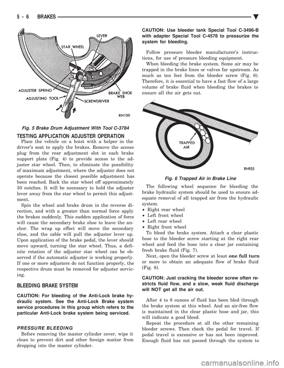
TESTING APPLICATION ADJUSTER OPERATION
Place the vehicle on a hoist with a helper in the
driver's seat to apply the brakes. Remove the access
plug from the rear adjustment slot in each brake
support plate (Fig. 4) to provide access to the ad-
juster star wheel. Then, to eliminate the possibility
of maximum adjustment, where the adjuster does not
operate because the closest possible adjustment has
been reached. Back the star wheel off approximately
30 notches. It will be necessary to hold the adjuster
lever away from the star wheel to permit this adjust-
ment. Spin the wheel and brake drum in the reverse di-
rection, and with a greater than normal force apply
the brakes suddenly. This sudden application of force
will cause the secondary brake shoe to leave the an-
chor. The wrap up effect will move the secondary
shoe, and the cable will pull the adjuster lever up.
Upon application of the brake pedal, the lever should
move upward, turning the star wheel. Thus, a defi-
nite rotation of the adjuster star wheel can be ob-
served if the automatic adjuster is working properly.
If one or more adjusters do not function properly, the
respective drum must be removed for adjuster servic-
ing.
BLEEDING BRAKE SYSTEM
CAUTION: For bleeding of the Anti-Lock brake hy-
draulic system. See the Anti-Lock Brake system
service procedures in this group which refers to the
particular Anti-Lock brake system being serviced.
PRESSURE BLEEDING
Before removing the master cylinder cover, wipe it
clean to prevent dirt and other foreign matter from
dropping into the master cylinder. CAUTION: Use bleeder tank Special Tool C-3496-B
with adapter Special Tool C-4578 to pressurize the
system for bleeding.
Follow pressure bleeder manufacturer's instruc-
tions, for use of pressure bleeding equipment. When bleeding the brake system. Some air may be
trapped in the brake lines or valves far upstream. As
much as ten feet from the bleeder screw (Fig. 6).
Therefore, it is essential to have a fast flow of a large
volume of brake fluid when bleeding the brakes to
ensure all the air gets out.
The following wheel sequence for bleeding the
brake hydraulic system should be used to ensure ad-
equate removal of all trapped air from the hydraulic
system.
² Right rear wheel
² Left front wheel
² Left rear wheel
² Right front wheel
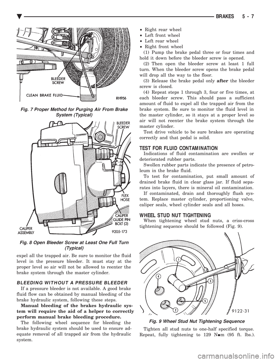
To bleed the brake system. Attach a clear plastic
hose to the bleeder screw starting at the right rear
wheel and feed the hose into a clear jar containing
fresh brake fluid (Fig. 7). Next, open the bleeder screw at least one full turn
or more to obtain an adequate flow of brake fluid
(Fig. 8).
CAUTION: Just cracking the bleeder screw often re-
stricts fluid flow, and a slow, weak fluid discharge
will NOT get all the air out.
After 4 to 8 ounces of fluid has been bled through
the brake system at this wheel. And an air-free flow
is maintained in the clear plastic hose and jar, this
will indicate a good bleed. Repeat the procedure at all the other remaining
bleeder screws. Then check the pedal for travel. If
pedal travel is excessive or has not been improved.
Enough fluid has not passed through the system to
Fig. 5 Brake Drum Adjustment With Tool C-3784
Fig. 6 Trapped Air in Brake Line
5 - 6 BRAKES Ä
Page 157 of 2438
expel all the trapped air. Be sure to monitor the fluid
level in the pressure bleeder. It must stay at the
proper level so air will not be allowed to reenter the
brake system through the master cylinder.
BLEEDING WITHOUT A PRESSURE BLEEDER
If a pressure bleeder is not available. A good brake
fluid flow can be obtained by manual bleeding of the
brake hydraulic system, following these steps. Manual bleeding of the brakes hydraulic sys-
tem will require the aid of a helper to correctly
perform manual brake bleeding procedure. The following wheel sequence for bleeding the
brake hydraulic system should be used to ensure ad-
equate removal of all trapped air from the hydraulic
system. ²
Right rear wheel
² Left front wheel
² Left rear wheel
² Right front wheel
(1) Pump the brake pedal three or four times and
hold it down before the bleeder screw is opened. (2) Then open the bleeder screw at least 1 full
turn. When the bleeder screw opens the brake pedal
will drop all the way to the floor. (3) Release the brake pedal only afterthe bleeder
screw is closed. (4) Repeat steps 1 through 3, four or five times, at
each bleeder screw. This should pass a sufficient
amount of fluid to expel all the trapped air from the
brake system. Be sure to monitor the fluid level in
the master cylinder, so it stays at a proper level so
air will not reenter the brake system through the
master cylinder. Test drive vehicle to be sure brakes are operating
correctly and that pedal is solid.
TEST FOR FLUID CONTAMINATION
Indications of fluid contamination are swollen or
deteriorated rubber parts. Swollen rubber parts indicate the presence of petro-
leum in the brake fluid. To test for contamination, put small amount of
drained brake fluid in clear glass jar. If fluid sepa-
rates into layers, there is mineral oil contamination. If contaminated, drain and thoroughly flush sys-
tem. Replace master cylinder, proportioning valve,
caliper seals, wheel cylinder seals and all hoses.
WHEEL STUD NUT TIGHTENING
When tightening wheel stud nuts, a criss-cross
tightening sequence should be followed (Fig. 9).
Tighten all stud nuts to one-half specified torque.
Repeat, fully tightening to 129 N Im (95 ft. lbs.).
Fig. 9 Wheel Stud Nut Tightening Sequence
Fig. 7 Proper Method for Purging Air From Brake
System (Typical)
Fig. 8 Open Bleeder Screw at Least One Full Turn (Typical)
Ä BRAKES 5 - 7
Page 174 of 2438
cylinder bore and piston for scoring and pitting. (Do
not use a rag as lint from the rag will stick to bore
surfaces.) Wheel cylinder bores and pistons that are scored or
pitted in any way should be replaced. Cylinder walls
that have light scratches, or show signs of corrosion,
can usually be cleaned with crocus cloth, using a cir-
cular motion. Black stains on the cylinder walls are
caused by piston cups and will not impair operation
of cylinder.
ASSEMBLING WHEEL CYLINDERS
Before assembling the pistons and new cups in the
wheel cylinders, dip them in clean brake fluid. If the
boots are deteriorated, cracked or do not fit tightly
on the pistons or the cylinder casting, install new
boots. (1) Coat cylinder bore with clean brake fluid.
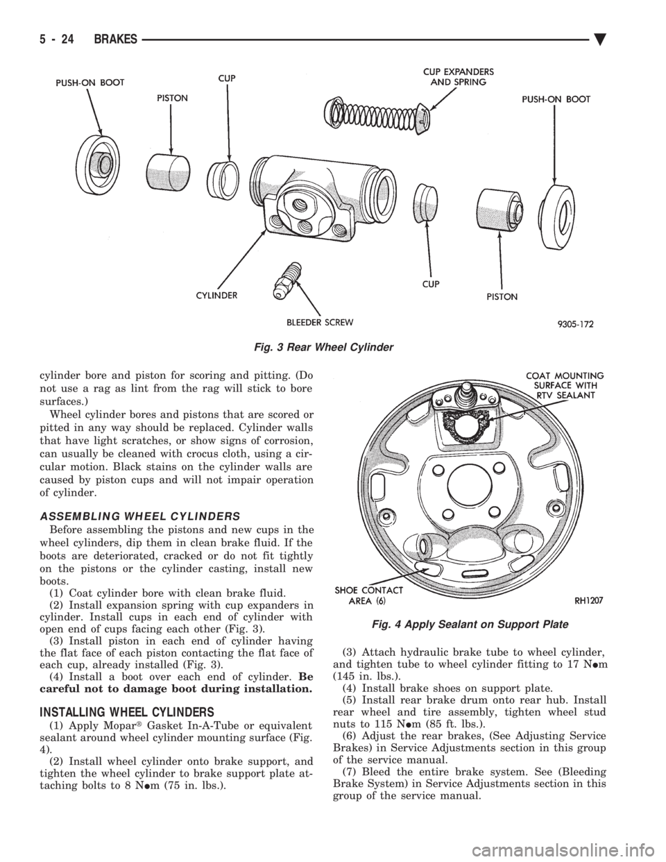
(2) Install expansion spring with cup expanders in
cylinder. Install cups in each end of cylinder with
open end of cups facing each other (Fig. 3). (3) Install piston in each end of cylinder having
the flat face of each piston contacting the flat face of
each cup, already installed (Fig. 3). (4) Install a boot over each end of cylinder. Be
careful not to damage boot during installation.
INSTALLING WHEEL CYLINDERS
(1) Apply Mopar tGasket In-A-Tube or equivalent
sealant around wheel cylinder mounting surface (Fig.
4). (2) Install wheel cylinder onto brake support, and
tighten the wheel cylinder to brake support plate at-
taching bolts to 8 N Im (75 in. lbs.). (3) Attach hydraulic brake tube to wheel cylinder,
and tighten tube to wheel cylinder fitting to 17 N Im
(145 in. lbs.). (4) Install brake shoes on support plate.
(5) Install rear brake drum onto rear hub. Install
rear wheel and tire assembly, tighten wheel stud
nuts to 115 N Im (85 ft. lbs.).
(6) Adjust the rear brakes, (See Adjusting Service
Brakes) in Service Adjustments section in this group
of the service manual. (7) Bleed the entire brake system. See (Bleeding
Brake System) in Service Adjustments section in this
group of the service manual.
Fig. 3 Rear Wheel Cylinder
Fig. 4 Apply Sealant on Support Plate
5 - 24 BRAKES Ä
Page 177 of 2438
to the rear will be lower than the front brakes. This will
prevent premature rear wheel lock-up and skid. If
hydraulic pressure is lost in one half of the diagonally
split system, the operation of the proportioning valve
in the remaining half is not effected.
ABS BRAKE PROPORTIONING VALVE OPERATION
On vehicles using the ABS braking system, screw in
proportioning valves are used in place of the conven-
tional differential pressure/proportioning valve. Each rear brake circuit has its own screw-in propor-
tioning valve which is attached to the rear brake outlet
ports of the hydraulic assembly. These valves limit
brake pressure to the rear brakes after a certain
pressure is reached. This improves front to rear brake
balance during normal braking.
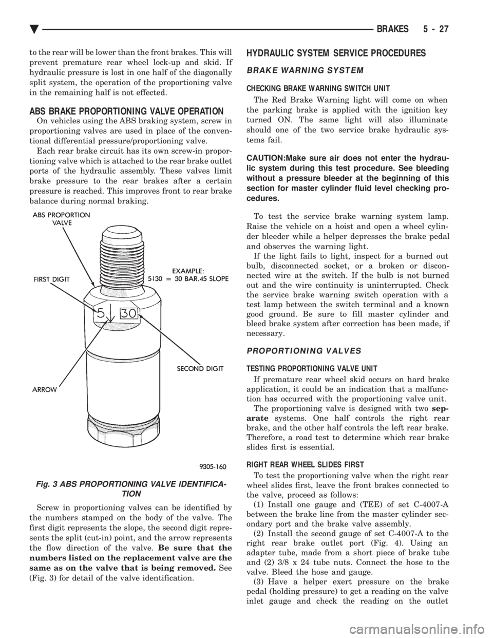
Screw in proportioning valves can be identified by
the numbers stamped on the body of the valve. The
first digit represents the slope, the second digit repre-
sents the split (cut-in) point, and the arrow represents
the flow direction of the valve. Be sure that the
numbers listed on the replacement valve are the
same as on the valve that is being removed. See
(Fig. 3) for detail of the valve identification.
HYDRAULIC SYSTEM SERVICE PROCEDURES
BRAKE WARNING SYSTEM
CHECKING BRAKE WARNING SWITCH UNIT
The Red Brake Warning light will come on when
the parking brake is applied with the ignition key
turned ON. The same light will also illuminate
should one of the two service brake hydraulic sys-
tems fail.
CAUTION:Make sure air does not enter the hydrau-
lic system during this test procedure. See bleeding
without a pressure bleeder at the beginning of this
section for master cylinder fluid level checking pro-
cedures.
To test the service brake warning system lamp.
Raise the vehicle on a hoist and open a wheel cylin-
der bleeder while a helper depresses the brake pedal
and observes the warning light. If the light fails to light, inspect for a burned out
bulb, disconnected socket, or a broken or discon-
nected wire at the switch. If the bulb is not burned
out and the wire continuity is uninterrupted. Check
the service brake warning switch operation with a
test lamp between the switch terminal and a known
good ground. Be sure to fill master cylinder and
bleed brake system after correction has been made, if
necessary.
PROPORTIONING VALVES
TESTING PROPORTIONING VALVE UNIT
If premature rear wheel skid occurs on hard brake
application, it could be an indication that a malfunc-
tion has occurred with the proportioning valve unit. The proportioning valve is designed with two sep-
arate systems. One half controls the right rear
brake, and the other half controls the left rear brake.
Therefore, a road test to determine which rear brake
slides first is essential.
RIGHT REAR WHEEL SLIDES FIRST To test the proportioning valve when the right rear
wheel slides first, leave the front brakes connected to
the valve, proceed as follows: (1) Install one gauge and (TEE) of set C-4007-A
between the brake line from the master cylinder sec-
ondary port and the brake valve assembly. (2) Install the second gauge of set C-4007-A to the
right rear brake outlet port (Fig. 4). Using an
adapter tube, made from a short piece of brake tube
and (2) 3/8 x 24 tube nuts. Connect the hose to the
valve. Bleed the hose and gauge. (3) Have a helper exert pressure on the brake
pedal (holding pressure) to get a reading on the valve
inlet gauge and check the reading on the outlet
Fig. 3 ABS PROPORTIONING VALVE IDENTIFICA- TION
Ä BRAKES 5 - 27
Page 217 of 2438
MASTER CYLINDER SERVICE PROCEDURES
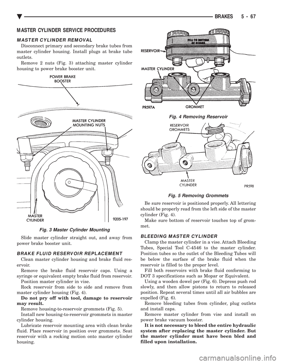
MASTER CYLINDER REMOVAL
Disconnect primary and secondary brake tubes from
master cylinder housing. Install plugs at brake tube
outlets. Remove 2 nuts (Fig. 3) attaching master cylinder
housing to power brake booster unit.
Slide master cylinder straight out, and away from
power brake booster unit.
BRAKE FLUID RESERVOIR REPLACEMENT
Clean master cylinder housing and brake fluid res-
ervoir. Remove the brake fluid reservoir caps. Using a
syringe or equivalent empty brake fluid from reservoir. Position master cylinder in vise.
Rock reservoir from side to side and remove from
master cylinder housing (Fig. 4). Do not pry off with tool, damage to reservoir
may result. Remove housing-to-reservoir grommets (Fig. 5).
Install new housing-to-reservoir grommets in master
cylinder housing. Lubricate reservoir mounting area with clean brake
fluid. Place reservoir in position over grommets. Seat
reservoir with a rocking motion onto master cylinder
housing. Be sure reservoir is positioned properly. All lettering
should be properly read from the left side of the master
cylinder (Fig. 4). Make sure bottom of reservoir touches top of grom-
met.
BLEEDING MASTER CYLINDER
Clamp the master cylinder in a vise. Attach Bleeding
Tubes, Special Tool C-4546 to the master cylinder.
Position tubes so the outlet of the Bleeding Tubes will
be below the surface of the brake fluid when the
reservoir is filled to the proper level. Fill both reservoirs with brake fluid conforming to
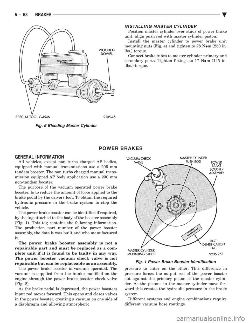
DOT 3 specifications such as Mopar or Equivalent. Using a wooden dowel per (Fig. 6). Depress push rod
slowly, and then allow pistons to return to released
position. Repeat several times until all air bubbles are
expelled (Fig. 6). Remove bleeding tubes from cylinder, plug outlets
and install caps. Remove master cylinder from vise and install on
power brake vacuum booster. It is not necessary to bleed the entire hydraulic
system after replacing the master cylinder. But
the master cylinder must have been bled and
filled upon installation.
Fig. 4 Removing Reservoir
Fig. 5 Removing Grommets
Fig. 3 Master Cylinder Mounting
Ä BRAKES 5 - 67
Page 218 of 2438
INSTALLING MASTER CYLINDER
Position master cylinder over studs of power brake
unit, align push rod with master cylinder piston. Install the master cylinder to power brake unit
mounting nuts (Fig. 4) and tighten to 28 N Im (250 in.
lbs.) torque. Connect brake tubes to master cylinder primary and
secondary ports. Tighten fittings to 17 N Im (145 in-
.lbs.) torque.
POWER BRAKES
GENERAL INFORMATION
All vehicles, except non turbo charged AP bodies,
equipped with manual transmissions use a 205 mm
tandem booster. The non turbo charged manual trans-
mission equipped AP body application use a 230 mm
non-tandem booster. The purpose of the vacuum operated power brake
booster. Is to reduce the amount of force applied to the
brake pedal by the drivers foot. To obtain the required
hydraulic pressure in the brake system to stop the
vehicle. The power brake booster can be identified if required,
by the tag attached to the body of the booster assembly
(Fig. 1). This tag contains the following information.
The production part number of the power booster
assembly, the date it was built and who manufactured
it. The power brake booster assembly is not a
repairable part and must be replaced as a com-
plete unit if it is found to be faulty in any way.
The power booster vacuum check valve is not
repairable but can be replaceable as an assembly. The power brake booster is vacuum operated. The
vacuum is supplied from the intake manifold on the
engine through the power brake booster check valve
(Fig. 2). As the brake pedal is depressed, the power boosters
input rod moves forward. This opens and closes valves
in the power booster, creating a vacuum on one side of
a diaphragm and allowing atmospheric pressure to enter on the other. This difference in
pressure forces the output rod of the power booster
out against the primary piston of the master cylin-
der. As the pistons in the master cylinder move for-
ward this creates the hydraulic pressure in the brake
system. Different systems and engine combinations require
different vacuum hose routings.
Fig. 6 Bleeding Master Cylinder
Fig. 1 Power Brake Booster Identification
5 - 68 BRAKES Ä
Page 244 of 2438
pressurized. When a definite increase in pedal effort
is felt, pump pedal a few additional times. This will
insure removal of all hydraulic pressure from the
brake system.(2) Thoroughly clean both reservoir caps and sur-
rounding area of reservoir before cap removal. This
will avoid getting dirt into the reservoir and brake
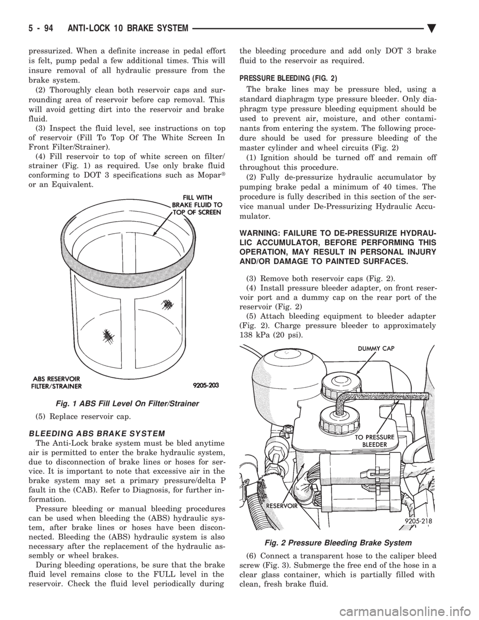
fluid. (3) Inspect the fluid level, see instructions on top
of reservoir (Fill To Top Of The White Screen In
Front Filter/Strainer). (4) Fill reservoir to top of white screen on filter/
strainer (Fig. 1) as required. Use only brake fluid
conforming to DOT 3 specifications such as Mopar t
or an Equivalent.
(5) Replace reservoir cap.
BLEEDING ABS BRAKE SYSTEM
The Anti-Lock brake system must be bled anytime
air is permitted to enter the brake hydraulic system,
due to disconnection of brake lines or hoses for ser-
vice. It is important to note that excessive air in the
brake system may set a primary pressure/delta P
fault in the (CAB). Refer to Diagnosis, for further in-
formation. Pressure bleeding or manual bleeding procedures
can be used when bleeding the (ABS) hydraulic sys-
tem, after brake lines or hoses have been discon-
nected. Bleeding the (ABS) hydraulic system is also
necessary after the replacement of the hydraulic as-
sembly or wheel brakes. During bleeding operations, be sure that the brake
fluid level remains close to the FULL level in the
reservoir. Check the fluid level periodically during the bleeding procedure and add only DOT 3 brake
fluid to the reservoir as required.
PRESSURE BLEEDING (FIG. 2)
The brake lines may be pressure bled, using a
standard diaphragm type pressure bleeder. Only dia-
phragm type pressure bleeding equipment should be
used to prevent air, moisture, and other contami-
nants from entering the system. The following proce-
dure should be used for pressure bleeding of the
master cylinder and wheel circuits (Fig. 2) (1) Ignition should be turned off and remain off
throughout this procedure. (2) Fully de-pressurize hydraulic accumulator by
pumping brake pedal a minimum of 40 times. The
procedure is fully described in this section of the ser-
vice manual under De-Pressurizing Hydraulic Accu-
mulator.
WARNING: FAILURE TO DE-PRESSURIZE HYDRAU-
LIC ACCUMULATOR, BEFORE PERFORMING THIS
OPERATION, MAY RESULT IN PERSONAL INJURY
AND/OR DAMAGE TO PAINTED SURFACES.
(3) Remove both reservoir caps (Fig. 2).
(4) Install pressure bleeder adapter, on front reser-
voir port and a dummy cap on the rear port of the
reservoir (Fig. 2) (5) Attach bleeding equipment to bleeder adapter
(Fig. 2). Charge pressure bleeder to approximately
138 kPa (20 psi).
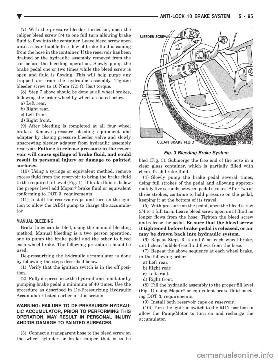
(6) Connect a transparent hose to the caliper bleed
screw (Fig. 3). Submerge the free end of the hose in a
clear glass container, which is partially filled with
clean, fresh brake fluid.
Fig. 1 ABS Fill Level On Filter/Strainer
Fig. 2 Pressure Bleeding Brake System
5 - 94 ANTI-LOCK 10 BRAKE SYSTEM Ä
Page 245 of 2438
(7) With the pressure bleeder turned on, open the
caliper bleed screw 3/4 to one full turn allowing brake
fluid to flow into the container. Leave bleed screw open
until a clear, bubble-free flow of brake fluid is coming
from the hose in the container. If the reservoir has been
drained or the hydraulic assembly removed from the
car before the bleeding operation. Slowly pump the
brake pedal one or two times while the bleed screw is
open and fluid is flowing. This will help purge any
trapped air from the hydraulic assembly. Tighten
bleeder screw to 10 N Im (7.5 ft. lbs.) torque.
(8) Step 7 above should be done at all wheel brakes,
following the order wheel by wheel as listed below. a) Left rear.
b) Right rear.
c) Left front.
d) Right front.
(9) After bleeding is completed at all four wheel
brakes. Remove pressure bleeding equipment and
adapter by closing pressure bleeder valve and slowly
unscrewing bleeder adapter from hydraulic assembly
reservoir. Failure to release pressure in the reser-
voir will cause spillage of brake fluid, and could
result in personal injury or damage to painted
surfaces. (10) Using a syringe or equivalent method, remove
excess fluid from the reservoir to bring the brake fluid
to the required fill level (Fig. 1). If brake fluid is below
the proper level add Mopar tbrake fluid or equivalent
conforming to DOT 3, requirements. (11) Install the reservoir caps and turn on the igni-
tion to allow the (ABS) pump to charge the accumula-
tor.
MANUAL BLEEDING
Brake lines can be bled, using the manual bleeding
method. Manual bleeding is a two person operation,
one to pump the brake pedal and the other to bleed
each wheel brake. The following procedure should be
used: De-pressurizing the hydraulic accumulator is done
by following the steps described below. (1) Verify that the ignition switch is in the off posi-
tion. (2) Fully de-pressurize the hydraulic accumulator by
pumping brake pedal a minimum of 40 times. Use the
procedure as described in De-Pressurizing Hydraulic
Accumulator listed earlier in this section.
WARNING: FAILURE TO DE-PRESSURIZE HYDRAU-
LIC ACCUMULATOR, PRIOR TO PERFORMING THIS
OPERATION, MAY RESULT IN PERSONAL INJURY
AND/OR DAMAGE TO PAINTED SURFACES.
(3) Connect a transparent hose to the bleed screw on
the wheel cylinder or brake caliper that is to be bled (Fig. 3). Submerge the free end of the hose in a
clear glass container, which is partially filled with
clean, fresh brake fluid.
(4) Slowly pump the brake pedal several times,
using full strokes of the pedal and allowing approxi-
mately five seconds between pedal strokes. After two or
three strokes, continue to hold pressure on the pedal,
keeping it at the bottom of its travel. (5) With pressure on the pedal, open the bleed screw
3/4 to 1 full turn. Leave bleed screw open until fluid no
longer flows from the hose. Tighten the bleed screw
and release the pedal. Be sure that the bleed screw
it tightened before brake pedal is released, or air
may be drawn back into hydraulic system. (6) Repeat Steps 3, 4 and 5 on each wheel brake,
until clear, bubble-free fluid flows from the hose. (7) Repeat the above sequence at each wheel brake,
in the following order: a) Left rear.
b) Right rear.
c) Left front.
d) Right front.
(8) Fill the hydraulic assembly to the proper fill level
(Fig. 1) using Mopar tor equivalent brake fluid meet-
ing DOT 3, requirements. (9) Install both reservoir caps on reservoir.
(10) Turn the ignition switch to the RUN position to
allow the Pump/Motor to turn on and recharge the
accumulator.
Fig. 3 Bleeding Brake System
Ä ANTI-LOCK 10 BRAKE SYSTEM 5 - 95
Page 246 of 2438
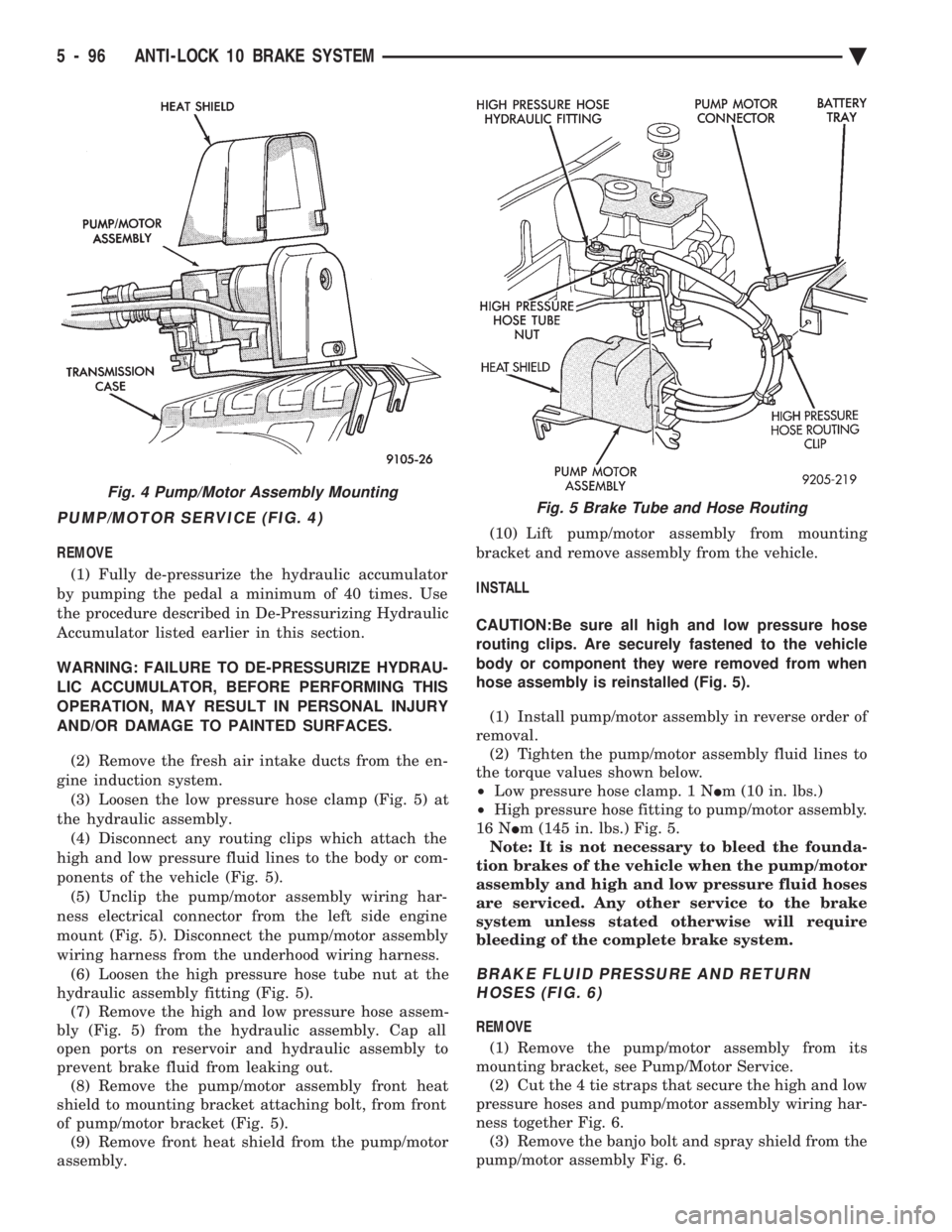
PUMP/MOTOR SERVICE (FIG. 4)
REMOVE (1) Fully de-pressurize the hydraulic accumulator
by pumping the pedal a minimum of 40 times. Use
the procedure described in De-Pressurizing Hydraulic
Accumulator listed earlier in this section.
WARNING: FAILURE TO DE-PRESSURIZE HYDRAU-
LIC ACCUMULATOR, BEFORE PERFORMING THIS
OPERATION, MAY RESULT IN PERSONAL INJURY
AND/OR DAMAGE TO PAINTED SURFACES.
(2) Remove the fresh air intake ducts from the en-
gine induction system. (3) Loosen the low pressure hose clamp (Fig. 5) at
the hydraulic assembly. (4) Disconnect any routing clips which attach the
high and low pressure fluid lines to the body or com-
ponents of the vehicle (Fig. 5). (5) Unclip the pump/motor assembly wiring har-
ness electrical connector from the left side engine
mount (Fig. 5). Disconnect the pump/motor assembly
wiring harness from the underhood wiring harness. (6) Loosen the high pressure hose tube nut at the
hydraulic assembly fitting (Fig. 5). (7) Remove the high and low pressure hose assem-
bly (Fig. 5) from the hydraulic assembly. Cap all
open ports on reservoir and hydraulic assembly to
prevent brake fluid from leaking out. (8) Remove the pump/motor assembly front heat
shield to mounting bracket attaching bolt, from front
of pump/motor bracket (Fig. 5). (9) Remove front heat shield from the pump/motor
assembly. (10) Lift pump/motor assembly from mounting
bracket and remove assembly from the vehicle.
INSTALL
CAUTION:Be sure all high and low pressure hose
routing clips. Are securely fastened to the vehicle
body or component they were removed from when
hose assembly is reinstalled (Fig. 5).
(1) Install pump/motor assembly in reverse order of
removal. (2) Tighten the pump/motor assembly fluid lines to
the torque values shown below.
² Low pressure hose clamp. 1 N Im (10 in. lbs.)
² High pressure hose fitting to pump/motor assembly.
16 N Im (145 in. lbs.) Fig. 5.
Note: It is not necessary to bleed the founda-
tion brakes of the vehicle when the pump/motor
assembly and high and low pressure fluid hoses
are serviced. Any other service to the brake
system unless stated otherwise will require
bleeding of the complete brake system.
BRAKE FLUID PRESSURE AND RETURN HOSES (FIG. 6)
REMOVE
(1) Remove the pump/motor assembly from its
mounting bracket, see Pump/Motor Service. (2) Cut the 4 tie straps that secure the high and low
pressure hoses and pump/motor assembly wiring har-
ness together Fig. 6. (3) Remove the banjo bolt and spray shield from the
pump/motor assembly Fig. 6.
Fig. 4 Pump/Motor Assembly MountingFig. 5 Brake Tube and Hose Routing
5 - 96 ANTI-LOCK 10 BRAKE SYSTEM Ä
Page 249 of 2438
(7) Install high pressure hose to hydraulic assem-
bly (Fig. 7). Tighten the hose, to hydraulic assembly
fitting to 16 N Im (145 in. lbs)
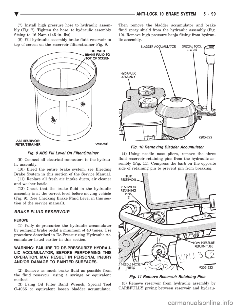
(8) Fill hydraulic assembly brake fluid reservoir to
top of screen on the reservoir filter/strainer Fig. 9.
(9) Connect all electrical connectors to the hydrau-
lic assembly. (10) Bleed the entire brake system, see Bleeding
Brake System in this section of the Service Manual. (11) Replace all fresh air intake ducts, air cleaner
and washer bottle. (12) Check that the brake fluid in the hydraulic
assembly is at the correct level before moving vehicle
(Fig. 9). (See Checking Brake Fluid Level in this sec-
tion of the service manual).
BRAKE FLUID RESERVOIR
REMOVE
(1) Fully de-pressurize the hydraulic accumulator
by pumping brake pedal a minimum of 40 times. Use
procedure described in De-Pressurizing Hydraulic Ac-
cumulator listed earlier in this section.
WARNING: FAILURE TO DE-PRESSURIZE HYDRAU-
LIC ACCUMULATOR, BEFORE PERFORMING THIS
OPERATION, MAY RESULT IN PERSONAL INJURY
AND/OR DAMAGE TO PAINTED SURFACES.
(2) Remove as much brake fluid as possible from
the fluid reservoir, using a syringe or equivalent
method. (3) Using Oil Filter Band Wrench, Special Tool
C-4065 or equivalent loosen bladder accumulator. Then remove the bladder accumulator and brake
fluid spray shield from the hydraulic assembly (Fig.
10). Remove high pressure banjo fitting from hydrau-
lic assembly.
(4) Using needle nose pliers, remove the three
fluid reservoir retaining pins from the hydraulic as-
sembly (Fig. 11). Compress the barb on the opposite
side of retaining pin to prevent pin from breaking.
(5) Remove reservoir from hydraulic assembly by
CAREFULLY prying between reservoir and hydrau-
Fig. 9 ABS Fill Level On Filter/Strainer
Fig. 10 Removing Bladder Accumulator
Fig. 11 Remove Reservoir Retaining Pins
Ä ANTI-LOCK 10 BRAKE SYSTEM 5 - 99