coolant level CHEVROLET DYNASTY 1993 Owner's Manual
[x] Cancel search | Manufacturer: CHEVROLET, Model Year: 1993, Model line: DYNASTY, Model: CHEVROLET DYNASTY 1993Pages: 2438, PDF Size: 74.98 MB
Page 936 of 2438
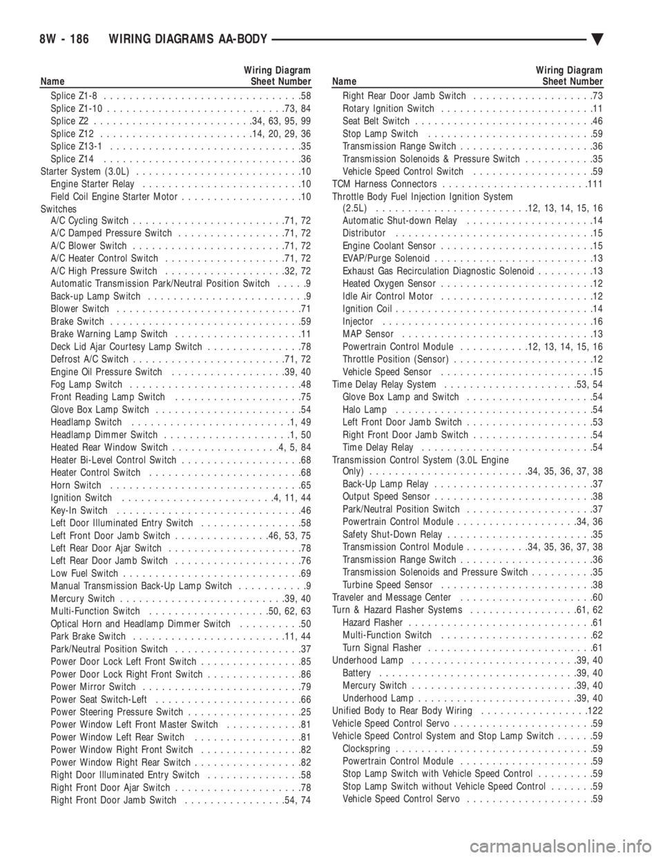
Wiring Diagram
Name Sheet Number
Splice Z1-8 ...............................58
Splice Z1-10 ........................... .73, 84
Splice Z2 ........................ .34, 63, 95, 99
Splice Z12 ....................... .14, 20, 29, 36
Splice Z13-1 ..............................35
Splice Z14 ...............................36
Starter System (3.0L) ..........................10
Engine Starter Relay .........................10
Field Coil Engine Starter Motor ...................10
Switches A/C Cycling Switch ....................... .71, 72
A/C Damped Pressure Switch .................71, 72
A/C Blower Switch ....................... .71, 72
A/C Heater Control Switch .................. .71, 72
A/C High Pressure Switch .................. .32, 72
Automatic Transmission Park/Neutral Position Switch .....9
Back-up Lamp Switch .........................9
Blower Switch .............................71
Brake Switch ..............................59
Brake Warning Lamp Switch ....................11
Deck Lid Ajar Courtesy Lamp Switch ...............78
Defrost A/C Switch ....................... .71, 72
Engine Oil Pressure Switch ..................39, 40
Fog Lamp Switch ...........................48
Front Reading Lamp Switch ....................75
Glove Box Lamp Switch .......................54
Headlamp Switch .........................1,49
Headlamp Dimmer Switch ....................1,50
Heated Rear Window Switch .................4,5,84
Heater Bi-Level Control Switch ...................68
Heater Control Switch ........................68
Horn Switch ..............................65
Ignition Switch ........................4,11,44
Key-In Switch .............................46
Left Door Illuminated Entry Switch ................58
Left Front Door Jamb Switch ...............46, 53, 75
Left Rear Door Ajar Switch .....................78
Left Rear Door Jamb Switch ....................76
Low Fuel Switch ............................69
Manual Transmission Back-Up Lamp Switch ...........9
Mercury Switch ......................... .39, 40
Multi-Function Switch .................. .50, 62, 63
Optical Horn and Headlamp Dimmer Switch ..........50
Park Brake Switch ....................... .11, 44
Park/Neutral Position Switch ....................37
Power Door Lock Left Front Switch ................85
Power Door Lock Right Front Switch ...............86
Power Mirror Switch .........................79
Power Seat Switch-Left .......................66
Power Steering Pressure Switch ..................25
Power Window Left Front Master Switch ............81
Power Window Left Rear Switch .................81
Power Window Right Front Switch ................82
Power Window Right Rear Switch .................82
Right Door Illuminated Entry Switch ...............58
Right Front Door Ajar Switch ....................78
Right Front Door Jamb Switch ................54, 74Wiring Diagram
Name Sheet Number
Right Rear Door Jamb Switch ...................73
Rotary Ignition Switch ........................11
Seat Belt Switch ............................46
Stop Lamp Switch ..........................59
Transmission Range Switch .....................36
Transmission Solenoids & Pressure Switch ...........35
Vehicle Speed Control Switch ...................59
TCM Harness Connectors ...................... .111
Throttle Body Fuel Injection Ignition System (2.5L) ....................... .12, 13, 14, 15, 16
Automatic Shut-down Relay ....................14
Distributor ...............................15
Engine Coolant Sensor ........................15
EVAP/Purge Solenoid .........................13
Exhaust Gas Recirculation Diagnostic Solenoid .........13
Heated Oxygen Sensor ........................12
Idle Air Control Motor ........................12
Ignition Coil ...............................14
Injector .................................16
MAP Sensor ..............................13
Powertrain Control Module ...........12, 13, 14, 15, 16
Throttle Position (Sensor) ......................12
Vehicle Speed Sensor ........................15
Time Delay Relay System .................... .53, 54
Glove Box Lamp and Switch ....................54
Halo Lamp ...............................54
Left Front Door Jamb Switch ....................53
Right Front Door Jamb Switch ...................54
Time Delay Relay ...........................54
Transmission Control System (3.0L Engine Only) ........................ .34, 35, 36, 37, 38
Back-Up Lamp Relay .........................37
Output Speed Sensor .........................38
Park/Neutral Position Switch ....................37
Powertrain Control Module .................. .34, 36
Safety Shut-Down Relay .......................35
Transmission Control Module ..........34, 35, 36, 37, 38
Transmission Range Switch .....................36
Transmission Solenoids and Pressure Switch ..........35
Turbine Speed Sensor ........................38
Traveler and Message Center .....................60
Turn & Hazard Flasher Systems .................61, 62
Hazard Flasher .............................61
Multi-Function Switch ........................62
Turn Signal Flasher ..........................61
Underhood Lamp ......................... .39, 40
Battery .............................. .39, 40
Mercury Switch ......................... .39, 40
Underhood Lamp ........................ .39, 40
Unified Body to Rear Body Wiring .................122
Vehicle Speed Control Servo ......................59
Vehicle Speed Control System and Stop Lamp Switch ......59
Clockspring ...............................59
Powertrain Control Module .....................59
Stop Lamp Switch with Vehicle Speed Control .........59
Stop Lamp Switch without Vehicle Speed Control .......59
Vehicle Speed Control Servo ....................59
8W - 186 WIRING DIAGRAMS AA-BODY Ä
Page 1065 of 2438
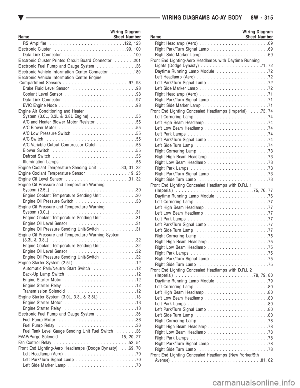
Wiring Diagram
Name Sheet Number
RS Amplifier ......................... .122, 123
Electronic Cluster ........................ .99, 100
Data Link Connector ....................... .100
Electronic Cluster Printed Circuit Board Connector .......201
Electronic Fuel Pump and Gauge System ..............36
Electronic Vehicle Information Center Connector ........189
Electronic Vehicle Information Center Engine Compartment Sensors ...................... .97, 98
Brake Fluid Level Sensor ......................98
Coolant Level Sensor .........................98
Data Link Connector .........................97
EVIC Engine Node ...........................98
Engine Air Conditioning and Heater System (3.0L, 3.3L & 3.8L Engine) ................55
A/C and Heater Blower Motor Resistor ..............55
A/C Blower Motor ...........................55
A/C Low Pressure Switch ......................55
A/C Switch ...............................55
A/C Variable Output Compressor Clutch .............55
Blower Switch .............................55
Defrost Switch .............................55
Illumination Lamps ..........................55
Engine Coolant Temperature Sending Unit ........30, 31, 32
Engine Coolant Temperature Sensor ..............19, 25
Engine Oil Level Sensor ..................... .31, 32
Engine Oil Pressure and Temperature Warning System (2.5L) .............................30
Engine Coolant Temperature Sending Unit ............30
Engine Oil Pressure Switch .....................30
Engine Oil Pressure and Temperature Warning System (3.0L) .............................31
Engine Coolant Temperature Sending Unit ............31
Engine Oil Level Sensor .......................31
Engine Oil Pressure Sending Unit/Switch ............31
Engine Oil Pressure and Temperature Warning System (3.3L & 3.8L) .............................32
Engine Coolant Temperature Sending Unit ............32
Engine Oil Level Sensor .......................32
Engine Oil Pressure Sending Unit/Switch ............32
Engine Starter System (2.5L) .....................12
Automatic Park/Neutral Start Switch ...............12
Back-Up Lamp Switch ........................12
Engine Starter Motor .........................12
Engine Starter Relay .........................12
Transmission Solenoid ........................12
Engine Starter System (3.0L, 3.3L & 3.8L) .............13
Engine Starter Motor .........................13
Engine Starter Relay .........................13
Electronic Fuel Pump and Gauge System ..............36
Fuel Pump Motor ...........................36
Fuel Pump Relay ...........................36
Fuel Tank Level Gauge Sending Unit Fuel Switch .......36
EVAP/Purge Solenoid .................... .15, 20, 27
Fan Control Relay ......................... .52, 54
Front End Lighting-Aero Headlamps (Dodge Dynasty) . . .69, 70 Left Headlamp (Aero) .........................70
Left Park/Turn Signal Lamp .....................70
Left Side Marker Lamp ........................70Wiring Diagram
Name Sheet Number
Right Headlamp (Aero) ........................69
Right Park/Turn Signal Lamp ....................69
Right Side Marker Lamp .......................69
Front End Lighting-Aero Headlamps with Daytime Running Lights (Dodge Dynasty) .................... .71, 72
Daytime Running Lamp Module ..................72
Left Headlamp (Aero) .........................72
Left Park/Turn Signal Lamp .....................72
Left Side Marker Lamp ........................72
Right Headlamp (Aero) ........................71
Right Park/Turn Signal Lamp ....................71
Right Side Marker Lamp .......................71
Front End Lighting Concealed Headlamps (Imperial) . . . .73, 74
Left Cornering Lamp .........................74
Left High Beam Headlamp ......................74
Left Low Beam Headlamp ......................74
Left Park Lamps ............................74
Left Park/Turn Signal Lamp .....................74
Left Side Turn Lamp .........................74
Right Cornering Lamp ........................73
Right High Beam Headlamp .....................73
Right Low Beam Headlamp .....................73
Right Park Lamps ...........................73
Right Park/Turn Signal Lamp ....................73
Right Side Turn Lamp ........................73
Front End Lighting Concealed Headlamps with D.R.L.1 (Imperial) .......................... .75, 76, 77
Daytime Running Lamp Module ..................76
Left Cornering Lamp .........................77
Left High Beam Headlamp ......................77
Left Low Beam Headlamp ......................77
Left Park Lamps ............................77
Left Park/Turn Signal Lamp .....................77
Left Side Turn Lamp .........................77
Right Cornering Lamp ........................75
Right High Beam Headlamp .....................75
Right Low Beam Headlamp .....................75
Right Park Lamps ...........................75
Right Park/Turn Signal Lamp ....................75
Right Side Turn Lamp ........................75
Front End Lighting Concealed Headlamps with D.R.L.2 (Imperial) .......................... .78, 79, 80
Daytime Running Lamp Module ..................79
Left Cornering Lamp .........................80
Left High Beam Headlamp ......................80
Left Low Beam Headlamp ......................80
Left Park Lamps ............................80
Left Park/Turn Signal Lamp .....................80
Left Side Turn Lamp .........................80
Right Cornering Lamp ........................78
Right High Beam Headlamp .....................78
Right Low Beam Headlamp .....................78
Right Park Lamps ...........................78
Right Park/Turn Signal Lamp ....................78
Right Side Turn Lamp ........................78
Front End Lighting Concealed Headlamps (New Yorker/5th Avenue) .............................. .81, 82
Ä WIRING DIAGRAMS AC-AY BODY 8W - 315
Page 1066 of 2438
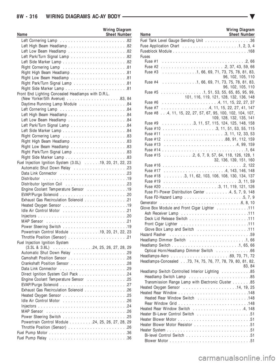
Wiring Diagram
Name Sheet Number
Left Cornering Lamp .........................82
Left High Beam Headlamp ......................82
Left Low Beam Headlamp ......................82
Left Park/Turn Signal Lamp .....................82
Left Side Marker Lamp ........................82
Right Cornering Lamp ........................81
Right High Beam Headlamp .....................81
Right Low Beam Headlamp .....................81
Right Park/Turn Signal Lamp ....................81
Right Side Marker Lamp .......................81
Front End Lighting Concealed Headlamps with D.R.L. (New Yorker/5th Avenue) ................... .83, 84
Daytime Running Lamp Module ..................84
Left Cornering Lamp .........................84
Left High Beam Headlamp ......................84
Left Low Beam Headlamp ......................84
Left Park/Turn Signal Lamp .....................84
Left Side Marker Lamp ........................84
Right Cornering Lamp ........................83
Right High Beam Headlamp .....................83
Right Low Beam Headlamp .....................83
Right Park/Turn Signal Lamp ....................83
Right Side Marker Lamp .......................83
Fuel Injection Ignition System (3.0L) ......19, 20, 21, 22, 23
Automatic Shut Down Relay ....................23
Data Link Connector .........................23
Distributor ...............................19
Distributor Ignition Coil .......................23
Engine Coolant Temperature Sensor ...............19
EVAP/Purge Solenoid .........................20
Exhaust Gas Recirculation Solenoid ................21
Heated Oxygen Sensor ........................19
Idle Air Control Motor ........................21
Injectors .................................20
MAP Sensor ..............................21
Power Steering Switch ........................19
Powertrain Control Module ...........19, 20, 21, 22, 23
Throttle Position (Sensor) ......................21
Fuel Injection Ignition System (3.3L & 3.8L) .............. .24, 25, 26, 27, 28, 29
Automatic Shut Down Relay ....................29
Camshaft Position Sensor ......................28
Crankshaft Position Sensor .....................28
Data Link Connector .........................29
Direct Ignition System Coil Pack ..................24
Engine Coolant Temperature Sensor ...............25
EVAP/Purge Solenoid .........................27
Exhaust Gas Recirculation Solenoid ................26
Heated Oxygen Sensor ........................25
Idle Air Control Motor ........................26
Injectors .................................24
MAP Sensor ..............................26
Power Steering Switch ........................25
Powertrain Control Module .........24, 25, 26, 27, 28, 29
Throttle Position (Sensor) ......................26
Fuel Pump Motor .............................36
Fuel Pump Relay .............................36Wiring Diagram
Name Sheet Number
Fuel Tank Level Gauge Sending Unit .................36
Fuse Application Chart .....................1,2,3,4
Fuseblock Module ........................... .168
Fuses Fuse #1 ...............................2,66
Fuse #2 ........................2,37,43,59,66
Fuse #3 .............1,66,69,71,73,75,78,81,83,
96, 102, 105, 110
Fuse #4 .............1,66,69,71,73,75,78,81,83,
96, 102, 105, 110
Fuse #5 ................1,51,53,55,65,85,95,99,
101, 116, 119, 121, 128, 132, 136, 148
Fuse #6 .....................4,11,15,22,27,37
Fuse #7 ..................4,11,15,22,27,41,147
Fuse #8 . . .4, 11, 15, 22, 27, 57, 67, 95, 100, 102, 104, 107, 109, 128, 132, 135, 141
Fuse #9 ............3,11,57, 115, 124, 125, 148, 158
Fuse #10 ....................3,11,51,53,55,115
Fuse #11 .......................3,11,12,33,53
Fuse #12 ...................... .88, 91, 112, 159
Fuse #13 ...........................4,99,159
Fuse #14 ...............................1,64
Fuse #15 ...........2,6,7,9,57,64, 118, 126, 128, 1
32, 136, 139, 151, 160
Fuse #16 ..............................2,122
Fuse #17 .......................4, 143, 146, 148
Fuse #18 ........3,11,62, 103, 106, 108, 130, 134, 137
Fuse #19 ............................3,11,59
Fuse #20 .....................3,11, 119, 121, 126
Fuse F1-Power Distribution Center .........4,5,7,9,148
Fuse F2-Hazard Lamp ......................5,7,9
Generator ..............................6,8,10
Glove Box Module and Front Cigar Lighter ............111
Ash Receiver Lamp ........................ .111
Deck Lid Release Switch ..................... .111
Front Cigar Lighter ........................ .111
Glove Box Lamp and Switch ...................111
Hazard Flasher ..............................59
Headlamp Dimmer Switch .....................1,66
Headlamp Switch .........................1,65,66
Optical Horn/Headlamp Dimmer Switch .............66
Headlamps-Aero ..................... .69, 70, 71, 72
Headlamps-Concealed . . .73, 74, 75, 76, 77, 78, 79, 80, 81, 82, 83, 84
Headlamp Switch Controlled Interior Lighting ...........85
Headlamp Switch Lamp .......................85
Transmission Range Lamp with Electronic Cluster .......85
Heated Oxygen Sensor ................... .14, 19, 25
Heated Rear Window ......................... .148
Heated Rear Window Switch ...................148
Rear Window Grid ......................... .148
Heated Rear Window Switch ...................4,148
Heater Bi-Lever Control Switch ....................51
Heater Blower Motor ...........................51
Heater Blower Motor Resistor .....................51
Heater System ...............................51
Bi-level Control Switch ........................51
Blower Motor ..............................51
8W - 316 WIRING DIAGRAMS AC-AY BODY Ä
Page 1069 of 2438
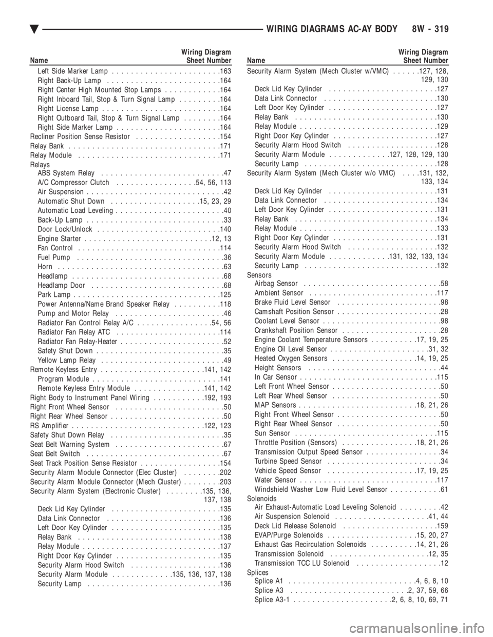
Wiring Diagram
Name Sheet Number
Left Side Marker Lamp ...................... .163
Right Back-Up Lamp ....................... .164
Right Center High Mounted Stop Lamps ............164
Right Inboard Tail, Stop & Turn Signal Lamp .........164
Right License Lamp ........................ .164
Right Outboard Tail, Stop & Turn Signal Lamp ........164
Right Side Marker Lamp ..................... .164
Recliner Position Sense Resistor ..................154
Relay Bank ............................... .171
Relay Module ............................. .171
Relays ABS System Relay ..........................47
A/C Compressor Clutch .................54, 56, 113
Air Suspension .............................42
Automatic Shut Down .................. .15, 23, 29
Automatic Load Leveling .......................40
Back-Up Lamp .............................33
Door Lock/Unlock ......................... .140
Engine Starter .......................... .12, 13
Fan Control ............................. .114
Fuel Pump ...............................36
Horn ...................................63
Headlamp ................................68
Headlamp Door ............................68
Park Lamp .............................. .125
Power Antenna/Name Brand Speaker Relay ..........118
Pump and Motor Relay .......................46
Radiator Fan Control Relay A/C ................54, 56
Radiator Fan Relay ATC ..................... .114
Radiator Fan Relay-Heater ......................52
Safety Shut Down ...........................35
Yellow Lamp Relay ..........................49
Remote Keyless Entry ..................... .141, 142
Program Module .......................... .141
Remote Keyless Entry Module ...............141, 142
Right Body to Instrument Panel Wiring ...........192, 193
Right Front Wheel Sensor .......................50
Right Rear Wheel Sensor ........................50
RS Amplifier ........................... .122, 123
Safety Shut Down Relay ........................35
Seat Belt Warning System .......................67
Seat Belt Switch .............................67
Seat Track Position Sense Resistor .................154
Security Alarm Module Connector (Elec Cluster) ........202
Security Alarm Module Connector (Mech Cluster) ........203
Security Alarm System (Electronic Cluster) ........135, 136,
137, 138
Deck Lid Key Cylinder ...................... .135
Data Link Connector ....................... .136
Left Door Key Cylinder ...................... .135
Relay Bank ............................. .138
Relay Module ............................ .137
Right Door Key Cylinder ..................... .135
Security Alarm Hood Switch ...................136
Security Alarm Module .............135, 136, 137, 138
Security Lamp ........................... .136Wiring Diagram
Name Sheet Number
Security Alarm System (Mech Cluster w/VMC) ......127, 128,
129, 130
Deck Lid Key Cylinder ...................... .127
Data Link Connector ....................... .130
Left Door Key Cylinder ...................... .127
Relay Bank ............................. .130
Relay Module ............................ .129
Right Door Key Cylinder ..................... .127
Security Alarm Hood Switch ...................128
Security Alarm Module .............127, 128, 129, 130
Security Lamp ........................... .128
Security Alarm System (Mech Cluster w/o VMC) . . . .131, 132,
133, 134
Deck Lid Key Cylinder ...................... .131
Data Link Connector ....................... .134
Left Door Key Cylinder ...................... .131
Relay Bank ............................. .134
Relay Module ............................ .133
Right Door Key Cylinder ..................... .131
Security Alarm Hood Switch ...................132
Security Alarm Module .............131, 132, 133, 134
Security Lamp ........................... .132
Sensors Airbag Sensor .............................58
Ambient Sensor .......................... .117
Brake Fluid Level Sensor ......................98
Camshaft Position Sensor ......................28
Coolant Level Sensor .........................98
Crankshaft Position Sensor .....................28
Engine Coolant Temperature Sensors ..........17, 19, 25
Engine Oil Level Sensor .................... .31, 32
Heated Oxygen Sensors ................. .14, 19, 25
Height Sensors ............................44
In Car Senso r............................ .115
Left Front Wheel Sensor .......................50
Left Rear Wheel Sensor .......................50
MAP Sensors ........................ .18, 21, 26
Right Front Wheel Sensor ......................50
Right Rear Wheel Sensor ......................50
Sun Sensor ............................. .115
Throttle Position (Sensors) ................18, 21, 26
Transmission Output Speed Sensor ................34
Turbine Speed Sensor ........................34
Vehicle Speed Sensor .................. .17, 19, 25
Water Sensor ............................ .117
Windshield Washer Low Fluid Level Sensor ...........61
Solenoids Air Exhaust-Automatic Load Leveling Solenoid .........42
Air Suspension Solenoid ................... .41, 44
Deck Lid Release Solenoid ................... .159
EVAP/Purge Solenoids .................. .15, 20, 27
Exhaust Gas Recirculation Solenoids ..........14, 21, 26
Transmission Solenoid .................... .12, 35
Transmission TCC LU Solenoid ..................12
Splices Splice A1 ...........................4,6,8,10
Splice A3 .........................2,37,59,66
Splice A3-1 .....................2,6,8,10,69,71
Ä WIRING DIAGRAMS AC-AY BODY 8W - 319
Page 1071 of 2438
Wiring Diagram
Name Sheet Number
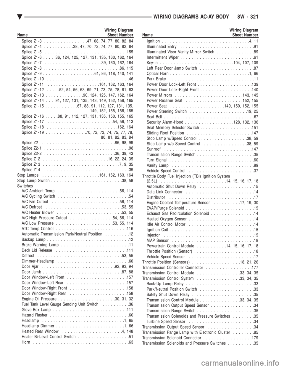
Splice Z1-3 ............... .47, 68, 74, 77, 80, 82, 84
Splice Z1-4 .......... .38, 47, 70, 72, 74, 77, 80, 82, 84
Splice Z1-5 ............................. .155
Splice Z1-6 .....36, 124, 125, 127, 131, 135, 160, 162, 164
Splice Z1-7 .................... .39, 160, 162, 164
Splice Z1-8 ........................... .86, 115
Splice Z1-9 .................. .61, 86, 118, 140, 141
Splice Z1-10 ..............................46
Splice Z1-11 .................. .161, 162, 163, 164
Splice Z1-12 .....52, 54, 56, 63, 69, 71, 73, 75, 78, 81, 83
Splice Z1-13 ............. .90, 124, 125, 147, 162, 164
Splice Z1-14 . . . .91, 127, 131, 135, 143, 149, 152, 158, 165
Splice Z1-15 ........... .67, 88, 91, 112, 127, 131, 135,
149, 152, 155, 158, 165
Splice Z1-16 .....88, 91, 112, 127, 131, 135, 150, 155, 165
Splice Z1-17 ....................... .54, 56, 113
Splice Z1-18 ......................... .162, 164
Splice Z1-19 .............. .70, 72, 73, 74, 75, 77, 78,
80, 81, 82, 83, 84
Splice Z2 .......................... .86, 98, 99
Splice Z2-1 ...............................98
Splice Z2-2 ......................... .36, 39, 43
Splice Z12 ....................... .16, 22, 24, 35
Splice Z13 ............................7,9,35
Splice Z14 ...............................35
Stop Lamps .................... .161, 162, 163, 164
Stop Lamp Switch ......................... .38, 59
Switches A/C Ambient Temp ...................... .56, 114
A/C Cycling Switch ..........................54
A/C Fan Cutout ........................ .56, 114
A/C Defrost ........................... .53, 55
A/C Heater Blower ....................... .53, 55
A/C High Pressure Cutout ................54, 56, 114
A/C Low Pressure .................... .53, 55, 114
ATC Temp Control ......................... .116
Automatic Transmission Park/Neutral Position .........12
Backup Lamp ..............................12
Brake Warning Lamp .........................11
Deck Lid Release ......................... .111
Defrost .............................. .53, 55
Dimmer-Headlamp ..........................66
Door Ajar .......................... .92, 93, 94
Door Jamb ............................ .87, 88
Door Window-Left Front ..................... .157
Door Window-Left Rear ..................... .157
Door Window-Right Front .................... .158
Door Window-Right Rear .................... .158
Engine Oil Pressure .................... .30, 31, 32
Fuel Tank Level Gauge Sending Unit Switch ..........36
Glove Box Lamp .......................... .111
Hazard Flasher .............................60
Headlamp ..............................1,65
Headlamp Dimmer .........................1,66
Heated Rear Window ......................4,148
Heater Bi-Level Control Switch ...................51
Horn ...................................63Wiring Diagram
Name Sheet Number
Ignition ................................4,11
Illuminated Entry ...........................91
Illuminated Visor Vanity Mirror Switch ..............89
Intermittent Wiper ...........................61
Key-in .......................... .104, 107, 109
Left Rear Door Jamb Switch ....................87
Optical Horn .............................1,66
Park Brake ...............................11
Power Door Lock-Left Front ................... .139
Power Door Lock-Right Front ...................140
Power Mirrors ........................ .143, 145
Power Recliner Seat .................... .152, 155
Power Seat ................... .149, 150, 152, 155
Power Steering Switch .................... .19, 25
Seat Belt .................................67
Security Alarm-Hood ................. .128, 132, 136
Seat Memory Selector Switch ...................151
Sliding Roof Position ....................... .147
Stop Lamp w/Speed Control ..................38, 59
Stop Lamp w/o Speed Control ................38, 59
Sunroof ............................... .147
Transmission Range Switch .....................35
Turn Signal ...............................60
Vanity Lamp ..............................89
Vehicle Speed Control ........................37
Throttle Body Fuel Injection (TBI) Ignition System (2.5L) ....................... .14, 15, 16, 17, 18
Automatic Shut Down Relay ....................15
Data Link Connector .........................14
Distributor ...............................17
Engine Coolant Temperature Sensor ..........17, 19, 30
EVAP/Purge Solenoid .........................15
Exhaust Gas Recirculation Solenoid ................14
Heated Oxygen Sensor ........................14
Idle Air Control Motor ........................14
Ignition Coil ...............................15
Injector .................................15
MAP Sensor ..............................18
Powertrain Control Module ...........14, 15, 16, 17, 18
Throttle Position (Sensor) ......................18
Vehicle Speed Sensor ........................17
Throttle Position (Sensors) ..................18, 21, 26
Transmission Controller Connector .................177
Transmission Control Module ................33, 34, 35
Transmission Control System ................33, 34, 35
Back-Up Lamp Relay .........................33
Park/Neutral Position Switch ....................33
Safety Shut Down Relay .......................35
Transmission Control Module ...............33, 34, 35
Transmission Output Speed Sensor ................34
Transmission Range Switch .....................35
Transmission Solenoids and Pressure Switches ........35
Turbine Speed Sensor ........................34
Transmission Output Speed Sensor .................34
Transmission Range Lamp with Electronic Cluster ........85
Transmission Solenoid Connector ..................179
Transmission Solenoids and Pressure Switches ..........35
Ä WIRING DIAGRAMS AC-AY BODY 8W - 321
Page 1284 of 2438
Wiring Diagram
Name Sheet Number
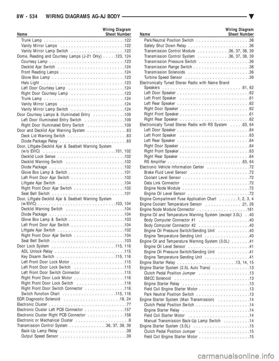
Trunk Lamp ............................. .122
Vanity Mirror Lamps ....................... .122
Vanity Mirror Lamp Switch ................... .122
Dome, Reading and Courtesy Lamps (J-21 Only) .....123, 124
Courtesy Lamp ........................... .123
Decklid Ajar Switch ........................ .124
Front Reading Lamps ....................... .124
Glove Box Lamp .......................... .123
Halo Light .............................. .123
Left Door Courtesy Lamp .................... .124
Right Door Courtesy Lamp ................... .123
Trunk Lamp ............................. .124
Vanity Mirror Lamps ....................... .124
Vanity Mirror Lamp Switch ................... .124
Door Courtesy Lamps & Illuminated Entry ............109
Left Door Illuminated Entry Switch ...............109
Right Door Illuminated Entry Switch ..............109
Door and Decklid Ajar Warning System ...............83
Deck Lid Warning Switch ......................83
Diode Package Relay .........................83
Door, Liftgate-Decklid Ajar & Seatbelt Warning System (w/o EVIC) .......................... .101, 102
Decklid Lock Sense ........................ .102
Decklid Warning Switch ..................... .102
Diode Package ........................... .102
Glove Box Lamp & Switch .................... .101
Left Front Door Ajar Switch ................... .102
Liftgate Ajar Switch ........................ .104
Right Front Door Ajar Switch ...................102
Seat Belt Switch .......................... .101
Door, Liftgate Decklid Ajar & Seatbelt Warning System (w/EVIC) ............................ .103, 104
Decklid Warning Switch ..................... .104
Diode Package ........................... .104
Glove Box Lamp & Switch .................... .103
Left Front Door Ajar Switch ................... .104
Liftgate Ajar Switch ........................ .102
Right Front Door Ajar Switch ...................104
Seat Belt Switch .......................... .103
Door Lock System ....................... .115, 116
ADL Unlock Relay ......................... .115
Key Disarm Switch ..................... .115, 116
Left Front Door Lock Motor ................... .115
Left Front Door Lock Switch ...................115
Left Front Door Switch Connector ................115
Right Front Door Lock Motor ...................116
Right Front Door Lock Switch ..................116
Right Front Door Switch Connector ...............116
Switch Function Chart ................... .115, 116
EGR Diagnostic Solenoid .................... .18, 24
Electronic Cluster .............................77
Electronic Cluster Left PCB Connector ...............157
Electronic Cluster Right PCB Connector ..............158
Electronic or Mechanical Cluster ....................6
Transmission Control System ..............36, 37, 38, 39
Back-Up Lamp Relay .........................38
Output Speed Sensor .........................39Wiring Diagram
Name Sheet Number
Park/Neutral Position Switch ....................38
Safety Shut Down Relay .......................36
Transmission Control Module ............36, 37, 38, 39
Transmission Control System ............36, 37, 38, 39
Transmission Pressure Switch ...................36
Transmission Range Switch .....................38
Transmission Solenoids .......................36
Turbine Speed Sensor ........................39
Electronically Tuned Stereo Radio with Name Brand Speakers ............................. .61, 62
Left Door Speaker ...........................62
Left Front Speaker ..........................61
Left Rear Speaker ...........................62
Right Door Speaker ..........................62
Right Front Speaker ..........................61
Right Rear Speaker ..........................62
Electronically Tuned Stereo Radio with RS System .....63, 64
Left Door Speaker ...........................64
Left Front Speaker ..........................63
Left Rear Speaker ...........................64
Right Door Speaker ..........................64
Right Front Speaker ..........................63
Right Rear Speaker ..........................64
RS Amplifier ........................... .63, 64
Electronic Vehicle Information Center ................72
Brake Fluid Level Sensor ......................72
Coolant Level Sensor .........................72
Data Link Connector .........................72
Engine Node Module .........................72
Engine Oil Level Sensor .......................72
Engine Compartment Fuse Application Chart .......1,2,3,4
Engine Coolant Temperature Sensor ..............21, 26
Engine Node Module Connector ...................161
Engine Oil and Temperature Warning System (except 3.0L) . .40 Body Computer Connector #1 ...................40
Body Computer Connector #2 ...................40
Engine Oil Pressure Switch/Sending Unit ............40
Engine Temperature Sending Unit .................40
Engine Oil and Temperature Warning System (3.0L) .......41
Engine Oil Level Sensor .......................41
Engine Oil Pressure Switch/Sending Unit ............41
Engine Temperature Sending Unit .................41
Engine Starter Relay ..................... .13, 14, 15
Engine Starter System (2.5L Auto Trans) ..............13
Clutch Pedal Position Jumper ...................13
EMCC Solenoid ............................13
Engine Starter Relay .........................13
Field Coil Engine Starter Motor ...................13
Park Neutral Position Switch ....................13
Engine Starter System (Man Transmission) ............14
Clutch Pedal Position Switch ....................14
Engine Starter Relay .........................14
Field Coil Starter Motor .......................14
Manual Transmission Back-Up Lamp Switch ..........14
Engine Starter System (3.0L) .....................15
Clutch Pedal Position Jumper ...................15
Field Coil Engine Starter Motor ...................15
8W - 534 WIRING DIAGRAMS AG-AJ BODY Ä
Page 1285 of 2438
Wiring Diagram
Name Sheet Number
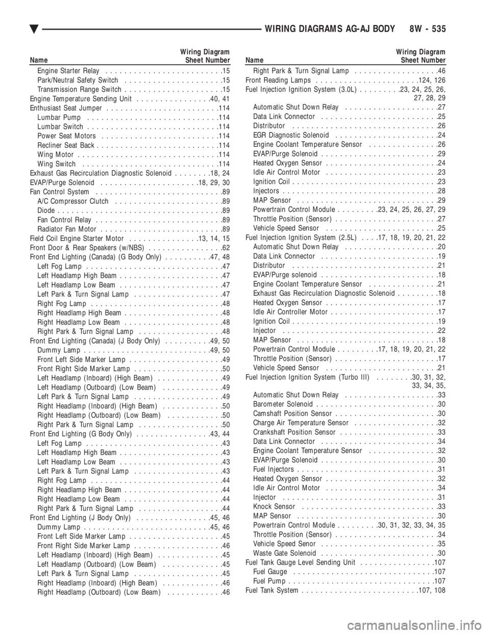
Engine Starter Relay .........................15
Park/Neutral Safety Switch .....................15
Transmission Range Switch .....................15
Engine Temperature Sending Unit ................40, 41
Enthusiast Seat Jumper ....................... .114
Lumbar Pump ........................... .114
Lumbar Switch ........................... .114
Power Seat Motors ........................ .114
Recliner Seat Back ......................... .114
Wing Motor ............................. .114
Wing Switch ............................ .114
Exhaust Gas Recirculation Diagnostic Solenoid ........18, 24
EVAP/Purge Solenoid .................... .18, 29, 30
Fan Control System ...........................89
A/C Compressor Clutch .......................89
Diode ...................................89
Fan Control Relay ...........................89
Radiator Fan Motor ..........................89
Field Coil Engine Starter Motor ...............13, 14, 15
Front Door & Rear Speakers (w/NBS) ................62
Front End Lighting (Canada) (G Body Only) ..........47, 48
Left Fog Lamp .............................47
Left Headlamp High Beam ......................47
Left Headlamp Low Beam ......................47
Left Park & Turn Signal Lamp ...................47
Right Fog Lamp ............................48
Right Headlamp High Beam .....................48
Right Headlamp Low Beam .....................48
Right Park & Turn Signal Lamp ..................48
Front End Lighting (Canada) (J Body Only) ..........49, 50
Dummy Lamp .......................... .49, 50
Front Left Side Marker Lamp ....................49
Front Right Side Marker Lamp ...................50
Left Headlamp (Inboard) (High Beam) ..............49
Left Headlamp (Outboard) (Low Beam) .............49
Left Park & Turn Signal Lamp ...................49
Right Headlamp (Inboard) (High Beam) .............50
Right Headlamp (Outboard) (Low Beam) ............50
Right Park & Turn Signal Lamp ..................50
Front End Lighting (G Body Only) ................43, 44
Left Fog Lamp .............................43
Left Headlamp High Beam ......................43
Left Headlamp Low Beam ......................43
Left Park & Turn Signal Lamp ...................43
Right Fog Lamp ............................44
Right Headlamp High Beam .....................44
Right Headlamp Low Beam .....................44
Right Park & Turn Signal Lamp ..................44
Front End Lighting (J Body Only) ................45, 46
Dummy Lamp .......................... .45, 46
Front Left Side Marker Lamp ....................45
Front Right Side Marker Lamp ...................46
Left Headlamp (Inboard) (High Beam) ..............45
Left Headlamp (Outboard) (Low Beam) .............45
Left Park & Turn Signal Lamp ...................45
Right Headlamp (Inboard) (High Beam) .............46
Right Headlamp (Outboard) (Low Beam) ............46Wiring Diagram
Name Sheet Number
Right Park & Turn Signal Lamp ..................46
Front Reading Lamps ..................... .124, 126
Fuel Injection Ignition System (3.0L) .........23, 24, 25, 26,
27, 28, 29
Automatic Shut Down Relay ....................27
Data Link Connector .........................25
Distributor ...............................26
EGR Diagnostic Solenoid ......................24
Engine Coolant Temperature Sensor ...............26
EVAP/Purge Solenoid .........................29
Heated Oxygen Sensor ........................24
Idle Air Control Motor ........................23
Ignition Coil ...............................23
Injectors .................................28
MAP Sensor ..............................29
Powertrain Control Module .........23, 24, 25, 26, 27, 29
Throttle Position (Sensor) ......................27
Vehicle Speed Sensor ........................25
Fuel Injection Ignition System (2.5L) . . . .17, 18, 19, 20, 21, 22
Automatic Shut Down Relay ....................20
Data Link Connector .........................19
Distributor ...............................21
EVAP/Purge solenoid .........................18
Engine Coolant Temperature Sensor ...............21
Exhaust Gas Recirculation Diagnostic Solenoid .........18
Heated Oxygen Sensor ........................17
Idle Air Controller Motor .......................17
Ignition Coil ...............................19
Injector .................................22
MAP Sensor ..............................18
Powertrain Control Module .........17, 18, 19, 20, 21, 22
Throttle Position (Sensor) ......................17
Vehicle Speed Sensor ........................21
Fuel Injection Ignition System (Turbo III) ........30, 31, 32,
33, 34, 35,
Automatic Shut Down Relay ....................33
Barometer Solenoid ..........................30
Camshaft Position Sensor ......................30
Charge Air Temperature Sensor ..................32
Crankshaft Position Sensor .....................33
Data Link Connector .........................34
Engine Coolant Temperature Sensor ...............32
EVAP/Purge Solenoid .........................30
Fuel Injectors ..............................31
Heated Oxygen Sensor ........................32
Idle Air Control Motor ........................34
Injector .................................31
Knock Sensor .............................33
MAP Sensor ..............................30
Powertrain Control Module .........30, 31, 32, 33, 34, 35
Throttle Position (Sensor) ......................34
Vehicle Speed Senor .........................35
Waste Gate Solenoid .........................30
Fuel Tank Gauge Level Sending Unit ................107
Fuel Gauge ............................. .107
Fuel Pump .............................. .107
Fuel Tank System ........................ .107, 108
Ä WIRING DIAGRAMS AG-AJ BODY 8W - 535
Page 1288 of 2438
Wiring Diagram
Name Sheet Number
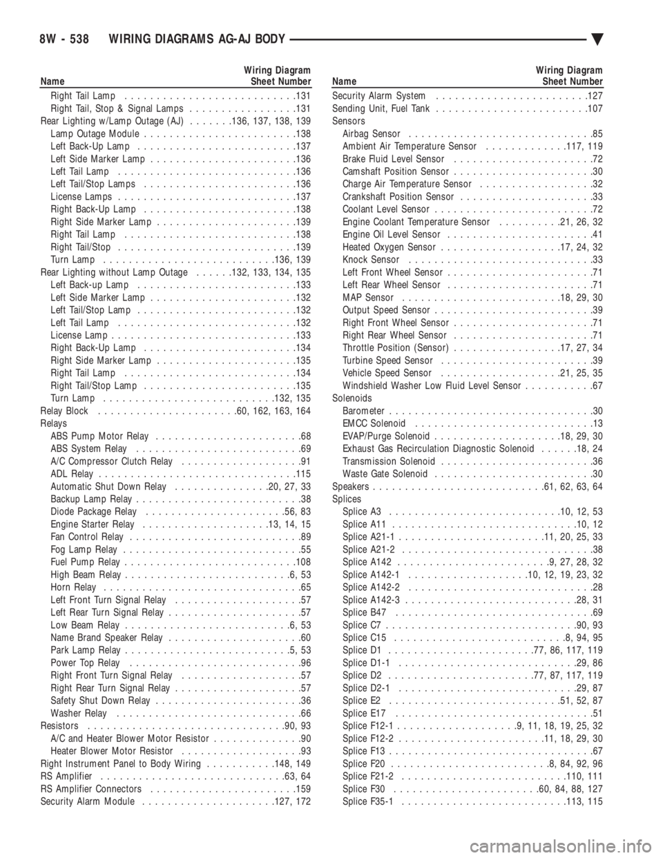
Right Tail Lamp .......................... .131
Right Tail, Stop & Signal Lamps .................131
Rear Lighting w/Lamp Outage (AJ) .......136, 137, 138, 139
Lamp Outage Module ....................... .138
Left Back-Up Lamp ........................ .137
Left Side Marker Lamp ...................... .136
Left Tail Lamp ........................... .136
Left Tail/Stop Lamps ....................... .136
License Lamps ........................... .137
Right Back-Up Lamp ....................... .138
Right Side Marker Lamp ..................... .139
Right Tail Lamp .......................... .138
Right Tail/Stop ........................... .139
Turn Lamp .......................... .136, 139
Rear Lighting without Lamp Outage ......132, 133, 134, 135
Left Back-up Lamp ........................ .133
Left Side Marker Lamp ...................... .132
Left Tail/Stop Lamp ........................ .132
Left Tail Lamp ........................... .132
License Lamp ............................ .133
Right Back-Up Lamp ....................... .134
Right Side Marker Lamp ..................... .135
Right Tail Lamp .......................... .134
Right Tail/Stop Lamp ....................... .135
Turn Lamp .......................... .132, 135
Relay Block ..................... .60, 162, 163, 164
Relays ABS Pump Motor Relay .......................68
ABS System Relay ..........................69
A/C Compressor Clutch Relay ...................91
ADL Relay .............................. .115
Automatic Shut Down Relay ...............20, 27, 33
Backup Lamp Relay ..........................38
Diode Package Relay ..................... .56, 83
Engine Starter Relay ................... .13, 14, 15
Fan Control Relay ...........................89
Fog Lamp Relay ............................55
Fuel Pump Relay .......................... .108
High Beam Relay ..........................6,53
Horn Relay ...............................65
Left Front Turn Signal Relay ....................57
Left Rear Turn Signal Relay .....................57
Low Beam Relay ..........................6,53
Name Brand Speaker Relay .....................60
Park Lamp Relay ..........................5,53
Power Top Relay ...........................96
Right Front Turn Signal Relay ...................57
Right Rear Turn Signal Relay ....................57
Safety Shut Down Relay .......................36
Washer Relay .............................66
Resistors .............................. .90, 93
A/C and Heater Blower Motor Resistor ..............90
Heater Blower Motor Resistor ...................93
Right Instrument Panel to Body Wiring ...........148, 149
RS Amplifier ............................ .63, 64
RS Amplifier Connectors ...................... .159
Security Alarm Module .................... .127, 172Wiring Diagram
Name Sheet Number
Security Alarm System ....................... .127
Sending Unit, Fuel Tank ....................... .107
Sensors Airbag Sensor .............................85
Ambient Air Temperature Sensor .............117, 119
Brake Fluid Level Sensor ......................72
Camshaft Position Sensor ......................30
Charge Air Temperature Sensor ..................32
Crankshaft Position Sensor .....................33
Coolant Level Sensor .........................72
Engine Coolant Temperature Sensor ..........21, 26, 32
Engine Oil Level Sensor .......................41
Heated Oxygen Sensor .................. .17, 24, 32
Knock Sensor .............................33
Left Front Wheel Sensor .......................71
Left Rear Wheel Sensor .......................71
MAP Sensor ........................ .18, 29, 30
Output Speed Sensor .........................39
Right Front Wheel Sensor ......................71
Right Rear Wheel Sensor ......................71
Throttle Position (Sensor) .................17, 27, 34
Turbine Speed Sensor ........................39
Vehicle Speed Sensor .................. .21, 25, 35
Windshield Washer Low Fluid Level Sensor ...........67
Solenoids Barometer ................................30
EMCC Solenoid ............................13
EVAP/Purge Solenoid ................... .18, 29, 30
Exhaust Gas Recirculation Diagnostic Solenoid ......18, 24
Transmission Solenoid ........................36
Waste Gate Solenoid .........................30
Speakers .......................... .61, 62, 63, 64
Splices Splice A3 .......................... .10, 12, 53
Splice A11 ............................ .10, 12
Splice A21-1 ...................... .11, 20, 25, 33
Splice A21-2 ..............................38
Splice A142 ........................9,27,28,32
Splice A142-1 .................. .10, 12, 19, 23, 32
Splice A142-2 .............................28
Splice A142-3 .......................... .28, 31
Splice B47 ...............................69
Splice C7 ............................. .90, 93
Splice C15 ...........................8,94,95
Splice D1 ...................... .77, 86, 117, 119
Splice D1-1 ........................... .29, 86
Splice D2 ...................... .77, 87, 117, 119
Splice D2-1 ........................... .29, 87
Splice E2 .......................... .51, 52, 87
Splice E17 ...............................51
Splice F12-1 ...................9,11,18,19,25,32
Splice F12-2 ...................... .11, 18, 29, 30
Splice F13 ................................67
Splice F20 .........................8,84,92,96
Splice F21-2 ......................... .110, 111
Splice F30 ...................... .60, 84, 88, 127
Splice F35-1 ......................... .113, 115
8W - 538 WIRING DIAGRAMS AG-AJ BODY Ä
Page 1468 of 2438
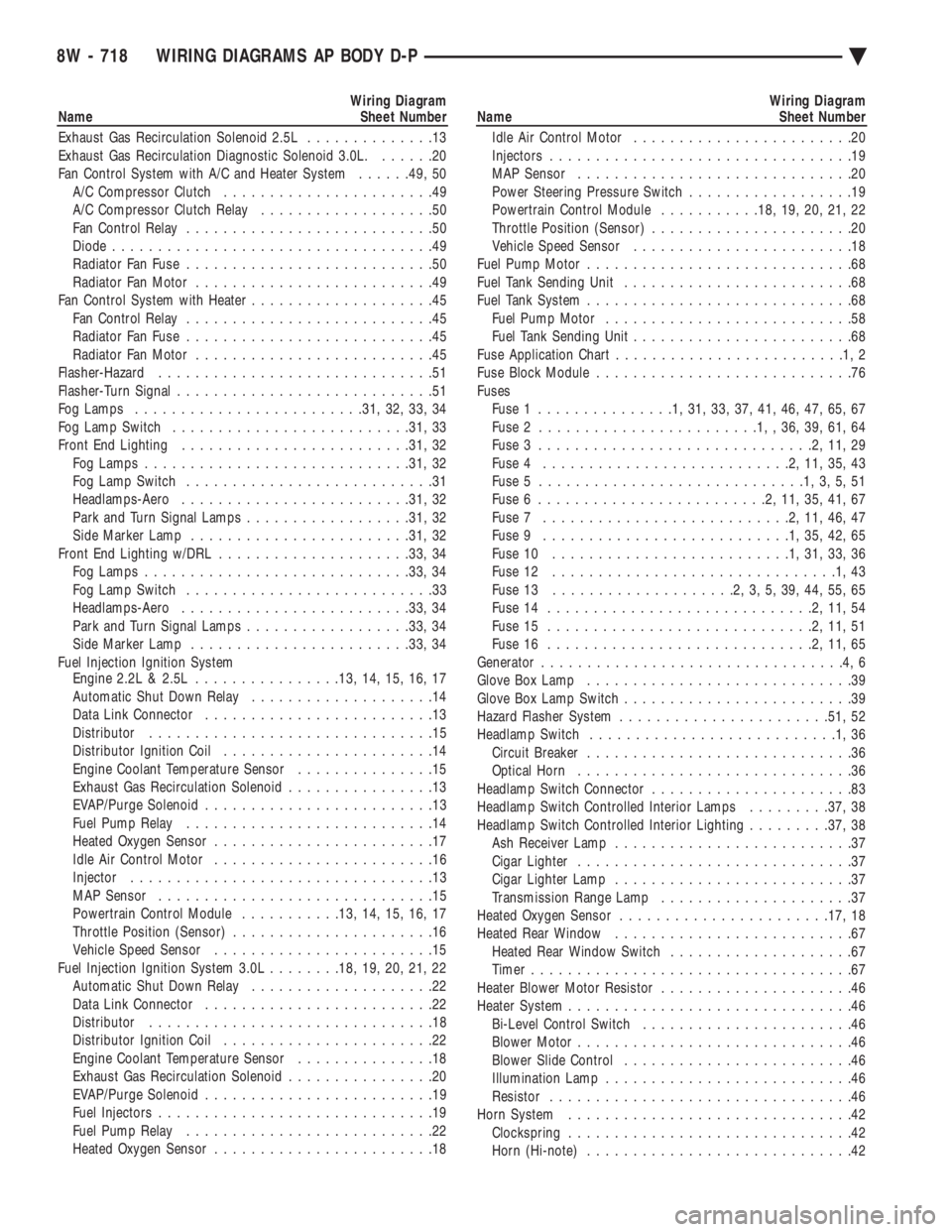
Wiring Diagram
Name Sheet Number
Exhaust Gas Recirculation Solenoid 2.5L ..............13
Exhaust Gas Recirculation Diagnostic Solenoid 3.0L. ......20
Fan Control System with A/C and Heater System ......49, 50
A/C Compressor Clutch .......................49
A/C Compressor Clutch Relay ...................50
Fan Control Relay ...........................50
Diode ...................................49
Radiator Fan Fuse ...........................50
Radiator Fan Motor ..........................49
Fan Control System with Heater ....................45
Fan Control Relay ...........................45
Radiator Fan Fuse ...........................45
Radiator Fan Motor ..........................45
Flasher-Hazard ..............................51
Flasher-Turn Signal ............................51
Fog Lamps ........................ .31, 32, 33, 34
Fog Lamp Switch ......................... .31, 33
Front End Lighting ........................ .31, 32
Fog Lamps ............................ .31, 32
Fog Lamp Switch ...........................31
Headlamps-Aero ........................ .31, 32
Park and Turn Signal Lamps ..................31, 32
Side Marker Lamp ....................... .31, 32
Front End Lighting w/DRL .................... .33, 34
Fog Lamps ............................ .33, 34
Fog Lamp Switch ...........................33
Headlamps-Aero ........................ .33, 34
Park and Turn Signal Lamps ..................33, 34
Side Marker Lamp ....................... .33, 34
Fuel Injection Ignition System Engine 2.2L & 2.5L ............... .13, 14, 15, 16, 17
Automatic Shut Down Relay ....................14
Data Link Connector .........................13
Distributor ...............................15
Distributor Ignition Coil .......................14
Engine Coolant Temperature Sensor ...............15
Exhaust Gas Recirculation Solenoid ................13
EVAP/Purge Solenoid .........................13
Fuel Pump Relay ...........................14
Heated Oxygen Sensor ........................17
Idle Air Control Motor ........................16
Injector .................................13
MAP Sensor ..............................15
Powertrain Control Module ...........13, 14, 15, 16, 17
Throttle Position (Sensor) ......................16
Vehicle Speed Sensor ........................15
Fuel Injection Ignition System 3.0L ........18, 19, 20, 21, 22
Automatic Shut Down Relay ....................22
Data Link Connector .........................22
Distributor ...............................18
Distributor Ignition Coil .......................22
Engine Coolant Temperature Sensor ...............18
Exhaust Gas Recirculation Solenoid ................20
EVAP/Purge Solenoid .........................19
Fuel Injectors ..............................19
Fuel Pump Relay ...........................22
Heated Oxygen Sensor ........................18Wiring Diagram
Name Sheet Number
Idle Air Control Motor ........................20
Injectors .................................19
MAP Sensor ..............................20
Power Steering Pressure Switch ..................19
Powertrain Control Module ...........18, 19, 20, 21, 22
Throttle Position (Sensor) ......................20
Vehicle Speed Sensor ........................18
Fuel Pump Motor .............................68
Fuel Tank Sending Unit .........................68
Fuel Tank System .............................68
Fuel Pump Motor ...........................58
Fuel Tank Sending Unit ........................68
Fuse Application Char t.........................1,2
Fuse Block Module ............................76
Fuses Fuse 1 ...............1,31,33,37,41,46,47,65,67
Fuse 2 ........................1,,36,39,61,64
Fuse 3 ..............................2,11,29
Fuse 4 ...........................2,11,35,43
Fuse 5 .............................1,3,5,51
Fuse 6 .........................2,11,35,41,67
Fuse 7 ...........................2,11,46,47
Fuse 9 ...........................1,35,42,65
Fuse 10 ..........................1,31,33,36
Fuse 12 ...............................1,43
Fuse 13 ....................2,3,5,39,44,55,65
Fuse 14 .............................2,11,54
Fuse 15 .............................2,11,51
Fuse 16 .............................2,11,65
Generator .................................4,6
Glove Box Lamp .............................39
Glove Box Lamp Switch .........................39
Hazard Flasher System ...................... .51, 52
Headlamp Switch ...........................1,36
Circuit Breaker .............................36
Optical Horn ..............................36
Headlamp Switch Connector ......................83
Headlamp Switch Controlled Interior Lamps .........37, 38
Headlamp Switch Controlled Interior Lighting .........37, 38
Ash Receiver Lamp ..........................37
Cigar Lighter ..............................37
Cigar Lighter Lamp ..........................37
Transmission Range Lamp .....................37
Heated Oxygen Sensor ...................... .17, 18
Heated Rear Window ..........................67
Heated Rear Window Switch ....................67
Timer ...................................67
Heater Blower Motor Resistor .....................46
Heater System ...............................46
Bi-Level Control Switch .......................46
Blower Motor ..............................46
Blower Slide Control .........................46
Illumination Lamp ...........................46
Resistor .................................46
Horn System ...............................42
Clockspring ...............................42
Horn (Hi-note) .............................42
8W - 718 WIRING DIAGRAMS AP BODY D-P Ä
Page 1667 of 2438
(2) Loosen the right engine mount insulator yoke
screw and 2 turns on yoke nut, then loosen the front
engine mount bracket to front crossmember screws and
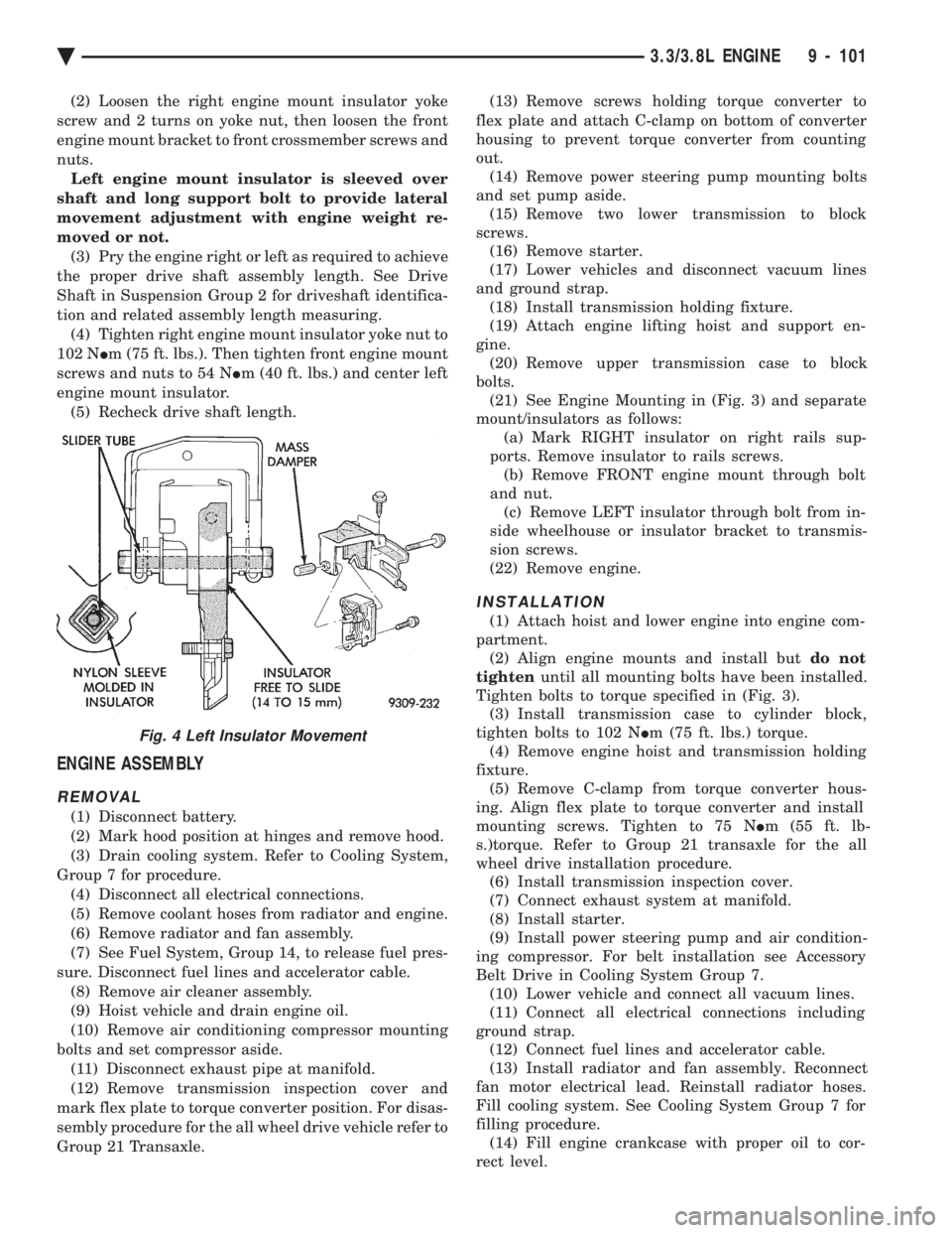
nuts. Left engine mount insulator is sleeved over
shaft and long support bolt to provide lateral
movement adjustment with engine weight re-
moved or not. (3) Pry the engine right or left as required to achieve
the proper drive shaft assembly length. See Drive
Shaft in Suspension Group 2 for driveshaft identifica-
tion and related assembly length measuring. (4) Tighten right engine mount insulator yoke nut to
102 N Im (75 ft. lbs.). Then tighten front engine mount
screws and nuts to 54 N Im (40 ft. lbs.) and center left
engine mount insulator. (5) Recheck drive shaft length.
ENGINE ASSEMBLY
REMOVAL
(1) Disconnect battery.
(2) Mark hood position at hinges and remove hood.
(3) Drain cooling system. Refer to Cooling System,
Group 7 for procedure. (4) Disconnect all electrical connections.
(5) Remove coolant hoses from radiator and engine.
(6) Remove radiator and fan assembly.
(7) See Fuel System, Group 14, to release fuel pres-
sure. Disconnect fuel lines and accelerator cable. (8) Remove air cleaner assembly.
(9) Hoist vehicle and drain engine oil.
(10) Remove air conditioning compressor mounting
bolts and set compressor aside. (11) Disconnect exhaust pipe at manifold.
(12) Remove transmission inspection cover and
mark flex plate to torque converter position. For disas-
sembly procedure for the all wheel drive vehicle refer to
Group 21 Transaxle. (13) Remove screws holding torque converter to
flex plate and attach C-clamp on bottom of converter
housing to prevent torque converter from counting
out. (14) Remove power steering pump mounting bolts
and set pump aside. (15) Remove two lower transmission to block
screws. (16) Remove starter.
(17) Lower vehicles and disconnect vacuum lines
and ground strap. (18) Install transmission holding fixture.
(19) Attach engine lifting hoist and support en-
gine. (20) Remove upper transmission case to block
bolts. (21) See Engine Mounting in (Fig. 3) and separate
mount/insulators as follows: (a) Mark RIGHT insulator on right rails sup-
ports. Remove insulator to rails screws. (b) Remove FRONT engine mount through bolt
and nut. (c) Remove LEFT insulator through bolt from in-
side wheelhouse or insulator bracket to transmis-
sion screws.
(22) Remove engine.
INSTALLATION
(1) Attach hoist and lower engine into engine com-
partment. (2) Align engine mounts and install but do not
tighten until all mounting bolts have been installed.
Tighten bolts to torque specified in (Fig. 3). (3) Install transmission case to cylinder block,
tighten bolts to 102 N Im (75 ft. lbs.) torque.
(4) Remove engine hoist and transmission holding
fixture. (5) Remove C-clamp from torque converter hous-
ing. Align flex plate to torque converter and install
mounting screws. Tighten to 75 N Im (55 ft. lb-
s.)torque. Refer to Group 21 transaxle for the all
wheel drive installation procedure. (6) Install transmission inspection cover.
(7) Connect exhaust system at manifold.
(8) Install starter.
(9) Install power steering pump and air condition-
ing compressor. For belt installation see Accessory
Belt Drive in Cooling System Group 7. (10) Lower vehicle and connect all vacuum lines.
(11) Connect all electrical connections including
ground strap. (12) Connect fuel lines and accelerator cable.
(13) Install radiator and fan assembly. Reconnect
fan motor electrical lead. Reinstall radiator hoses.
Fill cooling system. See Cooling System Group 7 for
filling procedure. (14) Fill engine crankcase with proper oil to cor-
rect level.
Fig. 4 Left Insulator Movement
Ä 3.3/3.8L ENGINE 9 - 101