fuse diagram CHEVROLET DYNASTY 1993 Owner's Manual
[x] Cancel search | Manufacturer: CHEVROLET, Model Year: 1993, Model line: DYNASTY, Model: CHEVROLET DYNASTY 1993Pages: 2438, PDF Size: 74.98 MB
Page 1289 of 2438
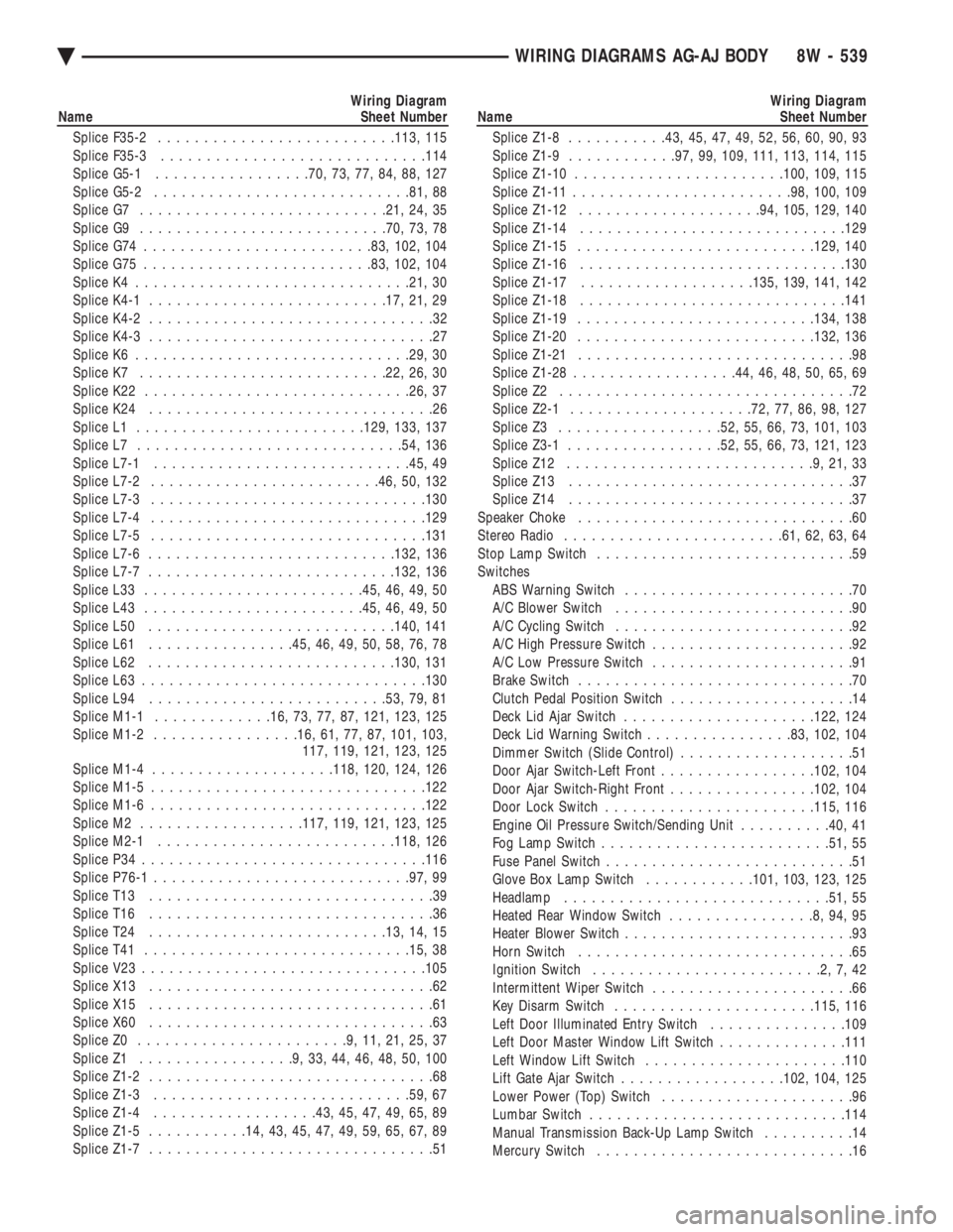
Wiring Diagram
Name Sheet Number
Splice F35-2 ......................... .113, 115
Splice F35-3 ............................ .114
Splice G5-1 ................ .70, 73, 77, 84, 88, 127
Splice G5-2 ........................... .81, 88
Splice G7 .......................... .21, 24, 35
Splice G9 .......................... .70, 73, 78
Splice G74 ........................ .83, 102, 104
Splice G75 ........................ .83, 102, 104
Splice K4 ............................. .21, 30
Splice K4-1 ......................... .17, 21, 29
Splice K4-2 ...............................32
Splice K4-3 ...............................27
Splice K6 ............................. .29, 30
Splice K7 .......................... .22, 26, 30
Splice K22 ............................ .26, 37
Splice K24 ...............................26
Splice L1 ........................ .129, 133, 137
Splice L7 ............................ .54, 136
Splice L7-1 ........................... .45, 49
Splice L7-2 ........................ .46, 50, 132
Splice L7-3 ............................. .130
Splice L7-4 ............................. .129
Splice L7-5 ............................. .131
Splice L7-6 .......................... .132, 136
Splice L7-7 .......................... .132, 136
Splice L33 ....................... .45, 46, 49, 50
Splice L43 ....................... .45, 46, 49, 50
Splice L50 .......................... .140, 141
Splice L61 ............... .45, 46, 49, 50, 58, 76, 78
Splice L62 .......................... .130, 131
Splice L63 .............................. .130
Splice L94 ......................... .53, 79, 81
Splice M1-1 ............ .16, 73, 77, 87, 121, 123, 125
Splice M1-2 ............... .16, 61, 77, 87, 101, 103,
117, 119, 121, 123, 125
Splice M1-4 ................... .118, 120, 124, 126
Splice M1-5 ............................. .122
Splice M1-6 ............................. .122
Splice M2 ................. .117, 119, 121, 123, 125
Splice M2-1 ......................... .118, 126
Splice P34 .............................. .116
Splice P76-1 ........................... .97, 99
Splice T13 ...............................39
Splice T16 ...............................36
Splice T24 ......................... .13, 14, 15
Splice T41 ............................ .15, 38
Splice V23 .............................. .105
Splice X13 ...............................62
Splice X15 ...............................61
Splice X60 ...............................63
Splice Z0 .......................9,11,21,25,37
Splice Z1 .................9,33,44,46,48,50,100
Splice Z1-2 ...............................68
Splice Z1-3 ........................... .59, 67
Splice Z1-4 ................. .43, 45, 47, 49, 65, 89
Splice Z1-5 .......... .14, 43, 45, 47, 49, 59, 65, 67, 89
Splice Z1-7 ...............................51Wiring Diagram
Name Sheet Number
Splice Z1-8 .......... .43, 45, 47, 49, 52, 56, 60, 90, 93
Splice Z1-9 ........... .97, 99, 109, 111, 113, 114, 115
Splice Z1-10 ...................... .100, 109, 115
Splice Z1-11 ....................... .98, 100, 109
Splice Z1-12 ................... .94, 105, 129, 140
Splice Z1-14 ............................ .129
Splice Z1-15 ......................... .129, 140
Splice Z1-16 ............................ .130
Splice Z1-17 .................. .135, 139, 141, 142
Splice Z1-18 ............................ .141
Splice Z1-19 ......................... .134, 138
Splice Z1-20 ......................... .132, 136
Splice Z1-21 ..............................98
Splice Z1-28 ................. .44, 46, 48, 50, 65, 69
Splice Z2 ................................72
Splice Z2-1 ................... .72, 77, 86, 98, 127
Splice Z3 ................. .52, 55, 66, 73, 101, 103
Splice Z3-1 ................ .52, 55, 66, 73, 121, 123
Splice Z12 ...........................9,21,33
Splice Z13 ...............................37
Splice Z14 ...............................37
Speaker Choke ..............................60
Stereo Radio ....................... .61, 62, 63, 64
Stop Lamp Switch ............................59
Switches ABS Warning Switch .........................70
A/C Blower Switch ..........................90
A/C Cycling Switch ..........................92
A/C High Pressure Switch ......................92
A/C Low Pressure Switch ......................91
Brake Switch ..............................70
Clutch Pedal Position Switch ....................14
Deck Lid Ajar Switch .................... .122, 124
Deck Lid Warning Switch ................83, 102, 104
Dimmer Switch (Slide Control) ...................51
Door Ajar Switch-Left Front .................102, 104
Door Ajar Switch-Right Front ................102, 104
Door Lock Switch ...................... .115, 116
Engine Oil Pressure Switch/Sending Unit ..........40, 41
Fog Lamp Switch ........................ .51, 55
Fuse Panel Switch ...........................51
Glove Box Lamp Switch ............101, 103, 123, 125
Headlamp ............................ .51, 55
Heated Rear Window Switch ................8,94,95
Heater Blower Switch .........................93
Horn Switch ..............................65
Ignition Switch .........................2,7,42
Intermittent Wiper Switch ......................66
Key Disarm Switch ..................... .115, 116
Left Door Illuminated Entry Switch ...............109
Left Door Master Window Lift Switch ..............111
Left Window Lift Switch ..................... .110
Lift Gate Ajar Switch ................. .102, 104, 125
Lower Power (Top) Switch .....................96
Lumbar Switch ........................... .114
Manual Transmission Back-Up Lamp Switch ..........14
Mercury Switch ............................16
Ä WIRING DIAGRAMS AG-AJ BODY 8W - 539
Page 1468 of 2438
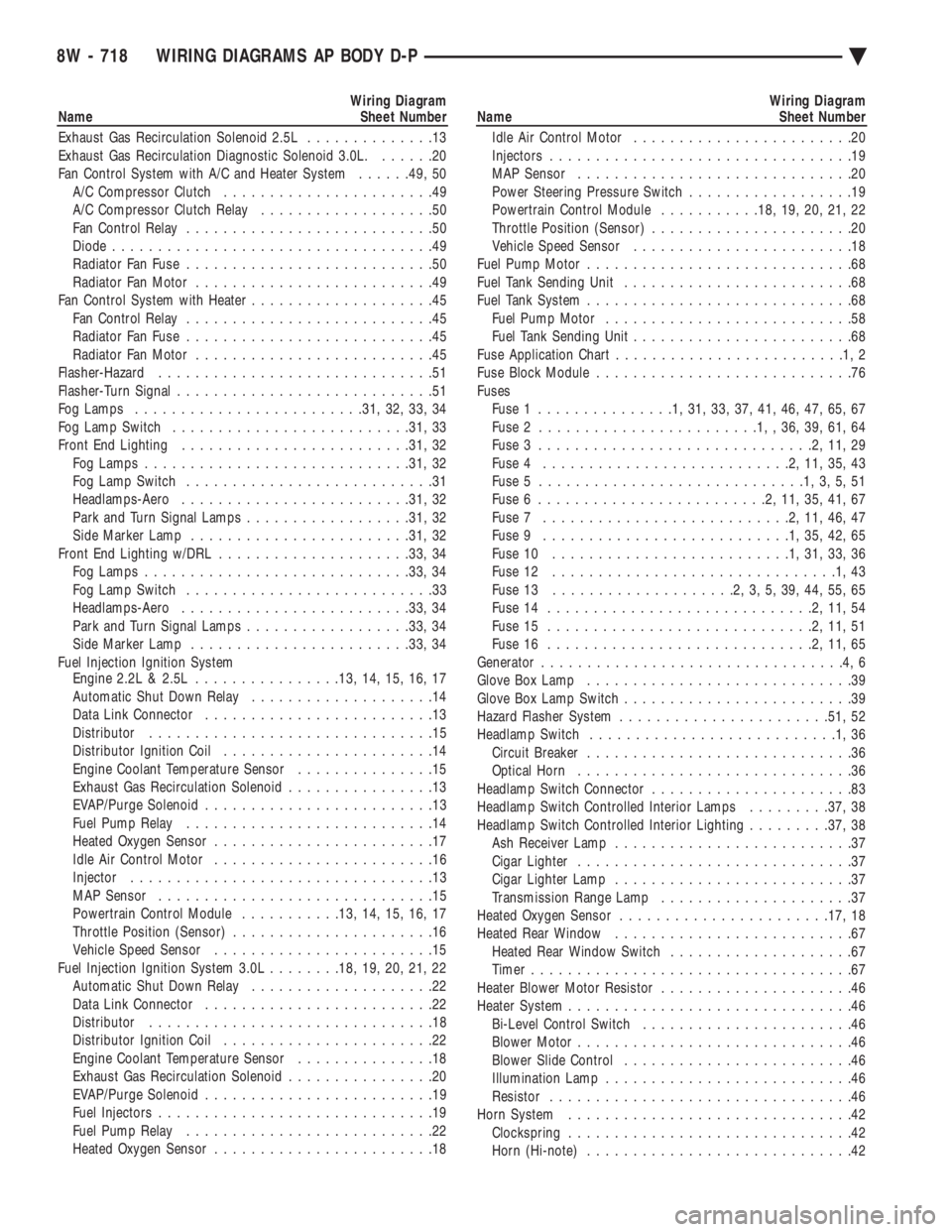
Wiring Diagram
Name Sheet Number
Exhaust Gas Recirculation Solenoid 2.5L ..............13
Exhaust Gas Recirculation Diagnostic Solenoid 3.0L. ......20
Fan Control System with A/C and Heater System ......49, 50
A/C Compressor Clutch .......................49
A/C Compressor Clutch Relay ...................50
Fan Control Relay ...........................50
Diode ...................................49
Radiator Fan Fuse ...........................50
Radiator Fan Motor ..........................49
Fan Control System with Heater ....................45
Fan Control Relay ...........................45
Radiator Fan Fuse ...........................45
Radiator Fan Motor ..........................45
Flasher-Hazard ..............................51
Flasher-Turn Signal ............................51
Fog Lamps ........................ .31, 32, 33, 34
Fog Lamp Switch ......................... .31, 33
Front End Lighting ........................ .31, 32
Fog Lamps ............................ .31, 32
Fog Lamp Switch ...........................31
Headlamps-Aero ........................ .31, 32
Park and Turn Signal Lamps ..................31, 32
Side Marker Lamp ....................... .31, 32
Front End Lighting w/DRL .................... .33, 34
Fog Lamps ............................ .33, 34
Fog Lamp Switch ...........................33
Headlamps-Aero ........................ .33, 34
Park and Turn Signal Lamps ..................33, 34
Side Marker Lamp ....................... .33, 34
Fuel Injection Ignition System Engine 2.2L & 2.5L ............... .13, 14, 15, 16, 17
Automatic Shut Down Relay ....................14
Data Link Connector .........................13
Distributor ...............................15
Distributor Ignition Coil .......................14
Engine Coolant Temperature Sensor ...............15
Exhaust Gas Recirculation Solenoid ................13
EVAP/Purge Solenoid .........................13
Fuel Pump Relay ...........................14
Heated Oxygen Sensor ........................17
Idle Air Control Motor ........................16
Injector .................................13
MAP Sensor ..............................15
Powertrain Control Module ...........13, 14, 15, 16, 17
Throttle Position (Sensor) ......................16
Vehicle Speed Sensor ........................15
Fuel Injection Ignition System 3.0L ........18, 19, 20, 21, 22
Automatic Shut Down Relay ....................22
Data Link Connector .........................22
Distributor ...............................18
Distributor Ignition Coil .......................22
Engine Coolant Temperature Sensor ...............18
Exhaust Gas Recirculation Solenoid ................20
EVAP/Purge Solenoid .........................19
Fuel Injectors ..............................19
Fuel Pump Relay ...........................22
Heated Oxygen Sensor ........................18Wiring Diagram
Name Sheet Number
Idle Air Control Motor ........................20
Injectors .................................19
MAP Sensor ..............................20
Power Steering Pressure Switch ..................19
Powertrain Control Module ...........18, 19, 20, 21, 22
Throttle Position (Sensor) ......................20
Vehicle Speed Sensor ........................18
Fuel Pump Motor .............................68
Fuel Tank Sending Unit .........................68
Fuel Tank System .............................68
Fuel Pump Motor ...........................58
Fuel Tank Sending Unit ........................68
Fuse Application Char t.........................1,2
Fuse Block Module ............................76
Fuses Fuse 1 ...............1,31,33,37,41,46,47,65,67
Fuse 2 ........................1,,36,39,61,64
Fuse 3 ..............................2,11,29
Fuse 4 ...........................2,11,35,43
Fuse 5 .............................1,3,5,51
Fuse 6 .........................2,11,35,41,67
Fuse 7 ...........................2,11,46,47
Fuse 9 ...........................1,35,42,65
Fuse 10 ..........................1,31,33,36
Fuse 12 ...............................1,43
Fuse 13 ....................2,3,5,39,44,55,65
Fuse 14 .............................2,11,54
Fuse 15 .............................2,11,51
Fuse 16 .............................2,11,65
Generator .................................4,6
Glove Box Lamp .............................39
Glove Box Lamp Switch .........................39
Hazard Flasher System ...................... .51, 52
Headlamp Switch ...........................1,36
Circuit Breaker .............................36
Optical Horn ..............................36
Headlamp Switch Connector ......................83
Headlamp Switch Controlled Interior Lamps .........37, 38
Headlamp Switch Controlled Interior Lighting .........37, 38
Ash Receiver Lamp ..........................37
Cigar Lighter ..............................37
Cigar Lighter Lamp ..........................37
Transmission Range Lamp .....................37
Heated Oxygen Sensor ...................... .17, 18
Heated Rear Window ..........................67
Heated Rear Window Switch ....................67
Timer ...................................67
Heater Blower Motor Resistor .....................46
Heater System ...............................46
Bi-Level Control Switch .......................46
Blower Motor ..............................46
Blower Slide Control .........................46
Illumination Lamp ...........................46
Resistor .................................46
Horn System ...............................42
Clockspring ...............................42
Horn (Hi-note) .............................42
8W - 718 WIRING DIAGRAMS AP BODY D-P Ä
Page 1469 of 2438
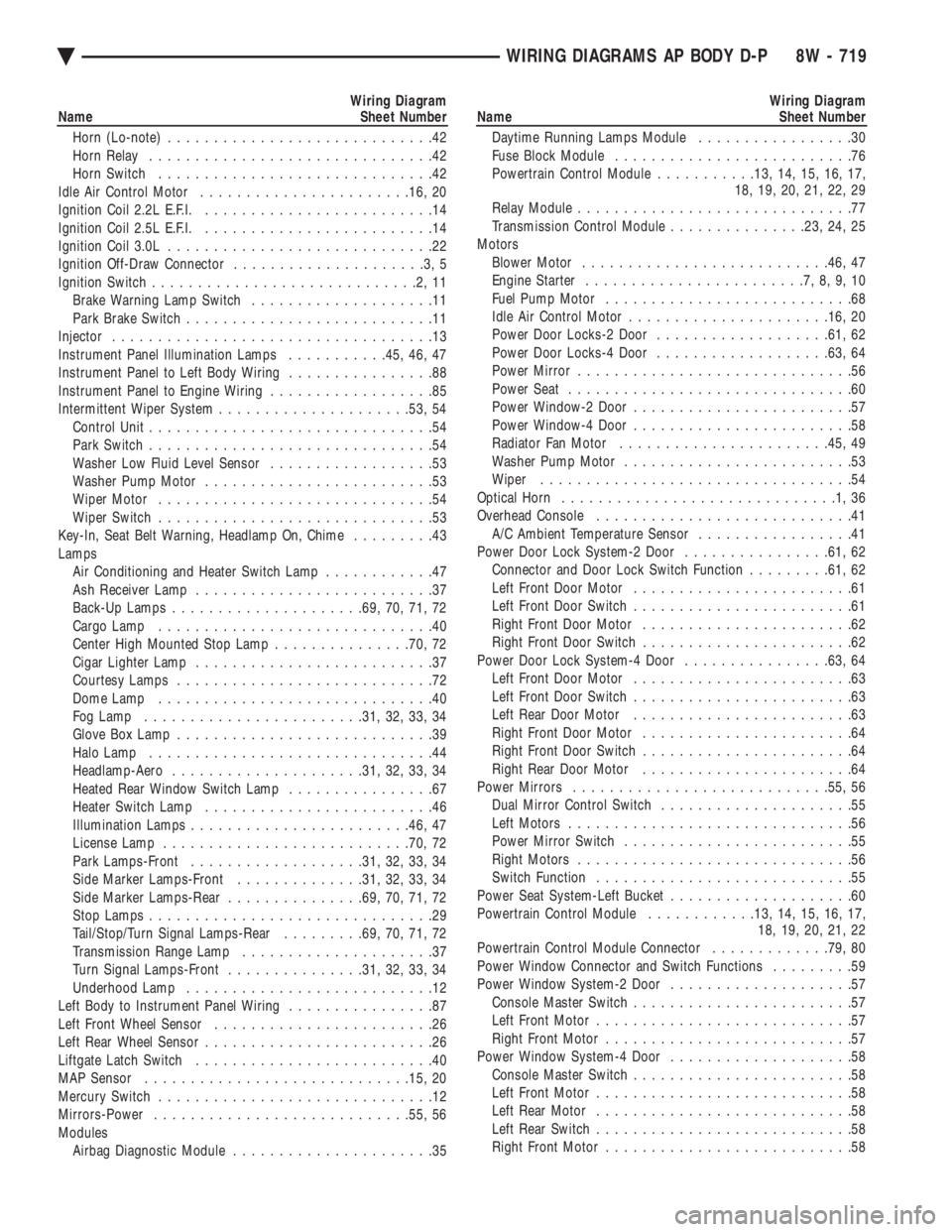
Wiring Diagram
Name Sheet Number
Horn (Lo-note) .............................42
Horn Relay ...............................42
Horn Switch ..............................42
Idle Air Control Motor ...................... .16, 20
Ignition Coil 2.2L E.F.I. .........................14
Ignition Coil 2.5L E.F.I. .........................14
Ignition Coil 3.0L .............................22
Ignition Off-Draw Connector .....................3,5
Ignition Switch .............................2,11
Brake Warning Lamp Switch ....................11
Park Brake Switch ...........................11
Injector ...................................13
Instrument Panel Illumination Lamps ...........45, 46, 47
Instrument Panel to Left Body Wiring ................88
Instrument Panel to Engine Wiring ..................85
Intermittent Wiper System .................... .53, 54
Control Unit ...............................54
Park Switch ...............................54
Washer Low Fluid Level Sensor ..................53
Washer Pump Motor .........................53
Wiper Motor ..............................54
Wiper Switch ..............................53
Key-In, Seat Belt Warning, Headlamp On, Chime .........43
Lamps Air Conditioning and Heater Switch Lamp ............47
Ash Receiver Lamp ..........................37
Back-Up Lamps .................... .69, 70, 71, 72
Cargo Lamp ..............................40
Center High Mounted Stop Lamp ...............70, 72
Cigar Lighter Lamp ..........................37
Courtesy Lamps ............................72
Dome Lamp ..............................40
Fog Lamp ....................... .31, 32, 33, 34
Glove Box Lamp ............................39
Halo Lamp ...............................44
Headlamp-Aero .................... .31, 32, 33, 34
Heated Rear Window Switch Lamp ................67
Heater Switch Lamp .........................46
Illumination Lamps ....................... .46, 47
License Lamp .......................... .70, 72
Park Lamps-Front .................. .31, 32, 33, 34
Side Marker Lamps-Front ..............31, 32, 33, 34
Side Marker Lamps-Rear ...............69, 70, 71, 72
Stop Lamps ...............................29
Tail/Stop/Turn Signal Lamps-Rear .........69, 70, 71, 72
Transmission Range Lamp .....................37
Turn Signal Lamps-Front ...............31, 32, 33, 34
Underhood Lamp ...........................12
Left Body to Instrument Panel Wiring ................87
Left Front Wheel Sensor ........................26
Left Rear Wheel Sensor .........................26
Liftgate Latch Switch ..........................40
MAP Sensor ............................ .15, 20
Mercury Switch ..............................12
Mirrors-Power ........................... .55, 56
Modules Airbag Diagnostic Module ......................35Wiring Diagram
Name Sheet Number
Daytime Running Lamps Module .................30
Fuse Block Module ..........................76
Powertrain Control Module ...........13, 14, 15, 16, 17,
18, 19, 20, 21, 22, 29
Relay Module ..............................77
Transmission Control Module ...............23, 24, 25
Motors Blower Motor .......................... .46, 47
Engine Starter ........................7,8,9,10
Fuel Pump Motor ...........................68
Idle Air Control Motor ..................... .16, 20
Power Door Locks-2 Door .................. .61, 62
Power Door Locks-4 Door .................. .63, 64
Power Mirror ..............................56
Power Seat ...............................60
Power Window-2 Door ........................57
Power Window-4 Door ........................58
Radiator Fan Motor ...................... .45, 49
Washer Pump Motor .........................53
Wiper ..................................54
Optical Horn ..............................1,36
Overhead Console ............................41
A/C Ambient Temperature Sensor .................41
Power Door Lock System-2 Door ................61, 62
Connector and Door Lock Switch Function .........61, 62
Left Front Door Motor ........................61
Left Front Door Switch ........................61
Right Front Door Motor .......................62
Right Front Door Switch .......................62
Power Door Lock System-4 Door ................63, 64
Left Front Door Motor ........................63
Left Front Door Switch ........................63
Left Rear Door Motor ........................63
Right Front Door Motor .......................64
Right Front Door Switch .......................64
Right Rear Door Motor .......................64
Power Mirrors ........................... .55, 56
Dual Mirror Control Switch .....................55
Left Motors ...............................56
Power Mirror Switch .........................55
Right Motors ..............................56
Switch Function ............................55
Power Seat System-Left Bucket ....................60
Powertrain Control Module ............13, 14, 15, 16, 17,
18, 19, 20, 21, 22
Powertrain Control Module Connector .............79, 80
Power Window Connector and Switch Functions .........59
Power Window System-2 Door ....................57
Console Master Switch ........................57
Left Front Motor ............................57
Right Front Motor ...........................57
Power Window System-4 Door ....................58
Console Master Switch ........................58
Left Front Motor ............................58
Left Rear Motor ............................58
Left Rear Switch ............................58
Right Front Motor ...........................58
Ä WIRING DIAGRAMS AP BODY D-P 8W - 719
Page 1470 of 2438
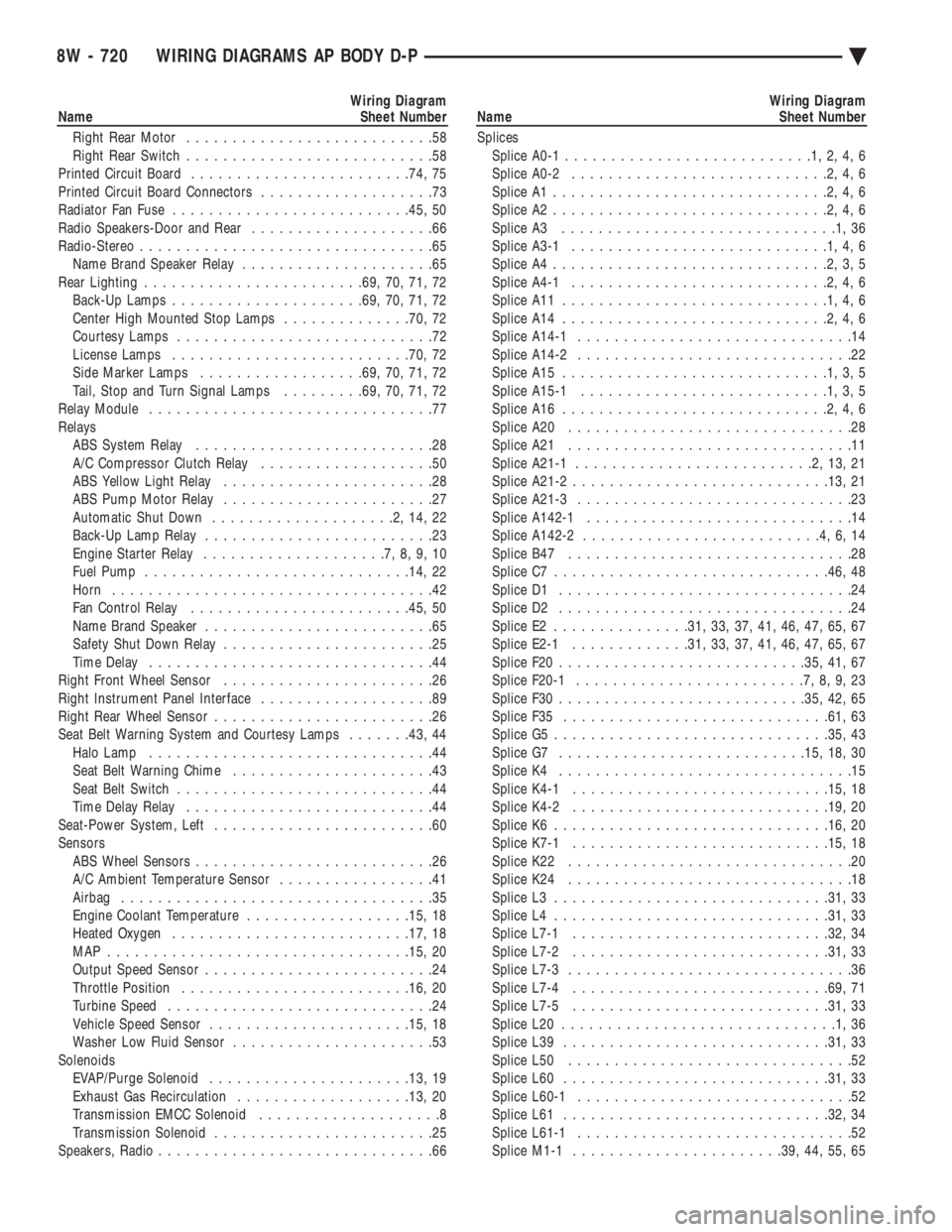
Wiring Diagram
Name Sheet Number
Right Rear Motor ...........................58
Right Rear Switch ...........................58
Printed Circuit Board ....................... .74, 75
Printed Circuit Board Connectors ...................73
Radiator Fan Fuse ......................... .45, 50
Radio Speakers-Door and Rear ....................66
Radio-Stereo ................................65
Name Brand Speaker Relay .....................65
Rear Lighting ....................... .69, 70, 71, 72
Back-Up Lamps .................... .69, 70, 71, 72
Center High Mounted Stop Lamps ..............70, 72
Courtesy Lamps ............................72
License Lamps ......................... .70, 72
Side Marker Lamps ................. .69, 70, 71, 72
Tail, Stop and Turn Signal Lamps .........69, 70, 71, 72
Relay Module ...............................77
Relays ABS System Relay ..........................28
A/C Compressor Clutch Relay ...................50
ABS Yellow Light Relay .......................28
ABS Pump Motor Relay .......................27
Automatic Shut Down ....................2,14,22
Back-Up Lamp Relay .........................23
Engine Starter Relay ....................7,8,9,10
Fuel Pump ............................ .14, 22
Horn ...................................42
Fan Control Relay ....................... .45, 50
Name Brand Speaker .........................65
Safety Shut Down Relay .......................25
Time Delay ...............................44
Right Front Wheel Sensor .......................26
Right Instrument Panel Interface ...................89
Right Rear Wheel Sensor ........................26
Seat Belt Warning System and Courtesy Lamps .......43, 44
Halo Lamp ...............................44
Seat Belt Warning Chime ......................43
Seat Belt Switch ............................44
Time Delay Relay ...........................44
Seat-Power System, Left ........................60
Sensors ABS Wheel Sensors ..........................26
A/C Ambient Temperature Sensor .................41
Airbag ..................................35
Engine Coolant Temperature ..................15, 18
Heated Oxygen ......................... .17, 18
MAP ................................ .15, 20
Output Speed Sensor .........................24
Throttle Position ........................ .16, 20
Turbine Speed .............................24
Vehicle Speed Sensor ..................... .15, 18
Washer Low Fluid Sensor ......................53
Solenoids EVAP/Purge Solenoid ..................... .13, 19
Exhaust Gas Recirculation .................. .13, 20
Transmission EMCC Solenoid ....................8
Transmission Solenoid ........................25
Speakers, Radio ..............................66Wiring Diagram
Name Sheet Number
Splices Splice A0-1 ...........................1,2,4,6
Splice A0-2 ............................2,4,6
Splice A1 ..............................2,4,6
Splice A2 ..............................2,4,6
Splice A3 ..............................1,36
Splice A3-1 ............................1,4,6
Splice A4 ..............................2,3,5
Splice A4-1 ............................2,4,6
Splice A11 .............................1,4,6
Splice A14 .............................2,4,6
Splice A14-1 ..............................14
Splice A14-2 ..............................22
Splice A15 .............................1,3,5
Splice A15-1 ...........................1,3,5
Splice A16 .............................2,4,6
Splice A20 ...............................28
Splice A21 ...............................11
Splice A21-1 ..........................2,13,21
Splice A21-2 ........................... .13, 21
Splice A21-3 ..............................23
Splice A142-1 .............................14
Splice A142-2 ..........................4,6,14
Splice B47 ...............................28
Splice C7 ............................. .46, 48
Splice D1 ................................24
Splice D2 ................................24
Splice E2 .............. .31, 33, 37, 41, 46, 47, 65, 67
Splice E2-1 ............ .31, 33, 37, 41, 46, 47, 65, 67
Splice F20 .......................... .35, 41, 67
Splice F20-1 .........................7,8,9,23
Splice F30 .......................... .35, 42, 65
Splice F35 ............................ .61, 63
Splice G5 ............................. .35, 43
Splice G7 .......................... .15, 18, 30
Splice K4 ................................15
Splice K4-1 ........................... .15, 18
Splice K4-2 ........................... .19, 20
Splice K6 ............................. .16, 20
Splice K7-1 ........................... .15, 18
Splice K22 ...............................20
Splice K24 ...............................18
Splice L3 ............................. .31, 33
Splice L4 ............................. .31, 33
Splice L7-1 ........................... .32, 34
Splice L7-2 ........................... .31, 33
Splice L7-3 ...............................36
Splice L7-4 ........................... .69, 71
Splice L7-5 ........................... .31, 33
Splice L20 ..............................1,36
Splice L39 ............................ .31, 33
Splice L50 ...............................52
Splice L60 ............................ .31, 33
Splice L60-1 ..............................52
Splice L61 ............................ .32, 34
Splice L61-1 ..............................52
Splice M1-1 ...................... .39, 44, 55, 65
8W - 720 WIRING DIAGRAMS AP BODY D-P Ä
Page 2358 of 2438
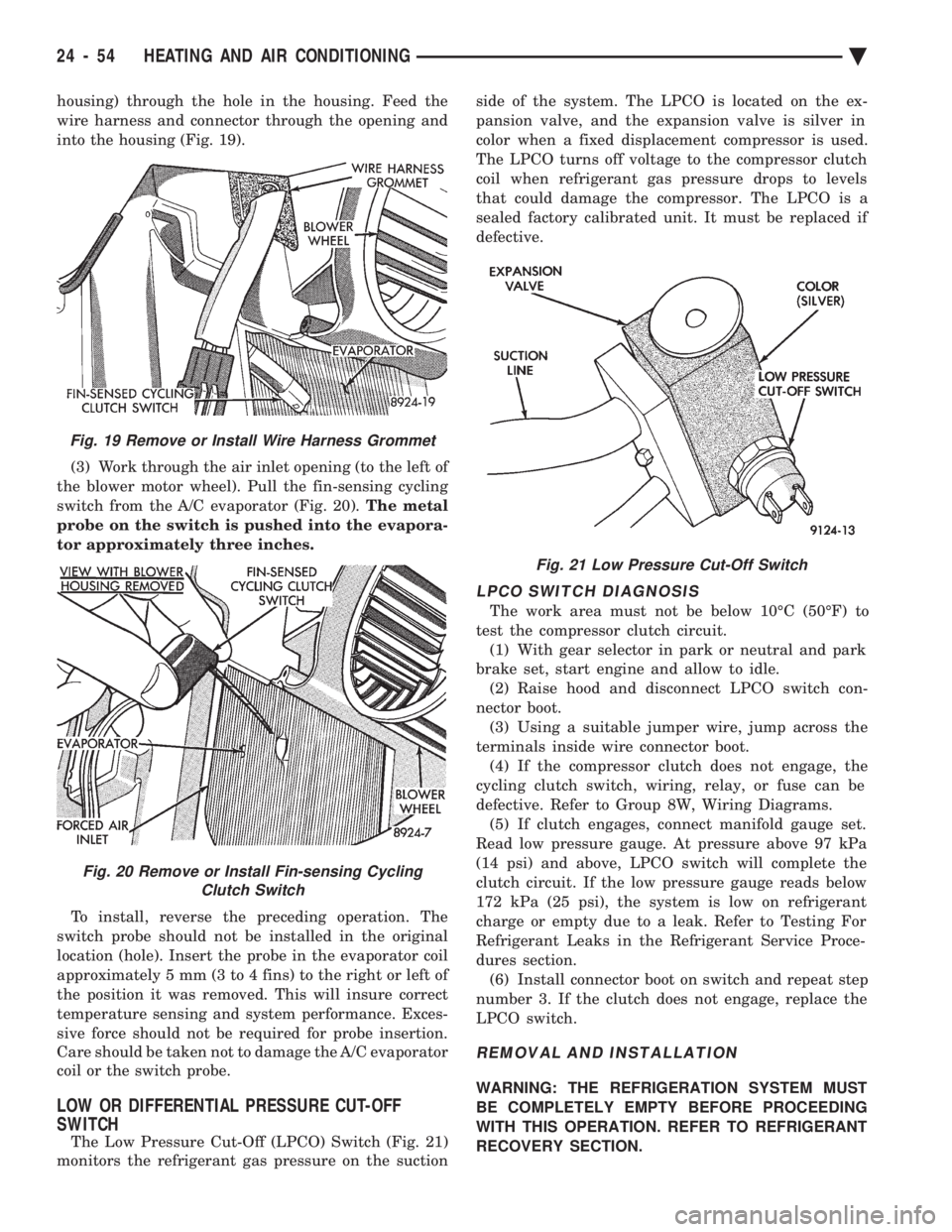
housing) through the hole in the housing. Feed the
wire harness and connector through the opening and
into the housing (Fig. 19). (3) Work through the air inlet opening (to the left of
the blower motor wheel). Pull the fin-sensing cycling
switch from the A/C evaporator (Fig. 20). The metal
probe on the switch is pushed into the evapora-
tor approximately three inches.
To install, reverse the preceding operation. The
switch probe should not be installed in the original
location (hole). Insert the probe in the evaporator coil
approximately 5 mm (3 to 4 fins) to the right or left of
the position it was removed. This will insure correct
temperature sensing and system performance. Exces-
sive force should not be required for probe insertion.
Care should be taken not to damage the A/C evaporator
coil or the switch probe.
LOW OR DIFFERENTIAL PRESSURE CUT-OFF
SWITCH
The Low Pressure Cut-Off (LPCO) Switch (Fig. 21)
monitors the refrigerant gas pressure on the suction side of the system. The LPCO is located on the ex-
pansion valve, and the expansion valve is silver in
color when a fixed displacement compressor is used.
The LPCO turns off voltage to the compressor clutch
coil when refrigerant gas pressure drops to levels
that could damage the compressor. The LPCO is a
sealed factory calibrated unit. It must be replaced if
defective.
LPCO SWITCH DIAGNOSIS
The work area must not be below 10ÉC (50ÉF) to
test the compressor clutch circuit. (1) With gear selector in park or neutral and park
brake set, start engine and allow to idle. (2) Raise hood and disconnect LPCO switch con-
nector boot. (3) Using a suitable jumper wire, jump across the
terminals inside wire connector boot. (4) If the compressor clutch does not engage, the
cycling clutch switch, wiring, relay, or fuse can be
defective. Refer to Group 8W, Wiring Diagrams. (5) If clutch engages, connect manifold gauge set.
Read low pressure gauge. At pressure above 97 kPa
(14 psi) and above, LPCO switch will complete the
clutch circuit. If the low pressure gauge reads below
172 kPa (25 psi), the system is low on refrigerant
charge or empty due to a leak. Refer to Testing For
Refrigerant Leaks in the Refrigerant Service Proce-
dures section. (6) Install connector boot on switch and repeat step
number 3. If the clutch does not engage, replace the
LPCO switch.
REMOVAL AND INSTALLATION
WARNING: THE REFRIGERATION SYSTEM MUST
BE COMPLETELY EMPTY BEFORE PROCEEDING
WITH THIS OPERATION. REFER TO REFRIGERANT
RECOVERY SECTION.
Fig. 21 Low Pressure Cut-Off Switch
Fig. 19 Remove or Install Wire Harness Grommet
Fig. 20 Remove or Install Fin-sensing Cycling Clutch Switch
24 - 54 HEATING AND AIR CONDITIONING Ä
Page 2377 of 2438
(b) Does the blower motor operate at its highest
speed ? (c) Feel the outlet temperature. Does it get hot
and then cycle cold ? (d) Does the air flow switch from DEFROST out-
lets and then cycle to PANEL outlets?
If you can answer NO to any of these questions,
proceed to step 4, otherwise proceed to step 5. (4) If you answered NO to:
SYMPTOM A
The display symbols and indicators do not illumi-
nate. Diagnostic Trouble Codes are not displayed.
TEST
After self-diagnostic test is complete, select a mode
that will display the malfunction.
ACTION
If the ATC system operates properly, and the dis-
play does not, replace ATC control panel computer.
SYMPTOM B
The blower motor does not operate.
CAUTION: Stay clear of blower motor and power
module (PM) heat sink. Do not run system for more
than 10 minutes with PM removed from A/C unit.
TEST Check all power module and blower motor connec-
tions. Use a voltmeter to test for 12 volts (ignition)
at both ends of the fuse with ignition ON. If fuse is
good, test the green wire at the blower motor connec-
tor for 12 volts (ignition) to body ground. Turn ignition to the ON position.
With the blower motor still connected, check for 12
volts to body ground on the black/tan wire of the
blower motor two way connector. Check for 12 volts at the Power Module pin #4
(BK/TN). Check for continuity from the Power Module pin
#3 (BK) to chassis ground. Replace the Power Module.
ACTION If 12 volts is not detected, repair feed circuit. Refer
to the Front Wheel Drive Car-Wiring Diagrams Ser-
vice Manual. If 12 volts is not detected, repair wires of the
blower motor or replace the blower motor. If 12 volts is not present, repair wire from the
blower motor connector to the Power Module. If circuit is open, repair ground circuit of the Power
Module. Replace the Power Module (power transistor open).
SYMPTOM C
The outlet air temperature does not become hot
and then cycle to cold during self-test operation. Di-
agnostic Trouble Codes are not displayed.
TEST/ACTION
Make sure the blend-air door is properly attached
to the actuator. If cold air is not discharged from the outlets, check
the base A/C refrigerant system. Make sure heating operation works correctly, (wa-
ter level, thermostat, heater hoses, heater core, etc.).
SYMPTOM D
Air does not flow from DEFROST outlets and then
cycle to PANEL outlets during self-test operation.
TEST/ACTION Check linkages from the mode door actuator for
binding. Check for proper door travel in the unit.
(5) The computer will do one of two things:
² Will return to the control settings that were se-
lected before the Diagnostic Test was started. This
means the test is over. If Diagnostic Trouble Codes
did not occur, and answers to questions (a), (b), (c),
and (d) were YES, the entire system is operating cor-
rectly.
² The blower motor will stop and the computer will
flash a Diagnostic Trouble Code number from 01
through 28. Record the number and then depress the
PANEL button to advance to the next test. If the
ATC control flashes one or more codes 23 to 28, the
digits on the display will flash alternating Zeros. If
you do nothing, these codes will remain stored within
the ATC control computer. After all repairs have
been made erase fault codes. Refer to Erasing Diag-
nostic Trouble Codes 23 through 28 from ATC Con-
trol in this section. Repair all Diagnostic Trouble Codes in the order
that they have been indicated, and then retest the
system. If any blend door test fails, all remaining
blend door tests will be skipped. IF any mode door
tests fail, all remaining mode door tests will be
skipped. Diagnostic Test can be stopped at any time by de-
pressing any button other than PANEL.
DIAGNOSTIC TROUBLE CODE DEFINITIONS
Non-computer aided diagnostics should be per-
formed first. Hood of vehicle should be closed during
the diagnostic test to keep engine heat from effecting
the ambient temperature sensor. Also refer to the wiring Pin out charts.
² DIAGNOSTIC TROUBLE CODE 1
Involves the wiring or the ATC control head.
² DIAGNOSTIC TROUBLE CODES 2, 13, 14, 15,
20, and 23
Ä HEATING AND AIR CONDITIONING 24 - 73