center console CHEVROLET DYNASTY 1993 Owner's Guide
[x] Cancel search | Manufacturer: CHEVROLET, Model Year: 1993, Model line: DYNASTY, Model: CHEVROLET DYNASTY 1993Pages: 2438, PDF Size: 74.98 MB
Page 1287 of 2438
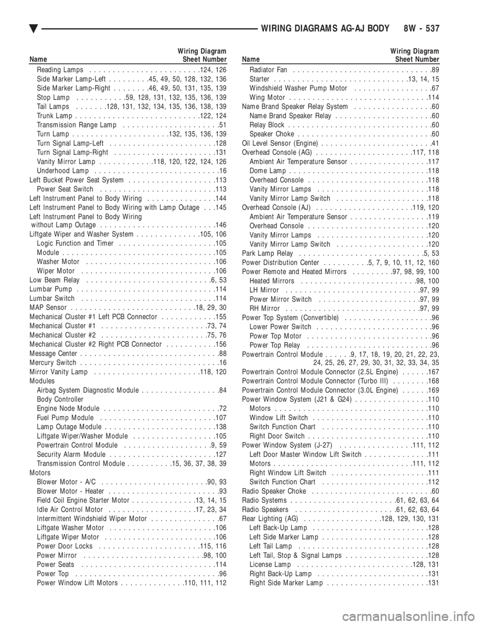
Wiring Diagram
Name Sheet Number
Reading Lamps ....................... .124, 126
Side Marker Lamp-Left .........45, 49, 50, 128, 132, 136
Side Marker Lamp-Right ........46, 49, 50, 131, 135, 139
Stop Lamp .......... .59, 128, 131, 132, 135, 136, 139
Tail Lamps .......128, 131, 132, 134, 135, 136, 138, 139
Trunk Lamp .......................... .122, 124
Transmission Range Lamp .....................51
Turn Lamp .................... .132, 135, 136, 139
Turn Signal Lamp-Left ...................... .128
Turn Signal Lamp-Right ..................... .131
Vanity Mirror Lamp ............118, 120, 122, 124, 126
Underhood Lamp ...........................16
Left Bucket Power Seat System ...................113
Power Seat Switch ........................ .113
Left Instrument Panel to Body Wiring ...............144
Left Instrument Panel to Body Wiring with Lamp Outage . . .145
Left Instrument Panel to Body Wiring without Lamp Outage ........................ .146
Liftgate Wiper and Washer System ..............105, 106
Logic Function and Timer .................... .105
Module ................................ .105
Washer Motor ........................... .106
Wiper Motor ............................ .106
Low Beam Relay ...........................6,53
Lumbar Pump ............................. .114
Lumbar Switch ............................ .114
MAP Sensor .......................... .18, 29, 30
Mechanical Cluster #1 Left PCB Connector ............155
Mechanical Cluster #1 ...................... .73, 74
Mechanical Cluster #2 ...................... .75, 76
Mechanical Cluster #2 Right PCB Connector ...........156
Message Center ..............................88
Mercury Switch ..............................16
Mirror Vanity Lamp ...................... .118, 120
Modules Airbag System Diagnostic Module .................84
Body Controller
Engine Node Module .........................72
Fuel Pump Module ........................ .107
Lamp Outage Module ....................... .138
Liftgate Wiper/Washer Module ..................105
Powertrain Control Module ...................9,59
Security Alarm Module ...................... .127
Transmission Control Module ..........15, 36, 37, 38, 39
Motors Blower Motor - A/C ...................... .90, 93
Blower Motor - Heater ........................93
Field Coil Engine Starter Motor ..............13, 14, 15
Idle Air Control Motor .................. .17, 23, 34
Intermittent Windshield Wiper Motor ...............67
Liftgate Washer Motor ...................... .106
Liftgate Wiper Motor ....................... .106
Power Door Locks ..................... .115, 116
Power Mirror ......................... .98, 100
Power Seats ............................ .114
Power Top ...............................96
Power Window Lift Motors ..............110, 111, 112Wiring Diagram
Name Sheet Number
Radiator Fan ..............................89
Starter ............................ .13, 14, 15
Windshield Washer Pump Motor .................67
Wing Motor ............................. .114
Name Brand Speaker Relay System .................60
Name Brand Speaker Relay .....................60
Relay Block ...............................60
Speaker Choke .............................60
Oil Level Sensor (Engine) ........................41
Overhead Console (AG) .................... .117, 118
Ambient Air Temperature Sensor .................117
Dome Lamp ............................. .118
Overhead Console ......................... .118
Vanity Mirror Lamps ....................... .118
Vanity Mirror Lamp Switch ................... .118
Overhead Console (AJ) .................... .119, 120
Ambient Air Temperature Sensor .................119
Overhead Console ......................... .120
Vanity Mirror Lamps ....................... .120
Vanity Mirror Lamp Switch ................... .120
Park Lamp Relay ...........................5,53
Power Distribution Center ..........5,7,9,10,11,12,160
Power Remote and Heated Mirrors .........97, 98, 99, 100
Heated Mirrors ........................ .98, 100
LH Mirror ............................ .97, 99
Power Mirror Switch ..................... .97, 99
RH Mirror ............................ .97, 99
Power Top System (Convertible) ...................96
Lower Power Switch .........................96
Power Top Motor ...........................96
Power Top Relay ...........................96
Powertrain Control Module ......9,17,18,19,20,21,22,23,
24, 25, 26, 27, 29, 30, 31, 32, 33, 34, 35
Powertrain Control Module Connector (2.5L Engine) ......167
Powertrain Control Module Connector (Turbo III) ........168
Powertrain Control Module Connector (3.0L Engine) ......169
Power Window System (J21 & G24) ................110
Motors ................................ .110
Window Lift Switch ........................ .110
Switch Function Chart ...................... .110
Right Door Switch ......................... .110
Power Window System (J-27) ................111, 112
Left Door Master Window Lift Switch ..............111
Motors ............................. .111, 112
Right Window Lift Switch .................... .111
Switch Function Chart ...................... .112
Radio Speaker Choke ..........................60
Radio Systems ...................... .61, 62, 63, 64
Radio Speakers ..................... .61, 62, 63, 64
Rear Lighting (AG) ................ .128, 129, 130, 131
Left Back-Up Lamp ........................ .128
Left Side Marker Lamp ...................... .128
Left Tail Lamp ........................... .128
Left Tail, Stop & Signal Lamps ..................128
License Lamp ........................ .128, 131
Right Back-Up Lamp ....................... .131
Right Side Marker Lamp ..................... .131
Ä WIRING DIAGRAMS AG-AJ BODY 8W - 537
Page 1469 of 2438
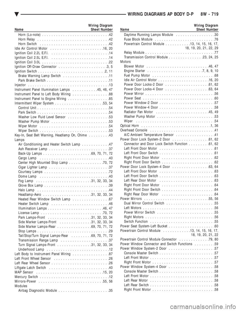
Wiring Diagram
Name Sheet Number
Horn (Lo-note) .............................42
Horn Relay ...............................42
Horn Switch ..............................42
Idle Air Control Motor ...................... .16, 20
Ignition Coil 2.2L E.F.I. .........................14
Ignition Coil 2.5L E.F.I. .........................14
Ignition Coil 3.0L .............................22
Ignition Off-Draw Connector .....................3,5
Ignition Switch .............................2,11
Brake Warning Lamp Switch ....................11
Park Brake Switch ...........................11
Injector ...................................13
Instrument Panel Illumination Lamps ...........45, 46, 47
Instrument Panel to Left Body Wiring ................88
Instrument Panel to Engine Wiring ..................85
Intermittent Wiper System .................... .53, 54
Control Unit ...............................54
Park Switch ...............................54
Washer Low Fluid Level Sensor ..................53
Washer Pump Motor .........................53
Wiper Motor ..............................54
Wiper Switch ..............................53
Key-In, Seat Belt Warning, Headlamp On, Chime .........43
Lamps Air Conditioning and Heater Switch Lamp ............47
Ash Receiver Lamp ..........................37
Back-Up Lamps .................... .69, 70, 71, 72
Cargo Lamp ..............................40
Center High Mounted Stop Lamp ...............70, 72
Cigar Lighter Lamp ..........................37
Courtesy Lamps ............................72
Dome Lamp ..............................40
Fog Lamp ....................... .31, 32, 33, 34
Glove Box Lamp ............................39
Halo Lamp ...............................44
Headlamp-Aero .................... .31, 32, 33, 34
Heated Rear Window Switch Lamp ................67
Heater Switch Lamp .........................46
Illumination Lamps ....................... .46, 47
License Lamp .......................... .70, 72
Park Lamps-Front .................. .31, 32, 33, 34
Side Marker Lamps-Front ..............31, 32, 33, 34
Side Marker Lamps-Rear ...............69, 70, 71, 72
Stop Lamps ...............................29
Tail/Stop/Turn Signal Lamps-Rear .........69, 70, 71, 72
Transmission Range Lamp .....................37
Turn Signal Lamps-Front ...............31, 32, 33, 34
Underhood Lamp ...........................12
Left Body to Instrument Panel Wiring ................87
Left Front Wheel Sensor ........................26
Left Rear Wheel Sensor .........................26
Liftgate Latch Switch ..........................40
MAP Sensor ............................ .15, 20
Mercury Switch ..............................12
Mirrors-Power ........................... .55, 56
Modules Airbag Diagnostic Module ......................35Wiring Diagram
Name Sheet Number
Daytime Running Lamps Module .................30
Fuse Block Module ..........................76
Powertrain Control Module ...........13, 14, 15, 16, 17,
18, 19, 20, 21, 22, 29
Relay Module ..............................77
Transmission Control Module ...............23, 24, 25
Motors Blower Motor .......................... .46, 47
Engine Starter ........................7,8,9,10
Fuel Pump Motor ...........................68
Idle Air Control Motor ..................... .16, 20
Power Door Locks-2 Door .................. .61, 62
Power Door Locks-4 Door .................. .63, 64
Power Mirror ..............................56
Power Seat ...............................60
Power Window-2 Door ........................57
Power Window-4 Door ........................58
Radiator Fan Motor ...................... .45, 49
Washer Pump Motor .........................53
Wiper ..................................54
Optical Horn ..............................1,36
Overhead Console ............................41
A/C Ambient Temperature Sensor .................41
Power Door Lock System-2 Door ................61, 62
Connector and Door Lock Switch Function .........61, 62
Left Front Door Motor ........................61
Left Front Door Switch ........................61
Right Front Door Motor .......................62
Right Front Door Switch .......................62
Power Door Lock System-4 Door ................63, 64
Left Front Door Motor ........................63
Left Front Door Switch ........................63
Left Rear Door Motor ........................63
Right Front Door Motor .......................64
Right Front Door Switch .......................64
Right Rear Door Motor .......................64
Power Mirrors ........................... .55, 56
Dual Mirror Control Switch .....................55
Left Motors ...............................56
Power Mirror Switch .........................55
Right Motors ..............................56
Switch Function ............................55
Power Seat System-Left Bucket ....................60
Powertrain Control Module ............13, 14, 15, 16, 17,
18, 19, 20, 21, 22
Powertrain Control Module Connector .............79, 80
Power Window Connector and Switch Functions .........59
Power Window System-2 Door ....................57
Console Master Switch ........................57
Left Front Motor ............................57
Right Front Motor ...........................57
Power Window System-4 Door ....................58
Console Master Switch ........................58
Left Front Motor ............................58
Left Rear Motor ............................58
Left Rear Switch ............................58
Right Front Motor ...........................58
Ä WIRING DIAGRAMS AP BODY D-P 8W - 719
Page 1955 of 2438
INTERLOCK SYSTEM ADJUSTMENT
If ignition switch is binding, operating effort high or
can not be turned to the LOCK position, with shifter locked
in PARK, adjustment of Interlock System may be
required. To adjust Interlock System, follow procedure
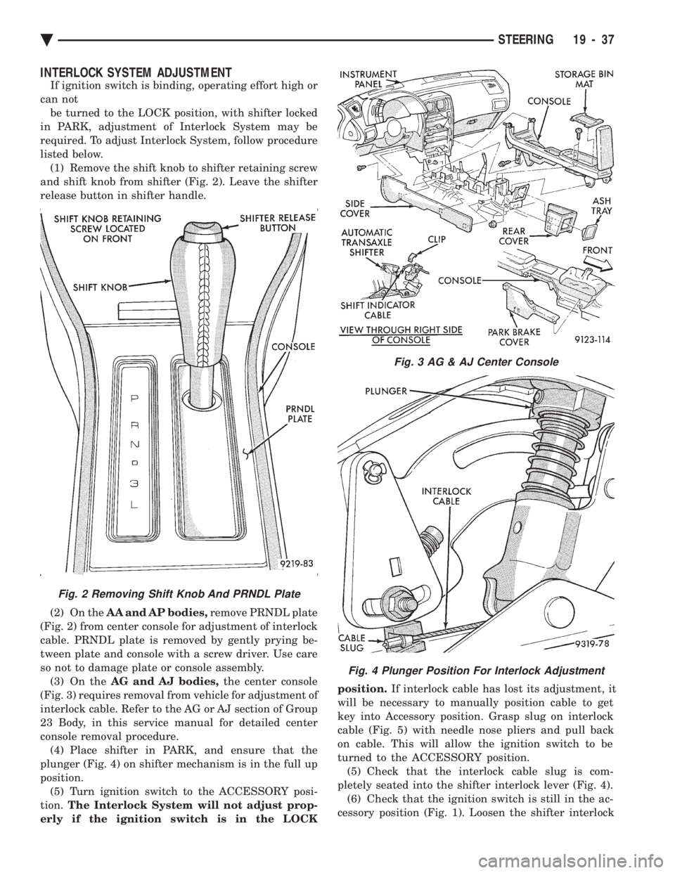
listed below. (1) Remove the shift knob to shifter retaining screw
and shift knob from shifter (Fig. 2). Leave the shifter
release button in shifter handle.
(2) On the AA and AP bodies, remove PRNDL plate
(Fig. 2) from center console for adjustment of interlock
cable. PRNDL plate is removed by gently prying be-
tween plate and console with a screw driver. Use care
so not to damage plate or console assembly. (3) On the AG and AJ bodies, the center console
(Fig. 3) requires removal from vehicle for adjustment of
interlock cable. Refer to the AG or AJ section of Group
23 Body, in this service manual for detailed center
console removal procedure. (4) Place shifter in PARK, and ensure that the
plunger (Fig. 4) on shifter mechanism is in the full up
position. (5) Turn ignition switch to the ACCESSORY posi-
tion. The Interlock System will not adjust prop-
erly if the ignition switch is in the LOCK position.
If interlock cable has lost its adjustment, it
will be necessary to manually position cable to get
key into Accessory position. Grasp slug on interlock
cable (Fig. 5) with needle nose pliers and pull back
on cable. This will allow the ignition switch to be
turned to the ACCESSORY position. (5) Check that the interlock cable slug is com-
pletely seated into the shifter interlock lever (Fig. 4). (6) Check that the ignition switch is still in the ac-
cessory position (Fig. 1). Loosen the shifter interlock
Fig. 3 AG & AJ Center Console
Fig. 4 Plunger Position For Interlock Adjustment
Fig. 2 Removing Shift Knob And PRNDL Plate
Ä STEERING 19 - 37
Page 1956 of 2438
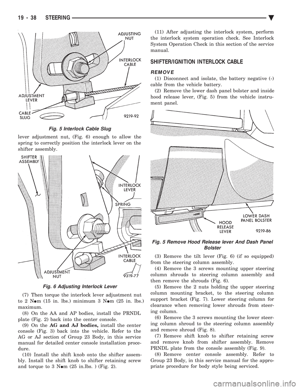
lever adjustment nut, (Fig. 6) enough to allow the
spring to correctly position the interlock lever on the
shifter assembly.
(7) Then torque the interlock lever adjustment nut
to2N Im (15 in. lbs.) minimum 3 N Im (25 in. lbs.)
maximum. (8) On the AA and AP bodies, install the PRNDL
plate (Fig. 2) back into the center console. (9) On the AG and AJ bodies, install the center
console (Fig. 3) back into the vehicle. Refer to the
AG or AJ section of Group 23 Body, in this service
manual for detailed center console installation proce-
dure. (10) Install the shift knob onto the shifter assem-
bly. Install the shift knob to shifter retaining screw
and torque to 3 N Im (25 in.lbs. ) (Fig. 2). (11) After adjusting the interlock system, perform
the interlock system operation check. See Interlock
System Operation Check in this section of the service
manual.
SHIFTER/IGNITION INTERLOCK CABLE
REMOVE
(1) Disconnect and isolate, the battery negative (-)
cable from the vehicle battery. (2) Remove the lower dash panel bolster and inside
hood release lever, (Fig. 5) from the vehicle instru-
ment panel.
(3) Remove the tilt lever (Fig. 6) (if so equipped)
from the steering column assembly. (4) Remove the 3 screws mounting upper steering
column shrouds to steering column assembly and
then remove the shrouds (Fig. 6). (5) Remove the 2 nuts holding the upper steering
column mounting bracket, to the steering column
support bracket (Fig. 7). Lower steering column for
clearance when removing lower shrouds from steer-
ing column. (6) Remove the 3 screws mounting the lower steer-
ing column shroud to the steering column assembly
and remove shroud (Fig. 8). (7) Remove shift knob to shifter retaining screw
and remove knob from shifter assembly. Remove
PRNDL plate from the console assembly (Fig. 9). (8) Remove center console assembly. Refer to
Group 23 Body, in this service manual for the appro-
priate procedure for body style being serviced.
Fig. 5 Interlock Cable Slug
Fig. 6 Adjusting Interlock Lever
Fig. 5 Remove Hood Release lever And Dash Panel Bolster
19 - 38 STEERING Ä
Page 1958 of 2438
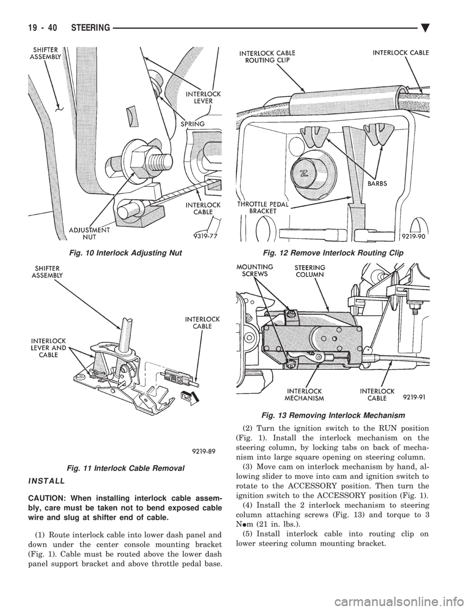
INSTALL
CAUTION: When installing interlock cable assem-
bly, care must be taken not to bend exposed cable
wire and slug at shifter end of cable.
(1) Route interlock cable into lower dash panel and
down under the center console mounting bracket
(Fig. 1). Cable must be routed above the lower dash
panel support bracket and above throttle pedal base. (2) Turn the ignition switch to the RUN position
(Fig. 1). Install the interlock mechanism on the
steering column, by locking tabs on back of mecha-
nism into large square opening on steering column. (3) Move cam on interlock mechanism by hand, al-
lowing slider to move into cam and ignition switch to
rotate to the ACCESSORY position. Then turn the
ignition switch to the ACCESSORY position (Fig. 1). (4) Install the 2 interlock mechanism to steering
column attaching screws (Fig. 13) and torque to 3
N Im (21 in. lbs.).
(5) Install interlock cable into routing clip on
lower steering column mounting bracket.
Fig. 10 Interlock Adjusting Nut
Fig. 11 Interlock Cable Removal
Fig. 12 Remove Interlock Routing Clip
Fig. 13 Removing Interlock Mechanism
19 - 40 STEERING Ä
Page 1959 of 2438
CAUTION: Interlock cable must by completely
clipped to the throttle pedal bracket with both barbs
of clip fully installed through mounting holes. This
is to prevent interference with throttle pedal.
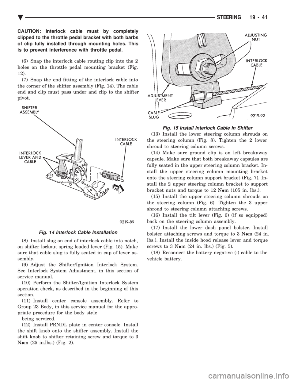
(6) Snap the interlock cable routing clip into the 2
holes on the throttle pedal mounting bracket (Fig.
12). (7) Snap the end fitting of the interlock cable into
the corner of the shifter assembly (Fig. 14). The cable
end and clip must pass under and clip to the shifter
pivot.
(8) Install slug on end of interlock cable into notch,
on shifter lockout spring loaded lever (Fig. 15). Make
sure that cable slug is fully seated in cup of lever as-
sembly. (9) Adjust the Shifter/Ignition Interlock System.
See Interlock System Adjustment, in this section of
service manual. (10) Perform the Shifter/Ignition Interlock System
operation check, as described in the beginning of this
section. (11) Install center console assembly. Refer to
Group 23 Body, in this service manual for the appro-
priate procedure for the body style being serviced.
(12) Install PRNDL plate in center console. Install
the shift knob onto the shifter assembly. Install the
shift knob to shifter retaining screw and torque to 3
N Im (25 in.lbs.) (Fig. 2). (13) Install the lower steering column shrouds on
the steering column (Fig. 8). Tighten the 2 lower
shroud to steering column screws. (14) Make sure ground clip is on left breakaway
capsule. Make sure that both breakaway capsules are
fully seated in the upper steering column bracket. In-
stall the upper steering column mounting bracket
onto the steering column support bracket (Fig. 7). In-
stall the 2 upper steering column bracket to support
bracket nuts and torque to 12 N Im (105 in. lbs.).
(15) Install the upper steering column shrouds on
the steering column (Fig. 6). Tighten the 3 upper
shroud to steering column attaching screws. (16) Install the tilt lever (Fig. 6) (if so equipped)
back on the steering column assembly. (17) Install the lower dash panel bolster. Install
bolster attaching screws and torque to 3 N Im (24 in.
lbs.). Install the inside hood release lever and torque
screws to 3 N Im (24 in. lbs.) (Fig. 5).
(18) Reconnect the battery negative (-) cable to the
vehicle battery.
Fig. 14 Interlock Cable Installation
Fig. 15 Install Interlock Cable In Shifter
Ä STEERING 19 - 41
Page 2167 of 2438
AA-VEHICLE BODY COMPONENT SERVICE INDEX
page page
A-Pillar and Roof Rail Mouldings ............. 25
B-Pillar Trim Panel ....................... 25
Body Side Moulding and Applique ............ 24
Cowl Cover ............................. 13
Cowl Panel Trim and Scuff Plates ............ 25
Door Opening Weatherstrips ................ 24
Floor Carpet ............................ 30
Front Center Console ..................... 29
Front Door and Hinge ..................... 15
Front Door Belt Moulding and Weatherstrip ..... 17
Front Door Glass ........................ 17
Front Door Glass Channel and Run Weatherstrip . 18
Front Door Glass Run Lower Channel ......... 18
Front Door Latch ......................... 16
Front Door Side View Mirror ................ 17
Front Door Silencer and Water Shield ......... 15
Front Door Trim Panel .................... 14
Front Door Window Regulator/Manual ......... 18
Front Door Window Regulator/Power .......... 19
Front End Splash Shields .................. 13
Front Fender ............................ 14
Front Power Door Lock Actuator ............. 19
Front Seat Belts ......................... 27
Front Seats ............................. 28
Fuel Fill Door ........................... 36
Grille .................................. 11
Head Lining ............................. 30
Hood and Hinges ........................ 11
Hood Latch and Release Cable .............. 12
Outside Front Door Latch Release Handle ..... 16
Outside Rear Door Latch Release Handle ...... 21 Overhead Console
........................ 30
Quarter Extension Trim Panel ............... 27
Quarter Trim Panel ....................... 27
Rear Deck Filler Panel .................... 31
Rear Door and Hinge ..................... 20
Rear Door Belt Moulding and Weatherstrip ..... 22
Rear Door Glass ......................... 22
Rear Door Glass Run Weatherstrip ........... 22
Rear Door Glass Stationary Glass Module ..... 23
Rear Door Latch ......................... 21
Rear Door Silencer and Water Shield ......... 20
Rear Door Trim Panel ..................... 20
Rear Door Window Regulator/Manual ......... 23
Rear Door Window Regulator/Power .......... 23
Rear Power Door Lock Actuator ............. 22
Rear Seat Belts .......................... 28
Rear Seats ............................. 28
Rear Shelf Trim Panel ..................... 27
Rear Window Glass ...................... 32
Sun Roof Air Deflector .................... 31
Sun Roof Drain Tubes .................... 31
Sun Roof Weatherstrip .................... 31
Trunk Lid .............................. 33
Trunk Lid Hinge ......................... 34
Trunk Lid Latch .......................... 34
Trunk Lid Lock .......................... 34
Trunk Lid Luggage Rack ................... 35
Trunk Lid Torsion Bar ..................... 34
Trunk Lining ............................ 35
Trunk Opening Weatherstrip ................ 35
Vinyl Roof Bonnet ........................ 31
GRILLE
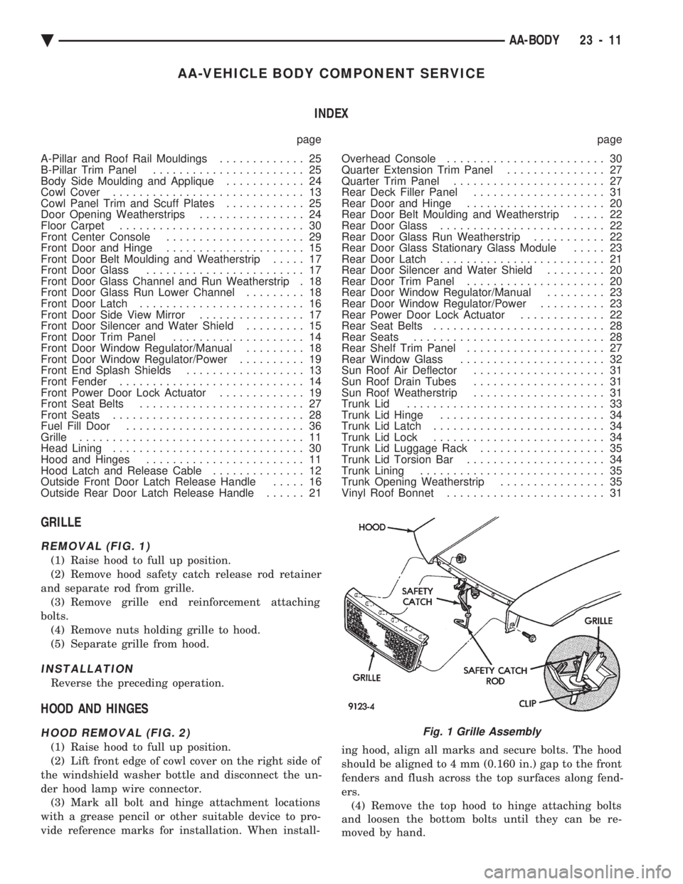
REMOVAL (FIG. 1)
(1) Raise hood to full up position.
(2) Remove hood safety catch release rod retainer
and separate rod from grille. (3) Remove grille end reinforcement attaching
bolts. (4) Remove nuts holding grille to hood.
(5) Separate grille from hood.
INSTALLATION
Reverse the preceding operation.
HOOD AND HINGES
HOOD REMOVAL (FIG. 2)
(1) Raise hood to full up position.
(2) Lift front edge of cowl cover on the right side of
the windshield washer bottle and disconnect the un-
der hood lamp wire connector. (3) Mark all bolt and hinge attachment locations
with a grease pencil or other suitable device to pro-
vide reference marks for installation. When install- ing hood, align all marks and secure bolts. The hood
should be aligned to 4 mm (0.160 in.) gap to the front
fenders and flush across the top surfaces along fend-
ers. (4) Remove the top hood to hinge attaching bolts
and loosen the bottom bolts until they can be re-
moved by hand.
Fig. 1 Grille Assembly
Ä AA-BODY 23 - 11
Page 2184 of 2438
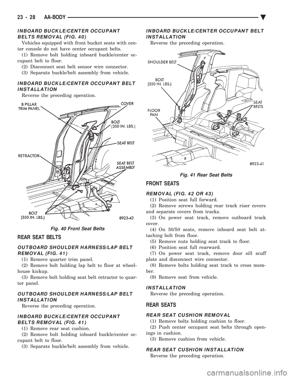
INBOARD BUCKLE/CENTER OCCUPANT BELTS REMOVAL (FIG. 40)
Vehicles equipped with front bucket seats with cen-
ter console do not have center occupant belts. (1) Remove bolt holding inboard buckle/center oc-
cupant belt to floor. (2) Disconnect seat belt sensor wire connector.
(3) Separate buckle/belt assembly from vehicle.
INBOARD BUCKLE/CENTER OCCUPANT BELT INSTALLATION
Reverse the preceding operation.
REAR SEAT BELTS
OUTBOARD SHOULDER HARNESS/LAP BELTREMOVAL (FIG. 41)
(1) Remove quarter trim panel.
(2) Remove bolt holding lap belt to floor at wheel-
house kickup. (3) Remove bolt holding seat belt retractor to quar-
ter panel.
OUTBOARD SHOULDER HARNESS/LAP BELT INSTALLATION
Reverse the preceding operation.
INBOARD BUCKLE/CENTER OCCUPANTBELTS REMOVAL (FIG. 41)
(1) Remove rear seat cushion.
(2) Remove bolt holding inboard buckle/center oc-
cupant belt to floor. (3) Separate buckle/belt assembly from vehicle.
INBOARD BUCKLE/CENTER OCCUPANT BELTINSTALLATION
Reverse the preceding operation.
FRONT SEATS
REMOVAL (FIG. 42 OR 43)
(1) Position seat full forward.
(2) Remove screws holding rear track riser covers
and separate covers from tracks. (3) On power seat track, remove outboard track
cover. (4) On 50/50 seats, remove inboard seat belt at-
taching bolt from floor. (5) Remove nuts holding seat track to floor.
(6) Position seat full rearward.
(7) On power seat track, remove door sill scuff
plate and disconnect wire connector. (8) Remove bolts holding seat track to cross mem-
ber. (9) Remove seat from vehicle.
INSTALLATION
Reverse the preceding operation.
REAR SEATS
REAR SEAT CUSHION REMOVAL
(1) Remove bolts holding cushion to floor.
(2) Push center occupant seat belts through open-
ings in cushion. (3) Remove cushion from vehicle.
REAR SEAT CUSHION INSTALLATION
Reverse the preceding operation.
Fig. 40 Front Seat Belts
Fig. 41 Rear Seat Belts
23 - 28 AA-BODY Ä
Page 2185 of 2438
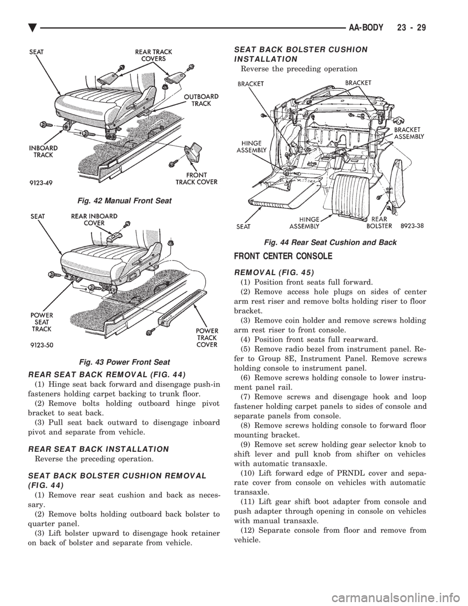
REAR SEAT BACK REMOVAL (FIG. 44)
(1) Hinge seat back forward and disengage push-in
fasteners holding carpet backing to trunk floor. (2) Remove bolts holding outboard hinge pivot
bracket to seat back. (3) Pull seat back outward to disengage inboard
pivot and separate from vehicle.
REAR SEAT BACK INSTALLATION
Reverse the preceding operation.
SEAT BACK BOLSTER CUSHION REMOVAL (FIG. 44)
(1) Remove rear seat cushion and back as neces-
sary. (2) Remove bolts holding outboard back bolster to
quarter panel. (3) Lift bolster upward to disengage hook retainer
on back of bolster and separate from vehicle.
SEAT BACK BOLSTER CUSHION INSTALLATION
Reverse the preceding operation
FRONT CENTER CONSOLE
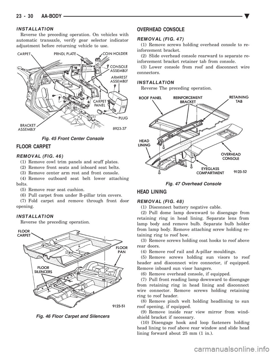
REMOVAL (FIG. 45)
(1) Position front seats full forward.
(2) Remove access hole plugs on sides of center
arm rest riser and remove bolts holding riser to floor
bracket. (3) Remove coin holder and remove screws holding
arm rest riser to front console. (4) Position front seats full rearward.
(5) Remove radio bezel from instrument panel. Re-
fer to Group 8E, Instrument Panel. Remove screws
holding console to instrument panel. (6) Remove screws holding console to lower instru-
ment panel rail. (7) Remove screws and disengage hook and loop
fastener holding carpet panels to sides of console and
separate panels from console. (8) Remove screws holding console to forward floor
mounting bracket. (9) Remove set screw holding gear selector knob to
shift lever and pull knob from shifter on vehicles
with automatic transaxle. (10) Lift forward edge of PRNDL cover and sepa-
rate cover from console on vehicles with automatic
transaxle. (11) Lift gear shift boot adapter from console and
push adapter through opening in console on vehicles
with manual transaxle. (12) Separate console from floor and remove from
vehicle.
Fig. 42 Manual Front Seat
Fig. 43 Power Front Seat
Fig. 44 Rear Seat Cushion and Back
Ä AA-BODY 23 - 29
Page 2186 of 2438
INSTALLATION
Reverse the preceding operation. On vehicles with
automatic transaxle, verify gear selector indicator
adjustment before returning vehicle to use.
FLOOR CARPET
REMOVAL (FIG. 46)
(1) Remove cowl trim panels and scuff plates.
(2) Remove front seats and inboard seat belts.
(3) Remove center arm rest and front console.
(4) Remove outboard seat belt lower attaching
bolts. (5) Remove rear seat cushion.
(6) Pull carpet from under B-pillar trim covers.
(7) Fold carpet and remove through front door
opening.
INSTALLATION
Reverse the preceding operation.
OVERHEAD CONSOLE
REMOVAL (FIG. 47)
(1) Remove screws holding overhead console to re-
inforcement bracket. (2) Slide overhead console rearward to separate re-
inforcement bracket retainer tab from console. (3) Lower console from roof and disconnect wire
connectors.
INSTALLATION
Reverse The preceding operation.
HEAD LINING
REMOVAL (FIG. 48)
(1) Disconnect battery negative cable.
(2) Pull dome lamp downward to disengage from
retaining ring in head lining. Separate lens from
lamp body and remove bulb. Separate bulb holder
from lamp body. Remove attaching screw holding re-
taining ring to roof bow. (3) Remove screws holding coat hooks to roof above
rear doors. (4) Remove roof rail and A-pillar mouldings.
(5) Remove screws holding sun visors to roof
header and disconnect wire connector, if equipped.
Remove inboard sun visor hangers. (6) Remove overhead console, if equipped.
(7) Pull front reading lamp downward to disengage
from retaining ring in head lining and disconnect
wire connector. Remove screws holding retaining
ring to roof header. (8) Remove pinch welt holding headlining to sun
roof opening, if equipped. (9) Remove inside rear view mirror from wind-
shield bracket if necessary. (10) Disengage hook and loop fasteners holding
head lining to roof above rear window and slide head
lining forward about 25 mm (1 in.).
Fig. 45 Front Center Console
Fig. 46 Floor Carpet and Silencers
Fig. 47 Overhead Console
23 - 30 AA-BODY Ä