cruise control CHEVROLET DYNASTY 1993 Service Manual
[x] Cancel search | Manufacturer: CHEVROLET, Model Year: 1993, Model line: DYNASTY, Model: CHEVROLET DYNASTY 1993Pages: 2438, PDF Size: 74.98 MB
Page 719 of 2438
ity 9 and pin 7 of the control module 25-way connec-
tor. The vehicle speed sensor signal can be tested
with a volt/ohmmeter at pin 7 of the control module
25-way connector. Turn on the vehicle ignition and
check fo r a 5 volt signal as the vehicle is moved
about 3 to 5 feet. If not repair open wiring, terminal
push out, bad crimp, drive in vehicle speed sensor,
etc., as necessary to correct condition. Ensure that
the 25-way connector is plugged into the control
module securely. Road test vehicle after repairs have
been made to ensure that no recalls can occur while
moving.
CONDITION: INSTRUMENT CLUSTER SPEEDOMETER STAYS AT 0 MPH/ (0 KM/H)WHILE VEHICLE IS MOVING, BODYCOMPUTER DOES NOT LOCK DOORS AT 15MPH (24 KM/H), AND THE SPEED CONTROLWILL NOT ACCEPT A SPEED SET.
PROCEDURE
(1) Remove driver's seat anchor bolts and nuts. Ad-
just the driver's seat to a safe driving position. Dis-
connect the 25-way connector from the memory seat
control module. Replace the driver's seat anchor bolts
and nuts. Road test the vehicle to complete this diag-
nosis. If the doors lock, the cruise control accepts a
set, and the speedometer now works, replace the
Memory Seat control module. (2) After replacing the Memory Seat control mod-
ule, perform the memory seat diagnostic self tests.
This teaches the new module it's soft limits and now
re-road test the vehicle before returning it to the cus-
tomer.
CONDITION: NO SEAT MOVEMENT IN THE RECALL MODE, SEAT WILL MOVE BYMANUAL SWITCH ACTUATION IN ALLDIRECTIONS WITHOUT STALL DETECTION.
PROCEDURE
(1) Check for 5 volts at pin 10 of the control mod-
ule 25-way connector. This is the 5 volt feed from the
control module to the seat track position sensing po-
tentiometer. (2) Check for ground at pin 8 of the control module
25-way connector. To test for ground, one lead of the
voltmeter must be connected to either the 5 volt sup-
ply for the control module or the battery positive. If
the sense voltage and ground are NOT present at the
above pins of the 21-way control module connector.
When the seat switch is pressed, replace the control
module. An inadvertent application of battery volt-
age to the circuit could damaged the control module.
If the voltage and ground circuits are present then
continue this procedure. (3) Check for 5 volts at pin 5 of the natural 5-way
connector plugged into the power seat adjuster mo-
tors end-bell. (4) Check for ground at pin 4 of the natural 5-way
connector plugged into the power seat adjuster mo-
tors end-bell. If the power seat adjuster still has no
movement in the recall mode, then continue this pro-
cedure. (5) Disconnect the natural 5-way connector from
the power seat adjuster motors end-bell. (6) Check with an ohmmeter for a resistance read-
ing that may be from 2600 to 4000 ohms between
pins 4 and 5 of the motors end-bell connector. If
there is an open circuit reading or the reading ob-
tained falls outside this range, then replace the seat
motor package assembly. After replacement of the
seat motor package, reconnect all wiring connectors
and reinstall seat assembly in vehicle. Operate the
switches manually to cause maximum seat move-
ment in all directions. Perform the memory seat di-
agnostic self check so the control module will learn
the new soft limits of the assembly.
CONDITION: NO SEAT TRACK FORWARD OR REARWARD MOVEMENT IN THE RECALLMODE, SEAT TRACK WILL MOVE FORWARDOR REARWARD BY MANUAL SWITCHACTUATION WITHOUT STALL DETECTION.
PROCEDURE
(1) Check for a voltage at pin 12 of the control
module 21-way connector. Less than 5 volts for the
seat track fully forward and more than 0 volts when
fully rearward. This voltage should vary correspond-
ing to the position. (2) Check for a voltage at pin 1 of the natural
5-way connector, Same as in step (1) above. The
ground lead connected to pin 4 of the 5-way connec-
tor. If the voltage reading is at 0 volts, disconnect
the 5-way natural connector and check for a short to
ground in the harness. If no short is found, reconnect
the connector and continue the procedure. (3) Check for the voltage to vary as noted above, if
it does not vary as the seat track is moved forward
and rearward, the sensing potentiometer is defective.
Replace the seat motor package assembly. After re-
placement of the seat motor package, reconnect all
wiring connectors and reinstall seat assembly in ve-
hicle. Operate the switches manually to cause maxi-
mum seat movement in all directions. Perform the
memory seat diagnostic self check so the control
module will learn the new soft limits of the assem-
bly.
Ä POWER SEATS 8R - 13
Page 1772 of 2438
TACHOMETERÐPCM OUTPUT
The PCM supplies engine RPM to the instrument
panel tachometer. Refer to Group 8 for tachometer
information.
MODES OF OPERATION
As input signals to the PCM change, the PCM
adjusts its response to the output devices. For example,
the PCM must calculate a different injector pulse
width and ignition timing for idle than it does for wide
open throttle (WOT). There are several different modes
of operation that determine how the PCM responds to
the various input signals. There are two different areas of operation, OPEN
LOOP and CLOSED LOOP. During OPEN LOOP modes, the PCM receives input
signals and responds according to preset PCM pro-
gramming. Input from the oxygen (O
2) sensor is not
monitored during OPEN LOOP modes. During CLOSED LOOP modes, the PCM does moni-
tor the oxygen (O
2) sensor input. This input tells the
PCM if the calculated injector pulse width results in an
air-fuel ratio of 14.7 to 1. By monitoring the exhaust
oxygen content, the can PCM fine tune injector pulse
width for optimum fuel economy and low emissions. The single point fuel injection system has the follow-
ing modes of operation:
² Ignition switch ON - Zero RPM
² Engine start-up
² Engine warm-up
² Cruise (Idle)
² Acceleration
² Deceleration
² Wide Open Throttle
² Ignition switch OFF
The engine start-up (cranking), engine warm-up, and
wide open throttle modes are OPEN LOOP modes. The
acceleration, deceleration, and cruise modes, with the
engine at operating temperature are CLOSED
LOOP modes (under most operating conditions).
IGNITION SWITCH ON (ZERO RPM) MODE
When the single point fuel injection system is acti-
vated by the ignition switch, the following actions
occur:
² The PCM determines atmospheric air pressure from
the MAP sensor input to calculate basic fuel strategy.
² The PCM monitors the coolant temperature sensor
and throttle position sensor inputs. The PCM modifies
fuel strategy based on these inputs. When the key is in the ON position and the engine is
not running, the (ASD) and fuel pump relays are not
energized. Therefore, battery voltage is not supplied to
the fuel pump, ignition coil, fuel injector or oxygen
sensor heating element. ENGINE START-UP MODE
This is an OPEN LOOP mode. The following actions
occur when the starter motor is engaged. If the PCM receives a distributor signal it energizes
the auto shutdown (ASD) relay and fuel pump relay to
supply battery voltage to the fuel injector, ignition coil
and oxygen sensor heating element. If the PCM does
not receive a distributor input, it de-energizes the ASD
and fuel pump relays after approximately one second. When the engine idles within 664 RPM of the target
RPM, the PCM compares the current MAP value with
the atmospheric pressure value it received during the
Ignition Switch On (Zero RPM) Mode. If a minimum
difference between the two is not detected, a MAP
sensor fault is set into memory. Once the ASD relay and fuel pump relay have ener-
gized, the PCM:
² Supplies a ground path to the injector. The injector
is pulsed four times per engine revolution instead of
the normal two pulses per revolution.
² Determines injector pulse width based on coolant
temperature, MAP sensor input, throttle position, and
the number of engine revolutions since cranking was
initiated.
² Monitors the coolant temperature sensor, distribu-
tor pick-up, MAP sensor, and throttle position sensor to
determine correct ignition timing.
ENGINE WARM-UP MODE
This is a OPEN LOOP mode. The following inputs
are received by the PCM:
² coolant temperature
² manifold absolute pressure (MAP)
² engine speed (distributor pick-up)
² throttle position
² A/C switch
² battery voltage
The PCM provides a ground path for the injector to
precisely control injector pulse width (by switching the
ground on and off) and fires the injector twice per
engine revolution. The PCM regulates ignition timing.
It also adjusts engine idle speed through the idle air
control motor.
CRUISE OR IDLE MODE
When the engine is at operating temperature this is
a CLOSED LOOP mode. During cruising speed and at
idle the following inputs are received by the PCM:
² coolant temperature
² manifold absolute pressure
² engine speed
² throttle position
² exhaust gas oxygen content
² A/C control positions
² battery voltage
14 - 32 FUEL SYSTEMS Ä
Page 1803 of 2438
mode, the PCM compensates for the failure of certain
components that send incorrect signals. The PCM
substitutes for the incorrect signals with inputs from
other sensors and by using stored default values.Signals that can trigger the Malfunction Indi-
cator (Check Engine) Lamp.
² An emission system component
² Battery Voltage Input
² Charging system
² Engine Coolant Temperature Sensor
² Manifold Absolute Pressure Sensor
² Methanol Concentration Sensor
² Throttle Position Sensor
The malfunction indicator lamp can also display
diagnostic trouble codes. Cycle the ignition switch on,
off, on, off, on, within five seconds and the PCM
displays any diagnostic trouble codes stored in
memory. Refer to the 2.5L Flexible Fuel Multi-Port
Fuel InjectionÐOn Board Diagnostics section in this
group for diagnostic trouble code descriptions.
RADIATOR FAN RELAYÐPCM OUTPUT
The radiator fan is energized by the PCM through
the radiator fan relay. The PCM grounds the radiator
fan relay when engine coolant reaches a predetermined
temperature. For more information, refer to Group 7,
Cooling Systems. The radiator fan relay is mounted on the drivers side
fender well, next to the strut tower (Fig. 11).
SPEED CONTROL SOLENOIDSÐPCM OUTPUT
The speed control vacuum and vent solenoids are
operated by the PCM. When the PCM supplies a
ground to the vacuum and vent solenoids, the speed
control system opens the throttle blade. When the PCM
supplies a ground only to the vent solenoid, the throttle
blade holds position. When the PCM removes the
ground from both the vacuum and vent solenoids, the
throttle blade closes. The PCM balances the two sole-
noids to maintain the set speed. Refer to Group 8H for
speed control information.
TACHOMETERÐPCM OUTPUT
The PCM supplies engine RPM to the instrument
panel tachometer. Refer to Group 8 for tachometer
information.
TORQUE CONVERTER CLUTCH SOLENOIDÐPCM
OUTPUT
Three-speed automatic transaxles use a torque con-
verter clutch solenoid. The PCM controls the lock-up of
the torque convertor through the solenoid. The tran-
saxle is locked up only in direct drive mode. Refer to
Group 21 for transaxle information.
MODES OF OPERATION
As input signals to the PCM change, the PCM
adjusts its response to the output devices. For example, the PCM must calculate a different injector pulse
width and ignition timing for idle than it does for wide
open throttle (WOT). There are several different modes
of operation that determine how the PCM responds to
the various input signals. There are two different areas of operation, Open
Loop and Closed Loop. During Open Loop modes, the PCM receives input
signals and responds according to preset PCM pro-
gramming. Input from the oxygen (O
2) sensor is not
monitored during Open Loop modes. During CLOSED LOOP modes, the PCM does moni-
tor the oxygen (O
2) sensor input. The input indicates if
the calculated injector pulse width results in the ideal
air-fuel ratio for the current percentage of methanol in
the fuel. By monitoring the exhaust oxygen content
through the O
2sensor, the PCM can fine tune the
injector pulse width to achieve optimum fuel economy
combined with low emissions. The 2.5L flexible fuel multi-port fuel injection system
has the following modes of operation:
² Ignition switch ON - Zero RPM
² Engine start-up
² Engine warm-up
² Cruise (Idle)
² Acceleration
² Deceleration
² Wide Open Throttle
² Ignition switch OFF
The engine start-up (crank), engine warm-up, and
wide open throttle modes are OPEN LOOP modes. The
acceleration, deceleration, and cruise modes, with the
engine at operating temperature are CLOSED
LOOP modes (under most operating conditions).
IGNITION SWITCH ON (ZERO RPM) MODE
When the ignition switch cycles and past the On
position, the fuel injection system activates and the
following actions occur:
² For two seconds at key ON (and during cranking),
the methanol concentration sensor calibrates the PCM.
During the calibration period the sensor sends 4.45
volts to the PCM as a correction factor. After the
calibration period, the methanol concentration sensor
output represents the methanol percentage in the fuel.
² The PCM calculates basic fuel strategy by determin-
ing atmospheric air pressure from the MAP sensor
input.
² The PCM monitors the coolant temperature sensor
and throttle position sensor input. The PCM modifies
fuel strategy based on this input. When the key is in the ON position and the engine is
not running, the auto shutdown (ASD) relay and fuel
pump relay are not energized. Therefore battery volt-
age is not supplied to the fuel pump, ignition coil, fuel
injector or oxygen sensor heating element.
Ä FUEL SYSTEMS 14 - 63
Page 1804 of 2438
ENGINE START-UP MODE
This is an OPEN LOOP mode. The following ac-
tions occur when the starter motor is engaged. The methanol concentration sensor finishes cali-
brating the PCM (takes approximately two seconds).
After the calibration period, the PCM determines the
methanol content of the fuel from the methanol con-
centration sensor input. If the PCM receives a camshaft position sensor
(distributor pick-up) signal it energizes the auto
shutdown (ASD) relay and fuel pump relay. These re-
lays supply battery voltage to the fuel injector, igni-
tion coil and oxygen sensor heating element. If the
PCM does not receive a camshaft position sensor sig-
nal, it de-energizes the ASD and fuel pump relays af-
ter approximately one second. With the engine idling within 664 RPM of the tar-
get RPM, the PCM compares the current MAP value
with the atmospheric pressure value it received dur-
ing the Ignition Switch On (Zero RPM) Mode. If a
minimum difference between the two is not detected,
a MAP sensor fault is set into memory. Once the ASD relay and fuel pump relay have en-
ergized, the PCM:
² Supplies a ground path to each injector. The injec-
tors are pulsed four times per engine revolution in-
stead of the normal two pulses per revolution.
² Determines injector pulse width based on engine
coolant temperature, methanol concentration sensor
input, MAP sensor input, throttle position, and the
number of engine revolutions since cranking was ini-
tiated.
² Monitors the coolant temperature sensor, camshaft
position sensor, MAP sensor, methanol concentration
sensor, and throttle position sensor to determine cor-
rect ignition timing.
ENGINE WARM-UP MODE
This is a OPEN LOOP mode. The following inputs
are received by the PCM:
² Engine coolant temperature
² Engine speed
² Manifold absolute pressure (MAP)
² Methanol percentage in fuel
² Throttle position
² A/C switch
² Battery voltage
The PCM determines the methanol content of the
fuel from the methanol concentration sensor input. The PCM provides a ground path for the injectors
and energizes them in sequence. The PCM precisely
controls injector pulse width by switching the ground
on and off. The PCM regulates engine idle speed by adjusting
the idle air control motor. Also, the PCM adjusts ig-
nition timing.
CRUISE OR IDLE MODE
When the engine is at operating temperature, this
is a CLOSED LOOP mode. During cruising speed the
following inputs are received by the PCM:
² Engine coolant temperature
² Manifold absolute pressure
² Methanol percentage in fuel
² Engine speed
² Throttle position
² Exhaust gas oxygen content
² A/C control positions
² Battery voltage
The PCM determines the methanol content of the
fuel from the methanol concentration sensor input. The PCM provides a ground path for the injectors
to precisely control injector pulse width. The PCM
controls engine idle speed and ignition timing. The
PCM controls the air/fuel ratio according to the oxy-
gen content in the exhaust gas.
ACCELERATION MODE
This is a CLOSED LOOP mode. The PCM recog-
nizes an abrupt increase in throttle position or MAP
pressure as a demand for increased engine output
and vehicle acceleration. The PCM increases injector
pulse width in response to increased fuel demand.
DECELERATION MODE
This is a CLOSED LOOP mode. During decelera-
tion the following inputs are received by the PCM:
² Engine coolant temperature
² Manifold absolute pressure
² Methanol percentage in fuel
² Engine speed
² Throttle position
² Exhaust gas oxygen content
² A/C control positions
² Battery voltage
The PCM may receive a closed throttle input from
the TPS at the same time it senses an abrupt de-
crease in manifold absolute pressure. This indicates a
hard deceleration. In response, the PCM may modify
the injector firing sequence. Modifying the injector
firing sequence helps maintain better control of the
air-fuel mixture (as sensed through the O
2sensor).
WIDE OPEN THROTTLE MODE
This is an OPEN LOOP mode. During wide open
throttle operation, the following inputs are received
by the PCM:
² Engine coolant temperature
² Manifold absolute pressure
² Methanol percentage in fuel
² Engine speed
² Throttle position
When the PCM senses a wide open throttle condi-
tion, it de-energizes the air conditioning clutch relay.
This disables the air conditioning system.
14 - 64 FUEL SYSTEMS Ä
Page 1832 of 2438
noid is energized. The solenoid mounts to the passen-
ger side inner fender panel, next to the strut tower
(Fig. 17).
MODES OF OPERATION
As input signals to the PCM change, the PCM
adjusts its response to the output devices. For example,
the PCM must calculate a different injector pulse
width and ignition timing for idle than it does for wide
open throttle (WOT). There are several different modes
of operation that determine how the PCM responds to
the various input signals. There are two different areas of operation, OPEN
LOOP and CLOSED LOOP. During OPEN LOOP modes, the PCM receives input
signals and responds according to preset PCM pro-
gramming. Input from the oxygen (O
2) sensor is not
monitored during OPEN LOOP modes. During CLOSED LOOP modes, the PCM does moni-
tor the oxygen (O
2) sensor input. This input indicates
to the PCM whether or not the calculated injector pulse
width results in the ideal air-fuel ratio of 14.7 parts air
to 1 part fuel. By monitoring the exhaust oxygen
content through the O
2sensor, the PCM can fine tune
the injector pulse width to achieve optimum fuel
economy combined with low emissions. The 2.2L Turbo III multi-port fuel injection system
has the following modes of operation:
² Ignition switch ON - Zero RPM
² Engine start-up
² Engine warm-up
² Cruise (Idle)
² Acceleration
² Deceleration
² Wide Open Throttle
² Ignition switch OFF
The engine start-up (crank), engine warm-up, and
wide open throttle modes are OPEN LOOP modes. The
acceleration, deceleration, and cruise modes, with the
engine at operating temperature are CLOSED
LOOP modes (under most operating conditions).
IGNITION SWITCH ON (ZERO RPM) MODE
When the ignition switch activates the fuel injection
system the following actions occur:
²
The PCM calculates basic fuel strategy by determining
atmospheric air pressure from the MAP sensor input.
² The PCM monitors the coolant temperature sensor
and throttle position sensor input. The PCM modifies
fuel strategy based on this input. When the key is in the ON position and the engine is
not running, the auto shutdown (ASD) relay and fuel
pump relay are not energized. Therefore battery volt-
age is not supplied to the fuel pump, ignition coil, fuel
injector or oxygen sensor heating element.
ENGINE START-UP MODE
This is an OPEN LOOP mode. The following actions
occur when the starter motor is engaged. If the PCM receives the camshaft position and crank-
shaft position sensor signals, it energizes the auto
shutdown (ASD) relay and fuel pump relay. These
relays supply battery voltage to the fuel pump, fuel
injectors, ignition coil, and oxygen sensor heating ele-
ment. If the PCM does not receive the camshaft posi-
tion sensor and crankshaft position sensor signals
within approximately one second, it de-energizes the
ASD relay and fuel pump relay. The PCM energizes all injectors until it determines
crankshaft position from the camshaft position sensor
and crankshaft position sensor signals. The PCM de-
termines crankshaft position within 1 engine revolu-
tion. After determining crankshaft position, the PCM be-
gins energizing the injectors in sequence. The PCM
adjusts injector pulse width and controls injector syn-
chronization by turning the individual ground paths to
the injectors On and Off. When the engine idles within 664 RPM of its target
RPM, the PCM compares current MAP sensor value
with the atmospheric pressure value received during
the Ignition Switch On (zero RPM) mode. If the PCM
does not detect a minimum difference between the two
values, it sets a MAP fault into memory. Once the ASD and fuel pump relays have been
energized, the PCM:
² Determines injector pulse width based on coolant
temperature, manifold absolute pressure (MAP) and
the number of engine revolutions since cranking was
initiated.
² Monitors the coolant temperature sensor, camshaft
position sensor, crankshaft position sensor, MAP sen-
sor, and throttle position sensor to determine correct
ignition timing.
ENGINE WARM-UP MODE
This is a OPEN LOOP mode. The following inputs
are received by the PCM:
² engine coolant temperature
² knock sensor
² manifold absolute pressure (MAP)
² engine speed (crankshaft position sensor)
² throttle position
² A/C switch
² battery voltage
The PCM provides a ground path for the injectors to
precisely control injector pulse width (by switching the
ground on and off). The PCM adjusts engine idle speed
through the idle air control motor. Also, the PCM
regulates ignition timing.
14 - 92 FUEL SYSTEMS Ä
Page 1833 of 2438
CRUISE OR IDLE MODE
When the engine is at operating temperature, this is
a CLOSED LOOP mode. During cruising speed the
following inputs are received by the PCM:
² engine coolant temperature
² knock sensor
² manifold absolute pressure
² engine speed (crankshaft position sensor)
² throttle position
² exhaust gas oxygen content
² A/C control positions
² battery voltage
The PCM provides a ground path for the injectors to
precisely control injector pulse width. The PCM adjusts
engine idle speed and ignition timing. The PCM con-
trols the air/fuel ratio according to the oxygen content
in the exhaust gas.
ACCELERATION MODE
This is a CLOSED LOOP mode. The PCM recognizes
an abrupt increase in throttle position or MAP pres-
sure as a demand for increased engine output and
vehicle acceleration. The PCM increases injector pulse
width in response to increased fuel demand.
DECELERATION MODE
This is a CLOSED LOOP mode. During deceleration
the following inputs are received by the PCM:
² engine coolant temperature
² knock sensor
² manifold absolute pressure
² engine speed (crankshaft position sensor)
² throttle position
² exhaust gas oxygen content ²
A/C control positions
² battery voltage
The PCM may receive a closed throttle input from
the throttle position sensor (TPS) at the same time it
senses an abrupt decrease in manifold pressure. This
indicates a hard deceleration. The PCM modifies the
injector sequence. This helps maintain better control
of the air-fuel mixture.
WIDE OPEN THROTTLE MODE
This is an OPEN LOOP mode. During wide-open-
throttle operation, the following inputs are received
by the PCM:
² engine coolant temperature
² knock sensor
² manifold absolute pressure
² engine speed (crankshaft position sensor)
² throttle position
When the PCM senses a wide open throttle condi-
tion it will de-energize the air conditioning relay.
This disables the air conditioning system. The exhaust gas oxygen content input is not ac-
cepted by the PCM during wide open throttle opera-
tion. The PCM will enrichen the air/fuel ratio to
increase performance and compensate for increased
combustion chamber temperature.
IGNITION SWITCH OFF MODE
This is an OPEN LOOP mode. When the ignition
switch is turned to the OFF position, the following
occurs:
² All outputs are turned off.
² No inputs are monitored.
² The PCM shuts down.
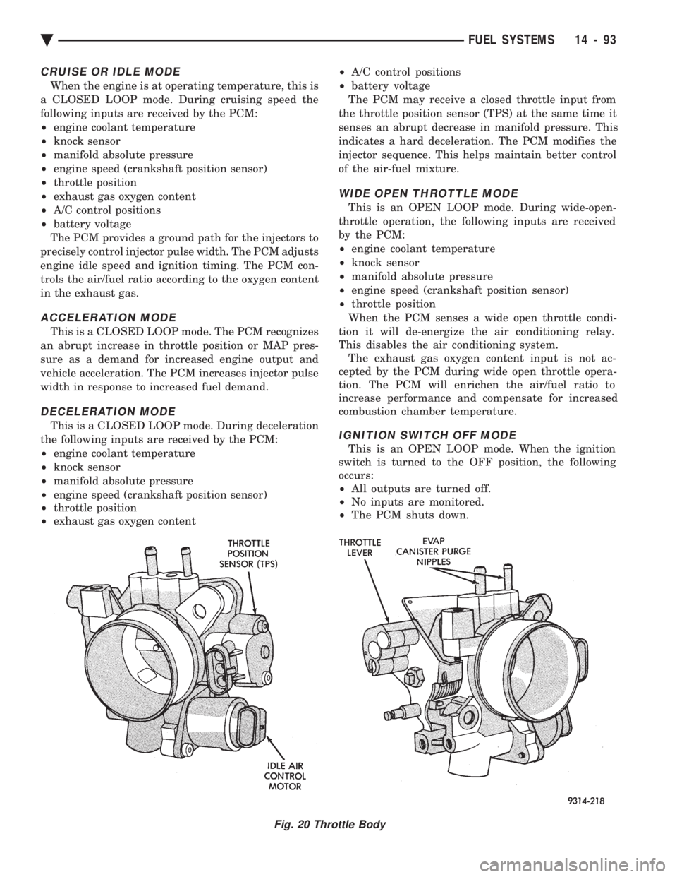
Fig. 20 Throttle Body
Ä FUEL SYSTEMS 14 - 93
Page 1861 of 2438
tially energizes all injectors at the same time. Once
the PCM determines crankshaft position, it begins
energizing the injectors in sequence.Battery voltage is supplied to the injectors through
the ASD relay. The PCM provides the ground path
for the injectors. By switching the ground path on
and off, the PCM adjusts injector pulse width. Pulse
width is the amount of time the injector is energized.
The PCM adjusts injector pulse width based on in-
puts it receives.
IGNITION COILÐPCM OUTPUT
The auto shutdown (ASD) relay provides battery
voltage to the ignition coil. The PCM provides a
ground contact (circuit) for energizing coil. When the
PCM breaks the contact, the energy in the coil pri-
mary transfers to the secondary causing the spark.
The PCM will de-energize the ASD relay if it does
not receive an input from the distributor pick-up. Re-
fer to Auto Shutdown (ASD) Relay/Fuel Pump Re-
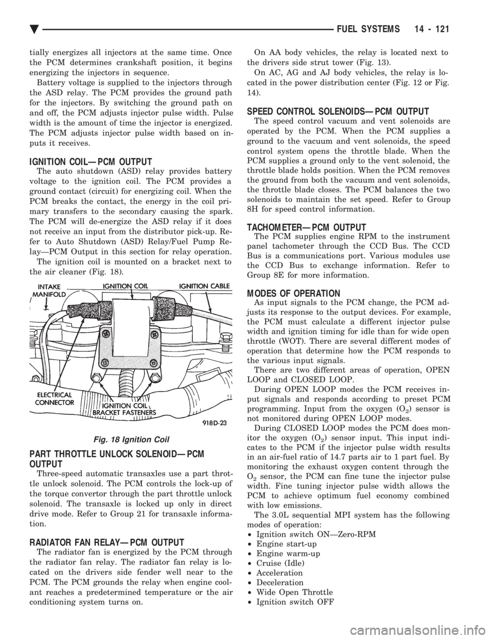
layÐPCM Output in this section for relay operation. The ignition coil is mounted on a bracket next to
the air cleaner (Fig. 18).
PART THROTTLE UNLOCK SOLENOIDÐPCM
OUTPUT
Three-speed automatic transaxles use a part throt-
tle unlock solenoid. The PCM controls the lock-up of
the torque convertor through the part throttle unlock
solenoid. The transaxle is locked up only in direct
drive mode. Refer to Group 21 for transaxle informa-
tion.
RADIATOR FAN RELAYÐPCM OUTPUT
The radiator fan is energized by the PCM through
the radiator fan relay. The radiator fan relay is lo-
cated on the drivers side fender well near to the
PCM. The PCM grounds the relay when engine cool-
ant reaches a predetermined temperature or the air
conditioning system turns on. On AA body vehicles, the relay is located next to
the drivers side strut tower (Fig. 13). On AC, AG and AJ body vehicles, the relay is lo-
cated in the power distribution center (Fig. 12 or Fig.
14).
SPEED CONTROL SOLENOIDSÐPCM OUTPUT
The speed control vacuum and vent solenoids are
operated by the PCM. When the PCM supplies a
ground to the vacuum and vent solenoids, the speed
control system opens the throttle blade. When the
PCM supplies a ground only to the vent solenoid, the
throttle blade holds position. When the PCM removes
the ground from both the vacuum and vent solenoids,
the throttle blade closes. The PCM balances the two
solenoids to maintain the set speed. Refer to Group
8H for speed control information.
TACHOMETERÐPCM OUTPUT
The PCM supplies engine RPM to the instrument
panel tachometer through the CCD Bus. The CCD
Bus is a communications port. Various modules use
the CCD Bus to exchange information. Refer to
Group 8E for more information.
MODES OF OPERATION
As input signals to the PCM change, the PCM ad-
justs its response to the output devices. For example,
the PCM must calculate a different injector pulse
width and ignition timing for idle than for wide open
throttle (WOT). There are several different modes of
operation that determine how the PCM responds to
the various input signals. There are two different areas of operation, OPEN
LOOP and CLOSED LOOP. During OPEN LOOP modes the PCM receives in-
put signals and responds according to preset PCM
programming. Input from the oxygen (O
2) sensor is
not monitored during OPEN LOOP modes. During CLOSED LOOP modes the PCM does mon-
itor the oxygen (O
2) sensor input. This input indi-
cates to the PCM if the injector pulse width results
in an air-fuel ratio of 14.7 parts air to 1 part fuel. By
monitoring the exhaust oxygen content through the
O
2sensor, the PCM can fine tune the injector pulse
width. Fine tuning injector pulse width allows the
PCM to achieve optimum fuel economy combined
with low emissions. The 3.0L sequential MPI system has the following
modes of operation:
² Ignition switch ONÐZero-RPM
² Engine start-up
² Engine warm-up
² Cruise (Idle)
² Acceleration
² Deceleration
² Wide Open Throttle
² Ignition switch OFF
Fig. 18 Ignition Coil
Ä FUEL SYSTEMS 14 - 121
Page 1862 of 2438
The engine start-up (crank), engine warm-up, and
wide open throttle modes are OPEN LOOP modes. The
acceleration, deceleration, and cruise modes, with the
engine at operating temperature are CLOSED
LOOP modes (under most operating conditions).
IGNITION SWITCH ON (ZERO RPM) MODE
When the multi-port fuel injection system is acti-
vated by the ignition switch, the following actions
occur:
² The PCM determines atmospheric air pressure from
the MAP sensor input to determine basic fuel strategy.
² The PCM monitors the coolant temperature sensor
and throttle position sensor input. The PCM modifies
fuel strategy based on these inputs. When the key is in the ON position and the engine is
not running (zero rpm), the auto shutdown (ASD) relay
and fuel pump relay are not energized. Therefore
battery voltage is not supplied to the fuel pump,
ignition coil, fuel injectors or oxygen sensor heating
element.
ENGINE START-UP MODE
This is an OPEN LOOP mode. The following actions
occur when the starter motor is engaged. If the PCM receives a distributor signal, it energizes
the auto shutdown (ASD) relay and fuel pump relay.
These relays supply battery voltage to the fuel pump,
fuel injectors, ignition coil, and oxygen sensor heating
element. If the PCM does not receive a distributor
input, the ASD relay and fuel pump relay will be
de-energized after approximately one second. The PCM energizes all six injectors until it deter-
mines crankshaft position from the distributor pick-up
signals. The PCM determines crankshaft position
within 2 engine revolutions. After determining crankshaft position, the PCM be-
gins energizing the injectors in sequence. The PCM
adjusts injector pulse width and controls injector syn-
chronization by turning the individual ground paths to
the injectors On and Off. When the engine idles within 664 RPM of its target
RPM, the PCM compares current MAP sensor value
with the atmospheric pressure value received during
the Ignition Switch On (zero RPM) mode. If the PCM
does not detect a minimum difference between the two
values, it sets a MAP fault into memory. Once the ASD and fuel pump relays have been
energized, the PCM:
² determines injector pulse width based on coolant
temperature, manifold absolute pressure (MAP) and
the number of engine revolutions since cranking was
initiated. ²
monitors the coolant temperature sensor, distribu-
tor pick-up, MAP sensor, and throttle position sensor
to determine correct ignition timing.
ENGINE WARM-UP MODE
This is a OPEN LOOP mode. The following inputs
are received by the PCM:
² engine coolant temperature
² crankshaft position (distributor pick-up)
² manifold absolute pressure (MAP)
² engine speed (distributor pick-up)
² throttle position
² A/C switch
² battery voltage
The PCM adjusts injector pulse width and controls
injector synchronization by turning the individual
ground paths to the injectors On and Off. The PCM adjusts engine idle speed by regulating
the idle air control motor and ignition timing.
CRUISE OR IDLE MODE
When the engine is at operating temperature this
is a CLOSED LOOP mode. During cruising speed the
following inputs are received by the PCM:
² engine coolant temperature
² crankshaft position (distributor pick-up)
² manifold absolute pressure
² engine speed (distributor pick-up)
² throttle position
² exhaust gas oxygen content
² A/C control positions
² battery voltage
The PCM adjusts injector pulse width and controls
injector synchronization by turning the individual
ground paths to the injectors On and Off. The PCM adjusts engine idle speed and ignition
timing. The PCM controls the air/fuel ratio according
to the oxygen content in the exhaust gas.
ACCELERATION MODE This is a CLOSED LOOP mode. The PCM recog-
nizes an abrupt increase in throttle position or MAP
pressure as a demand for increased engine output
and vehicle acceleration. The PCM increases injector
pulse width in response to increased fuel demand.
DECELERATION MODE This is a CLOSED LOOP mode. During decelera-
tion the following inputs are received by the PCM:
² engine coolant temperature
² crankshaft position (distributor pick-up)
² manifold absolute pressure
² engine speed (distributor pick-up)
² throttle position
² exhaust gas oxygen content
² A/C control positions
² battery voltage
14 - 122 FUEL SYSTEMS Ä
Page 1893 of 2438
the PCM determines crankshaft position, it begins
energizing the injectors in sequence.The auto shutdown (ASD) relay supplies battery
voltage to the injectors. The PCM provides the
ground path for the injectors. By switching the
ground path on and off, the PCM adjusts injector
pulse width. Pulse width is the amount of time the
injector is energized. The PCM adjusts injector pulse
width based on inputs it receives.
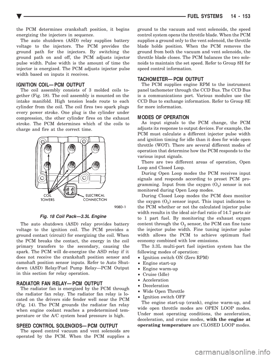
IGNITION COILÐPCM OUTPUT
The coil assembly consists of 3 molded coils to-
gether (Fig. 18). The coil assembly is mounted on the
intake manifold. High tension leads route to each
cylinder from the coil. The coil fires two spark plugs
every power stroke. One plug is the cylinder under
compression, the other cylinder fires on the exhaust
stroke. The PCM determines which of the coils to
charge and fire at the correct time.
The auto shutdown (ASD) relay provides battery
voltage to the ignition coil. The PCM provides a
ground contact (circuit) for energizing the coil. When
the PCM breaks the contact, the energy in the coil
primary transfers to the secondary, causing the
spark. The PCM will de-energize the ASD relay if it
does not receive the crankshaft position sensor and
camshaft position sensor inputs. Refer to Auto Shut-
down (ASD) Relay/Fuel Pump RelayÐPCM Output
in this section for relay operation.
RADIATOR FAN RELAYÐPCM OUTPUT
The radiator fan is energized by the PCM through
the radiator fan relay. The radiator fan relay is lo-
cated on the drivers side fender well near the PCM
(Fig. 14). The PCM grounds the radiator fan relay
when engine coolant reaches a predetermined tem-
perature or the A/C system head pressure is high.
SPEED CONTROL SOLENOIDSÐPCM OUTPUT
The speed control vacuum and vent solenoids are
operated by the PCM. When the PCM supplies a ground to the vacuum and vent solenoids, the speed
control system opens the throttle blade. When the PCM
supplies a ground only to the vent solenoid, the throttle
blade holds position. When the PCM removes the
ground from both the vacuum and vent solenoids, the
throttle blade closes. The PCM balances the two sole-
noids to maintain the set speed. Refer to Group 8H for
speed control information.
TACHOMETERÐPCM OUTPUT
The PCM supplies engine RPM to the instrument
panel tachometer through the CCD Bus. The CCD Bus
is a communications port. Various modules use the
CCD Bus to exchange information. Refer to Group 8E
for more information.
MODES OF OPERATION
As input signals to the PCM change, the PCM
adjusts its response to output devices. For example, the
PCM must calculate a different injector pulse width
and ignition timing for idle than it does for wide open
throttle (WOT). There are several different modes of
operation that determine how the PCM responds to the
various input signals. There are two different areas of operation, Open
Loop and Closed Loop. During Open Loop modes the PCM receives input
signals and responds according to preset PCM pro-
gramming. Input from the oxygen (O
2) sensor is not
monitored during Open Loop modes. During Closed Loop modes the PCM does monitor
the oxygen (O
2) sensor input. This input indicates to
the PCM whether or not the calculated injector pulse
width results in the ideal air-fuel ratio of 14.7 parts air
to 1 part fuel. By monitoring the exhaust oxygen
content through the O
2sensor, the PCM can fine tune
the injector pulse width. Fine tuning injector pulse
width allows the PCM to achieve optimum fuel
economy combined with low emissions. The 3.3L multi-port fuel injection system has the
following modes of operation:
² Ignition switch ON (Zero RPM)
² Engine start-up
² Engine warm-up
² Cruise (Idle)
² Acceleration
² Deceleration
² Wide Open Throttle
² Ignition switch OFF
The engine start-up (crank), engine warm-up, and
wide open throttle modes are OPEN LOOP modes.
Under most operating conditions, the acceleration,
deceleration, and cruise modes, with the engine at
operating temperature are CLOSED LOOP modes.
Fig. 18 Coil PackÐ3.3L Engine
Ä FUEL SYSTEMS 14 - 153
Page 1894 of 2438
IGNITION SWITCH ON (ZERO RPM) MODE When the multi-port fuel injection system is acti-
vated by the ignition switch, the following actions oc-
cur:
² The PCM determines atmospheric air pressure
from the MAP sensor input to determine basic fuel
strategy.
² The PCM monitors the coolant temperature sensor
and throttle position sensor input. The PCM modifies
fuel strategy based on this input. When the key is in the ON position and the engine
is not running (zero rpm), the auto shutdown (ASD)
relay and fuel pump relay are not energized. There-
fore battery voltage is not supplied to the fuel pump,
ignition coil, fuel injectors or oxygen sensor heating
element.
ENGINE START-UP MODE
This is an OPEN LOOP mode. The following ac-
tions occur when the starter motor is engaged. If the PCM receives the camshaft position sensor
and crankshaft position sensor signals, it energizes
the auto shutdown (ASD) relay and fuel pump relay.
These relays supply battery voltage to the fuel pump,
fuel injectors, ignition coil, and oxygen sensor heat-
ing element. If the PCM does not receive the cam-
shaft position sensor and crankshaft position sensor
signals within approximately one second, it de-ener-
gizes the ASD relay and fuel pump relay. The PCM energizes all six injectors until it deter-
mines crankshaft position from the camshaft position
sensor and crankshaft position sensor signals. The
PCM determines crankshaft position within 1 engine
revolution. After determining crankshaft position, the PCM
begins energizing the injectors in sequence. The PCM
adjusts injector pulse width and controls injector syn-
chronization by turning the individual ground paths
to the injectors On and Off. When the engine idles within 664 RPM of its tar-
get RPM, the PCM compares current MAP sensor
value with the atmospheric pressure value received
during the Ignition Switch On (Zero RPM) mode. If
the PCM does not detect a minimum difference be-
tween the two values, it sets a MAP fault into mem-
ory. Once the ASD and fuel pump relays have been en-
ergized, the PCM:
² Determines injector pulse width based on battery
voltage, coolant temperature, engine rpm and the
number of engine revolutions since cranking was ini-
tiated.
ENGINE WARM-UP MODE This is a OPEN LOOP mode. The following inputs
are received by the PCM:
² engine coolant temperature ²
manifold absolute pressure (MAP)
² engine speed (crankshaft position sensor)
² throttle position
² A/C switch
² battery voltage
The PCM adjusts injector pulse width and controls
injector synchronization by turning the individual
ground paths to the injectors On and Off. The PCM adjusts ignition timing and engine idle
speed. Engine idle speed is adjusted through the idle
air control motor.
CRUISE OR IDLE MODE
When the engine is at operating temperature this
is a CLOSED LOOP mode. During cruising speed the
following inputs are received by the PCM:
² engine coolant temperature
² manifold absolute pressure
² engine speed (crankshaft position sensor)
² throttle position
² exhaust gas oxygen content
² A/C control positions
² battery voltage
The PCM adjusts injector pulse width and controls
injector synchronization by turning the individual
ground paths to the injectors On and Off. The PCM adjusts engine idle speed and ignition
timing. The PCM adjusts the air/fuel ratio according
to the oxygen content in the exhaust gas.
ACCELERATION MODE This is a CLOSED LOOP mode. The PCM recog-
nizes an abrupt increase in throttle position or MAP
pressure as a demand for increased engine output
and vehicle acceleration. The PCM increases injector
pulse width in response to increased fuel demand.
DECELERATION MODE This is a CLOSED LOOP mode. During decelera-
tion the following inputs are received by the PCM:
² engine coolant temperature
² manifold absolute pressure
² engine speed
² throttle position
² exhaust gas oxygen content
² A/C control positions
² battery voltage
The PCM may receive a closed throttle input from
the throttle position sensor (TPS) when it senses an
abrupt decrease in manifold pressure. This indicates
a hard deceleration. The PCM will reduce injector
pulse width. This helps maintain better control of the
air-fuel mixture (as sensed through the O
2sensor).
During a closed throttle deceleration condition, the
PCM grounds the exhaust gas recirculation (EGR)
solenoid. When the solenoid is grounded, EGR func-
tion stops.
14 - 154 FUEL SYSTEMS Ä