manual transmission CHEVROLET DYNASTY 1993 Owner's Guide
[x] Cancel search | Manufacturer: CHEVROLET, Model Year: 1993, Model line: DYNASTY, Model: CHEVROLET DYNASTY 1993Pages: 2438, PDF Size: 74.98 MB
Page 2057 of 2438
first separator plate and watch carefully for the pis-
ton to move forward. The piston should return to its
original position after the air pressure is removed.
UNDERDRIVE CLUTCH
Because this clutch piston cannot be seen, its oper-
ation is checked by function. Air pressure is applied
to the low/reverse and the 2/4 clutches. This locks
the output shaft. Use a piece of rubber hose wrapped
around the input shaft and a pair of clamp-on pliers
to turn the input shaft. Next apply air pressure to
the underdrive clutch. The input shaft should not ro-
tate with hand torque. Release the air pressure and
confirm that the input shaft will rotate.
FLUID LEAKAGE-TORQUE CONVERTER HOUSING
AREA
(1) Check for source of leakage.
Since fluid leakage at or around the torque con-
verter area may originate from an engine oil leak,
the area should be examined closely. Factory fill
fluid is dyed red and, therefore, can be distinguished
from engine oil. (2) Prior to removing the transaxle, perform the
following checks: When leakage is determined to originate from the
transaxle, check fluid level prior to removal of the
transaxle and torque converter. High oil level can result in oil leakage out the vent
in the manual shaft. If the fluid level is high, adjust
to proper level. After performing this operation, inspect for leak-
age. If a leak persists, perform the following opera-
tion on the vehicle to determine if it is the torque
converter or transaxle that is leaking.
LEAKAGE TEST PROBE
(1) Remove torque converter housing dust shield.
(2) Clean the inside of torque converter housing
(lower area) as dry as possible. A solvent spray fol-
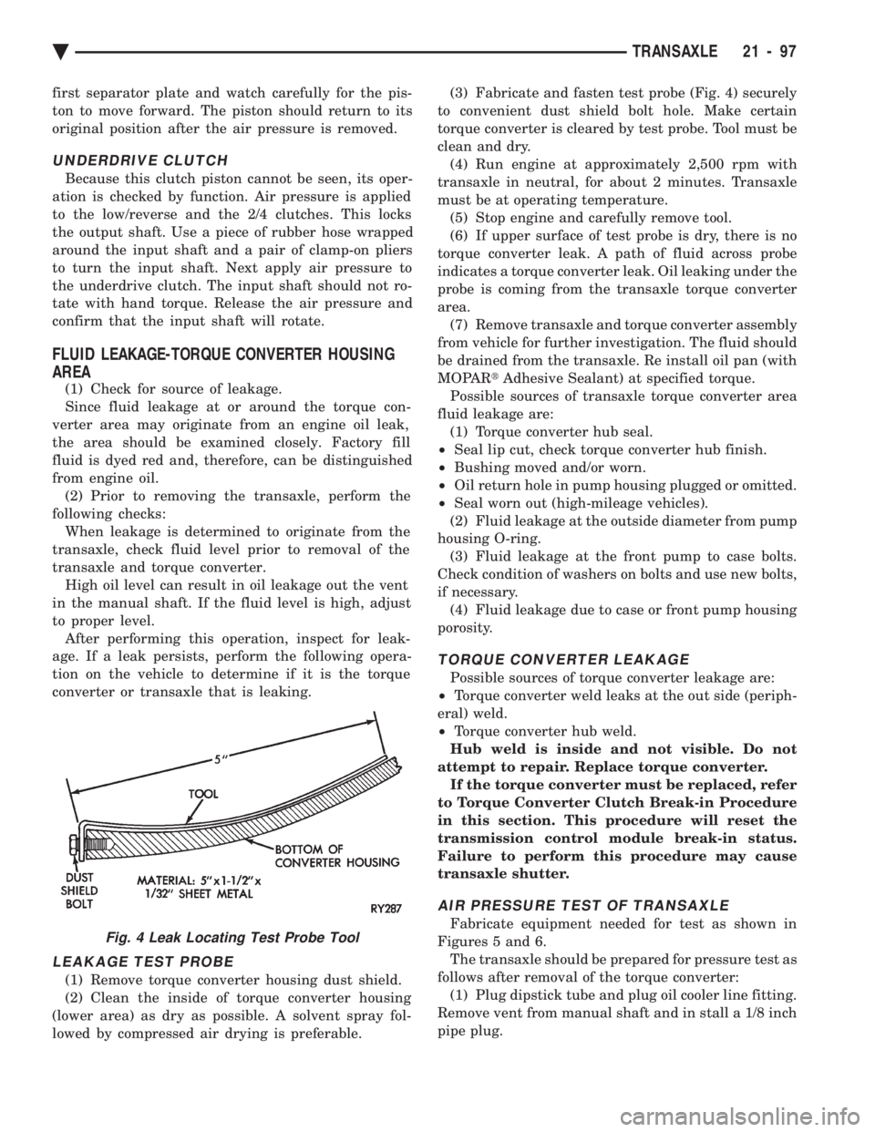
lowed by compressed air drying is preferable. (3) Fabricate and fasten test probe (Fig. 4) securely
to convenient dust shield bolt hole. Make certain
torque converter is cleared by test probe. Tool must be
clean and dry. (4) Run engine at approximately 2,500 rpm with
transaxle in neutral, for about 2 minutes. Transaxle
must be at operating temperature. (5) Stop engine and carefully remove tool.
(6) If upper surface of test probe is dry, there is no
torque converter leak. A path of fluid across probe
indicates a torque converter leak. Oil leaking under the
probe is coming from the transaxle torque converter
area. (7) Remove transaxle and torque converter assembly
from vehicle for further investigation. The fluid should
be drained from the transaxle. Re install oil pan (with
MOPAR tAdhesive Sealant) at specified torque.
Possible sources of transaxle torque converter area
fluid leakage are: (1) Torque converter hub seal.
² Seal lip cut, check torque converter hub finish.
² Bushing moved and/or worn.
² Oil return hole in pump housing plugged or omitted.
² Seal worn out (high-mileage vehicles).
(2) Fluid leakage at the outside diameter from pump
housing O-ring. (3) Fluid leakage at the front pump to case bolts.
Check condition of washers on bolts and use new bolts,
if necessary. (4) Fluid leakage due to case or front pump housing
porosity.
TORQUE CONVERTER LEAKAGE
Possible sources of torque converter leakage are:
² Torque converter weld leaks at the out side (periph-
eral) weld.
² Torque converter hub weld.
Hub weld is inside and not visible. Do not
attempt to repair. Replace torque converter. If the torque converter must be replaced, refer
to Torque Converter Clutch Break-in Procedure
in this section. This procedure will reset the
transmission control module break-in status.
Failure to perform this procedure may cause
transaxle shutter.
AIR PRESSURE TEST OF TRANSAXLE
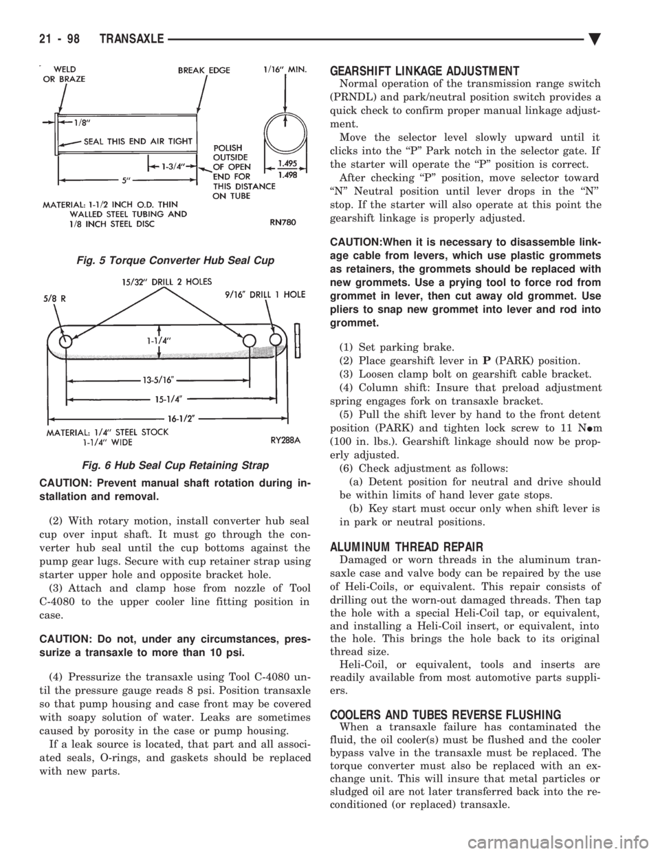
Fabricate equipment needed for test as shown in
Figures 5 and 6. The transaxle should be prepared for pressure test as
follows after removal of the torque converter: (1) Plug dipstick tube and plug oil cooler line fitting.
Remove vent from manual shaft and in stall a 1/8 inch
pipe plug.Fig. 4 Leak Locating Test Probe Tool
Ä TRANSAXLE 21 - 97
Page 2058 of 2438
CAUTION: Prevent manual shaft rotation during in-
stallation and removal. (2) With rotary motion, install converter hub seal
cup over input shaft. It must go through the con-
verter hub seal until the cup bottoms against the
pump gear lugs. Secure with cup retainer strap using
starter upper hole and opposite bracket hole. (3) Attach and clamp hose from nozzle of Tool
C-4080 to the upper cooler line fitting position in
case.
CAUTION: Do not, under any circumstances, pres-
surize a transaxle to more than 10 psi.
(4) Pressurize the transaxle using Tool C-4080 un-
til the pressure gauge reads 8 psi. Position transaxle
so that pump housing and case front may be covered
with soapy solution of water. Leaks are sometimes
caused by porosity in the case or pump housing. If a leak source is located, that part and all associ-
ated seals, O-rings, and gaskets should be replaced
with new parts.
GEARSHIFT LINKAGE ADJUSTMENT
Normal operation of the transmission range switch
(PRNDL) and park/neutral position switch provides a
quick check to confirm proper manual linkage adjust-
ment. Move the selector level slowly upward until it
clicks into the ``P'' Park notch in the selector gate. If
the starter will operate the ``P'' position is correct. After checking ``P'' position, move selector toward
``N'' Neutral position until lever drops in the ``N''
stop. If the starter will also operate at this point the
gearshift linkage is properly adjusted.
CAUTION:When it is necessary to disassemble link-
age cable from levers, which use plastic grommets
as retainers, the grommets should be replaced with
new grommets. Use a prying tool to force rod from
grommet in lever, then cut away old grommet. Use
pliers to snap new grommet into lever and rod into
grommet.
(1) Set parking brake.
(2) Place gearshift lever in P(PARK) position.
(3) Loosen clamp bolt on gearshift cable bracket.
(4) Column shift: Insure that preload adjustment
spring engages fork on transaxle bracket. (5) Pull the shift lever by hand to the front detent
position (PARK) and tighten lock screw to 11 N Im
(100 in. lbs.). Gearshift linkage should now be prop-
erly adjusted. (6) Check adjustment as follows:(a) Detent position for neutral and drive should
be within limits of hand lever gate stops. (b) Key start must occur only when shift lever is
in park or neutral positions.
ALUMINUM THREAD REPAIR
Damaged or worn threads in the aluminum tran-
saxle case and valve body can be repaired by the use
of Heli-Coils, or equivalent. This repair consists of
drilling out the worn-out damaged threads. Then tap
the hole with a special Heli-Coil tap, or equivalent,
and installing a Heli-Coil insert, or equivalent, into
the hole. This brings the hole back to its original
thread size. Heli-Coil, or equivalent, tools and inserts are
readily available from most automotive parts suppli-
ers.
COOLERS AND TUBES REVERSE FLUSHING
When a transaxle failure has contaminated the
fluid, the oil cooler(s) must be flushed and the cooler
bypass valve in the transaxle must be replaced. The
torque converter must also be replaced with an ex-
change unit. This will insure that metal particles or
sludged oil are not later transferred back into the re-
conditioned (or replaced) transaxle.
Fig. 5 Torque Converter Hub Seal Cup
Fig. 6 Hub Seal Cup Retaining Strap
21 - 98 TRANSAXLE Ä
Page 2060 of 2438
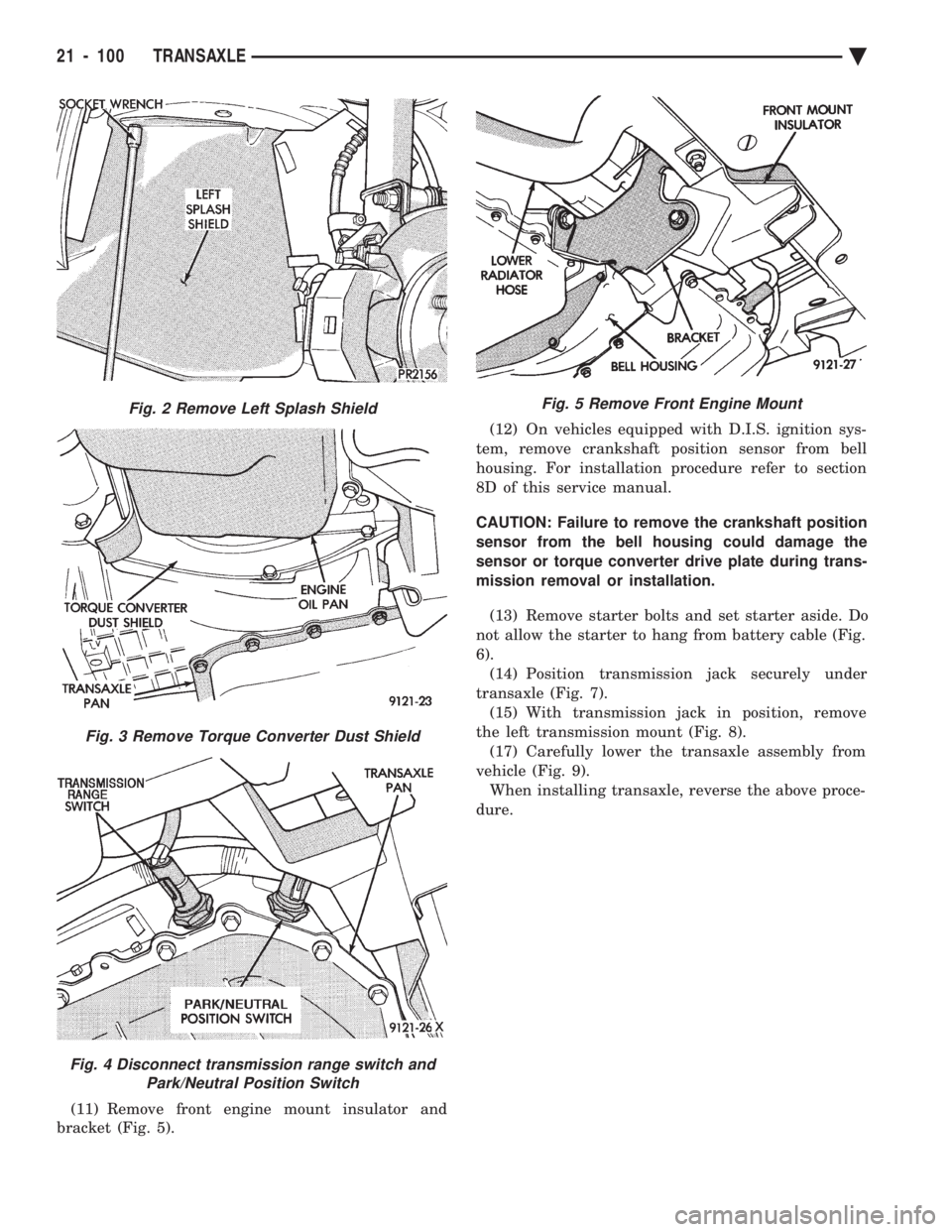
(11) Remove front engine mount insulator and
bracket (Fig. 5). (12) On vehicles equipped with D.I.S. ignition sys-
tem, remove crankshaft position sensor from bell
housing. For installation procedure refer to section
8D of this service manual.
CAUTION: Failure to remove the crankshaft position
sensor from the bell housing could damage the
sensor or torque converter drive plate during trans-
mission removal or installation.
(13) Remove starter bolts and set starter aside. Do
not allow the starter to hang from battery cable (Fig.
6). (14) Position transmission jack securely under
transaxle (Fig. 7). (15) With transmission jack in position, remove
the left transmission mount (Fig. 8). (17) Carefully lower the transaxle assembly from
vehicle (Fig. 9). When installing transaxle, reverse the above proce-
dure.
Fig. 2 Remove Left Splash Shield
Fig. 3 Remove Torque Converter Dust Shield
Fig. 4 Disconnect transmission range switch and Park/Neutral Position Switch
Fig. 5 Remove Front Engine Mount
21 - 100 TRANSAXLE Ä
Page 2062 of 2438
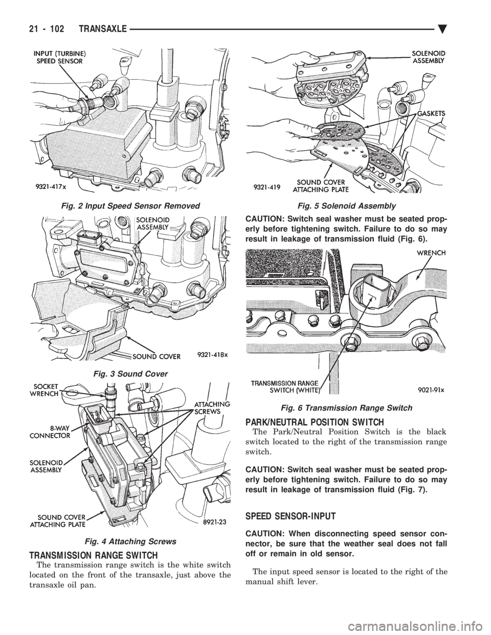
TRANSMISSION RANGE SWITCH
The transmission range switch is the white switch
located on the front of the transaxle, just above the
transaxle oil pan. CAUTION: Switch seal washer must be seated prop-
erly before tightening switch. Failure to do so may
result in leakage of transmission fluid (Fig. 6).
PARK/NEUTRAL POSITION SWITCH
The Park/Neutral Position Switch is the black
switch located to the right of the transmission range
switch.
CAUTION: Switch seal washer must be seated prop-
erly before tightening switch. Failure to do so may
result in leakage of transmission fluid (Fig. 7).
SPEED SENSOR-INPUT
CAUTION: When disconnecting speed sensor con-
nector, be sure that the weather seal does not fall
off or remain in old sensor.
The input speed sensor is located to the right of the
manual shift lever.
Fig. 2 Input Speed Sensor Removed
Fig. 3 Sound Cover
Fig. 4 Attaching Screws
Fig. 5 Solenoid Assembly
Fig. 6 Transmission Range Switch
21 - 102 TRANSAXLE Ä
Page 2063 of 2438
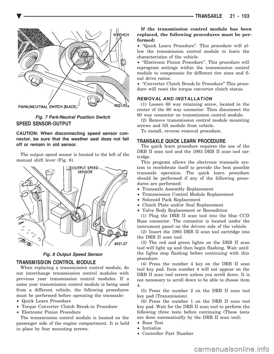
SPEED SENSOR-OUTPUT
CAUTION: When disconnecting speed sensor con-
nector, be sure that the weather seal does not fall
off or remain in old sensor. The output speed sensor is located to the left of the
manual shift lever (Fig. 8).
TRANSMISSION CONTROL MODULE
When replacing a transmission control module, do
not interchange transmission control modules with
previous year transmission control modules. If a
same year transmission control module is being used
from a different vehicle, the following procedures
must be performed before operating the transaxle:
² Quick Learn Procedure
² Torque Converter Clutch Break-in Procedure
² Electronic Pinion Procedure
The transmission control module is located on the
passenger side of the engine compartment. It is held
in place by four mounting screws. If the transmission control module has been
replaced, the following procedures must be per-
formed:
² ``Quick Learn Procedure''. This procedure will al-
low the transmission control module to learn the
characteristics of the vehicle.
² ``Electronic Pinion Procedure''. This procedure will
reprogram settings within the transmission control
module to compensate for different tire sizes and fi-
nal drive ratios.
² ``Converter Clutch Break-In Procedure'' This proce-
dure will reset the torque converter clutch status.
REMOVAL AND INSTALLATION
(1) Loosen 60 way retaining screw, located in the
center of the 60 way connector. Then disconnect the
60 way connector on transmission control module. (2) Remove transmission control module mounting
screws and lift module from vehicle. To install, reverse removal procedure.
TRANSAXLE QUICK LEARN PROCEDURE
The quick learn procedure requires the use of the
DRB II scan tool and the 1993 DRB II scan tool car-
tridge. This program allows the electronic transaxle sys-
tem to recelebrate itself to provide the best possible
transaxle operation. The quick learn procedure
should be performed if any of the following proce-
dures are performed:
² Transaxle Assembly Replacement
² Transmission Control Module Replacement
² Solenoid Pack Replacement
² Clutch Plate and/or Seal Replacement
² Valve Body Replacement or Recondition
(1) Plug the DRB II scan tool into the blue CCD
Buss connector. The connector is located under the
instrument panel on the drivers side of the vehicle. (2) Insert the 1993 DRB II scan tool cartridge into
the DRB II scan tool. (3) The red and green lights on the DRB II scan
tool will light up and then begin flashing. Wait until
the lights stop flashing before continuing with this
procedure. (4) Press the number 4 key on the DRB II scan
tool key pad. Item number 4 will not appear on the
DRB II scan tool screen unless you scroll down. It is
not necessary to scroll down to be able to choose item
4. (5) Press the number 2 on the DRB II scan tool
key pad (Transmission). (6) Press the number 1 on the DRB II scan tool
key pad. Wait for the DRB II scan tool to perform the
following three tests before continuing (These tests
are done automatically by the DRB II scan tool).
² Buss Test
² Initialize
² Controller Part Number
Fig. 7 Park/Neutral Position Switch
Fig. 8 Output Speed Sensor
Ä TRANSAXLE 21 - 103
Page 2105 of 2438
41TE ON-BOARD DIAGNOSTICS INDEX
page page
CCD Bus .............................. 145
Diagnostic Trouble Code Charts ............ 146
Diagnostic Trouble Codes ................. 145
DRB II Scan Tool ....................... 146 General Information
...................... 145
Limp-In Mode .......................... 145
On-Board Diagnostics Information ........... 145
GENERAL INFORMATION
The information in this manual is designed to help
the technician understand and repair the transaxle
with the aid of the built in on-board diagnostics. Chrysler Corporation has developed a com-
plete set of diagnostic manuals which cover the
diagnosis of the 41TE transaxle. They have been
designed to make transaxle diagnosis accurate
and simple. Use these manuals with the DRB II
scan tool and the latest cartridge, when diagnos-
ing transaxle problems.
ON-BOARD DIAGNOSTICS INFORMATION
The 41TE transaxle is controlled and monitored by
the transmission control module. The transmission
control module monitors critical input and output
circuits within the transaxle. Some circuits are tested continuously; others are
checked only under certain conditions. Each circuit
monitored by the transmission control module has a
corresponding fault message assigned to it that can be
read with the DRB II scan tool. If the on-board diagnostic system senses that one of
the circuits is malfunctioning, the corresponding code
is stored in memory. If the malfunction goes away after
the code is stored, the transmission control module will
erase the code after 75 key cycles.
CCD BUS
In order to diagnose the 41TE transaxle, diagnostic
trouble codes in the transmission control module's
memory should be read. Use the Diagnostic Readout
Box (DRB II) scan tool to read codes. If more than one
diagnostic trouble code exists, diagnostic priority
should be given to the most recent code. With CCD bus
bias and communication problems, the DRB II scan
tool displays an appropriate message. Diagnostic
trouble codes might not be accessible until the bus
problem is fixed. The following is a list of probable
causes for a bus problem:
² Open or short to ground/battery in either or both
CCD bus wires (pins 4 and 43).
² Open or short to ground/battery in either or both
41TE transaxle's bias wires (pin 5 and 44) on vehicles
requiring the transaxle to bias the bus.
² Open or short to ground/battery in the diagnostic
connector bus wire. ²
Internal failure of any module connected to the bus.
The CCD bus should have 2.5 volts (+2.5 volts on
CCD+ and -2.5 volts on CCD-). The bus error message displayed by the DRB II scan
tool should be helpful in diagnosing the CCD bus. For more information on diagnosing CCD bus prob-
lems, refer to the 1993 Diagnostic Procedures Manual
(non-communication with the CCD bus). All other
problems refer to the 1993 Body Vehicle Communica-
tions Diagnostic Procedures Manual.
DIAGNOSTIC TROUBLE CODES
Diagnostic Trouble Codes are two-digit numbers that
identify which circuit is malfunctioning. A code can be
set for hydraulic and mechanical reasons as well as for
electrical problems. In most cases, codes do not pin-
point which specific component is defective. Diagnostic trouble codes can only be read with
the use of the DRB II scan tool or equivalent.
HARD FAULTS
Any Diagnostic trouble code that comes back within
3 engine starts (reset count 3 or less) is a ``Hard Fault''.
This means that the defect is there every time the
transmission control module checks that circuit.
SOFT FAULTS
A ``Soft Fault'' is one that occurs intermittently. It is
not there every time the transmission control module
checks the circuit. Most soft faults are caused by wiring
or connector problems. Intermittent defects must be
looked for under the specific conditions that caused
them.
LIMP-IN MODE
The transmission control module continuously
checks for electrical and internal transaxle problems.
When a problem is sensed, the transmission control
module stores a diagnostic trouble code. All but twelve
of these codes cause the transaxle to go into the
``Limp-in mode''. While in this mode, electrical power is
taken away from the transaxle. When this happens,
the only transaxle ranges that will function are:
Ä TRANSAXLE 21 - 145
Page 2106 of 2438
² Park
² Neutral
² Reverse
² Second Gear
No upshifts or downshifts are allowed while in the
Limp-in mode. The position of the manual valve
alone allows the three ranges that are available. Although engine performance will be reduced while
in this mode, the vehicle can be driven in for service.
DRB II SCAN TOOL
The DRB II scan tool is a diagnostic read-out box
designed by Chrysler to gain access to the on-board
diagnostics. These on-board diagnostics are found on
all Chrysler-built cars and trucks. The DRB II scan tool has a few diagnostic capabil-
ities by itself. To perform most diagnostic tests, a
program cartridge must be inserted. It contains the
diagnostic test programs. There are scan tools available from other manufac-
tures that can be used on Chrysler vehicles. How-
ever, the diagnostic test procedures in this manual
have been designed for use with the Chrysler's DRB
II scan tool. The DRB II scan tool operates by communicating
with the module of the vehicle system being tested.
To communicate with the transmission control mod-
ule, the DRB II scan tool must be connected to the blue CCD bus connector located under the instru-
ment panel. Refer to the ``Using the DRB II Scan
Tool'' manual or the Diagnostic Procedures Manual
for information on how to use the DRB II scan tool.
DIAGNOSTIC TROUBLE CODE CHARTS
Below is a brief description of what each section of
the diagnostic trouble code charts are addressing.
² DIAGNOSTIC TROUBLE CODE- Tells the code
number and name (as shown on the DRB II scan
tool).
² BACKGROUND- A brief description of the circuit
that the transmission control module is monitoring.
² WHEN CHECKED- The point of time or condition
when the transmission control module makes it's sys-
tem check.
² ARMING CONDITIONS- The parameters that
must be met before a code can be set.
² FAULT CONDITION- What the transmission con-
trol module saw that is determined to be a problem.
(ie. voltage to high or low, switch/solenoid problems)
² FAULT SET TIME- Refers to the amount of time
(in seconds) a failure must occur before a diagnostic
trouble code is set in memory.
² EFFECT- Refers to how the fault effects transaxle
operations.
² POSSIBLE CAUSE- Refers to the systems or cir-
cuits which could cause the fault to be recorded.
21 - 146 TRANSAXLE Ä
Page 2409 of 2438
These systems do not allow EGR at idle. The 2.2L/
2.5L EGR systems operate at all temperatures. The
3.0L, 3.3L and 3.8L EGR systems do not operate
when coolant temperature is below 4.5ÉC (40É)F at
start-up. These systems activate when coolant tem-
perature reaches 77ÉC (170ÉF).
EGR SYSTEM ON-BOARD DIAGNOSTICS
The powertrain control module (PCM) performs an
on-board diagnostic check of the EGR system on all
California vehicles with EGR systems. The diagnos-
tic system uses the Electric EGR Transducer (EET)
for the system tests. The diagnostic check activates only during selected
engine/driving conditions. When the conditions are
met, the PCM energizes the transducer solenoid to
disable the EGR. The PCM checks for a change in the oxygen sensor signal. If the air-fuel mixture goes
lean, the PCM will attempt to enrichen the mixture.
The PCM registers a fault if the EGR system has
failed or degraded. After registering a fault, the PCM
turns on the malfunction indicator lamp (instrument
panel Check Engine light). The malfunction indicator
lamp indicates the need for immediate service.
If a problem is indicated by the malfunction indicator
lamp and a diagnostic trouble code for the EGR system,
check for proper operation of the EGR system. Use the
System Test, EGR Gas Flow Test and EGR Diagnosis
Chart. If the EGR system tests properly, check the sys-
tem using the DRBII scan tool. Refer to On-Board Di-
agnosis in the General Diagnosis sections of Group 14.
Also, refer to the DRBII scan tool and the appropriate
Powertrain Diagnostics Procedure manual.
EXHAUST GAS RECIRCULATION (EGR) SYSTEM
TEST
WARNING: APPLY PARKING BRAKE AND/OR
BLOCK WHEELS BEFORE PERFORMING EGR SYS-
TEM TEST.
A failed or malfunctioning EGR system can cause
engine spark knock, sags or hesitation, rough idle,
and/or engine stalling. To ensure proper operation of
the EGR system, all passages and moving parts must
be free of deposits that could cause plugging or stick-
ing. Ensure system hoses do not leak. Replace leak-
ing components. Inspect hose connections between the throttle body,
intake manifold, EGR solenoid and transducer, and
EGR valve. Replace hardened, cracked, or melted
hoses. Repair or replace faulty connectors.
Check the EGR control system and EGR valve with
the engine fully warmed up and running (engine cool-
ant temperature over 150ÉF). With the transmission in
neutral and the throttle closed, allow the engine to idle
for 70 seconds. Abruptly accelerate the engine to ap-
proximately 2000 rpm, but not over 3000 rpm. The EGR
valve stem should move when accelerating the engine
(the relative position of the groove on the EGR valve
stem should change). Repeat the test several times to
confirm movement. If the EGR valve stem moves, the
control system is operating normally. If the control sys-
tem is not operating normally, refer to the EGR Diag-
nosis Chart to determine the cause.
EGR GAS FLOW TEST
The following procedure should be used to determine
if exhaust gas is flowing through the EGR system.
Connect a hand vacuum pump to the EGR valve
vacuum motor. With engine running at idle speed,
slowly apply vacuum. Engine speed should begin to
drop when applied vacuum reaches 2.0 to 3.5 inches.
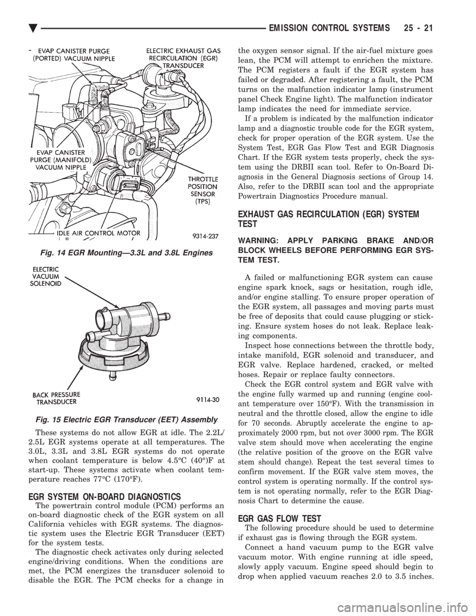
Fig. 14 EGR MountingÐ3.3L and 3.8L Engines
Fig. 15 Electric EGR Transducer (EET) Assembly
Ä EMISSION CONTROL SYSTEMS 25 - 21