seats CHEVROLET DYNASTY 1993 Owner's Guide
[x] Cancel search | Manufacturer: CHEVROLET, Model Year: 1993, Model line: DYNASTY, Model: CHEVROLET DYNASTY 1993Pages: 2438, PDF Size: 74.98 MB
Page 1605 of 2438
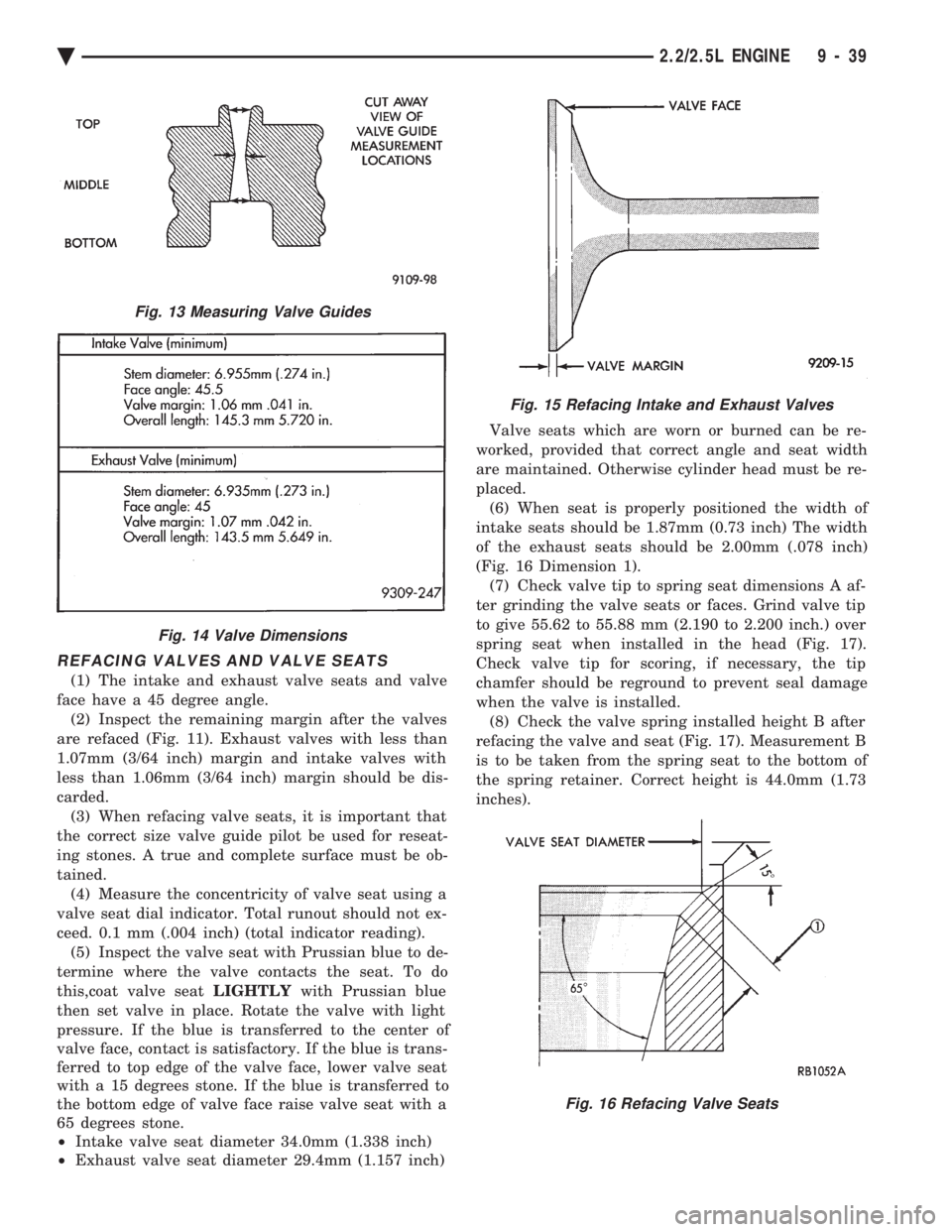
REFACING VALVES AND VALVE SEATS
(1) The intake and exhaust valve seats and valve
face have a 45 degree angle. (2) Inspect the remaining margin after the valves
are refaced (Fig. 11). Exhaust valves with less than
1.07mm (3/64 inch) margin and intake valves with
less than 1.06mm (3/64 inch) margin should be dis-
carded. (3) When refacing valve seats, it is important that
the correct size valve guide pilot be used for reseat-
ing stones. A true and complete surface must be ob-
tained. (4) Measure the concentricity of valve seat using a
valve seat dial indicator. Total runout should not ex-
ceed. 0.1 mm (.004 inch) (total indicator reading). (5) Inspect the valve seat with Prussian blue to de-
termine where the valve contacts the seat. To do
this,coat valve seat LIGHTLYwith Prussian blue
then set valve in place. Rotate the valve with light
pressure. If the blue is transferred to the center of
valve face, contact is satisfactory. If the blue is trans-
ferred to top edge of the valve face, lower valve seat
with a 15 degrees stone. If the blue is transferred to
the bottom edge of valve face raise valve seat with a
65 degrees stone.
² Intake valve seat diameter 34.0mm (1.338 inch)
² Exhaust valve seat diameter 29.4mm (1.157 inch) Valve seats which are worn or burned can be re-
worked, provided that correct angle and seat width
are maintained. Otherwise cylinder head must be re-
placed. (6) When seat is properly positioned the width of
intake seats should be 1.87mm (0.73 inch) The width
of the exhaust seats should be 2.00mm (.078 inch)
(Fig. 16 Dimension 1). (7) Check valve tip to spring seat dimensions A af-
ter grinding the valve seats or faces. Grind valve tip
to give 55.62 to 55.88 mm (2.190 to 2.200 inch.) over
spring seat when installed in the head (Fig. 17).
Check valve tip for scoring, if necessary, the tip
chamfer should be reground to prevent seal damage
when the valve is installed. (8) Check the valve spring installed height B after
refacing the valve and seat (Fig. 17). Measurement B
is to be taken from the spring seat to the bottom of
the spring retainer. Correct height is 44.0mm (1.73
inches).
Fig. 13 Measuring Valve Guides
Fig. 14 Valve Dimensions
Fig. 15 Refacing Intake and Exhaust Valves
Fig. 16 Refacing Valve Seats
Ä 2.2/2.5L ENGINE 9 - 39
Page 1606 of 2438
VALVE GEAR REASSEMBLY AFTER VALVE SERVICE
(1) Coat valve stems with lubrication oil and insert
in cylinder head. (2) Install new valve stem seals on all valves. The
valve stem seals should be pushed firmly and
squarely over valve guide. The lower edge of the seal
should be resting on the valve guide boss. (3) Install valve spring seats and springs and re-
tainers. Compress valve springs only enough to in-
stall locks, taking care not to misalign the direction
of compression. Nicked valve stems may result from
misalignment of the valve spring compressor.
CAUTION: When depressing the valve spring retain-
ers with Valve Spring Compressor Tool C-3422-B
with adopters 6537 and 6526 (Fig. 11) the locks can
become dislocated. Check to make sure both locks
are in their correct location after removing tool.
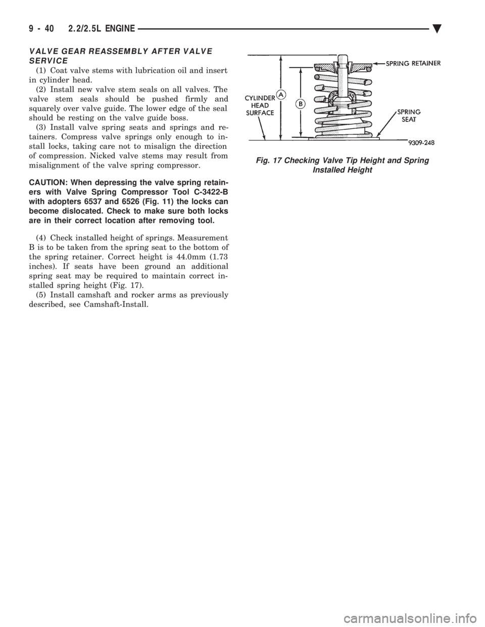
(4) Check installed height of springs. Measurement
B is to be taken from the spring seat to the bottom of
the spring retainer. Correct height is 44.0mm (1.73
inches). If seats have been ground an additional
spring seat may be required to maintain correct in-
stalled spring height (Fig. 17). (5) Install camshaft and rocker arms as previously
described, see Camshaft-Install.
Fig. 17 Checking Valve Tip Height and Spring Installed Height
9 - 40 2.2/2.5L ENGINE Ä
Page 1671 of 2438
(3) Before removing valves, remove any burrs
from valve stem lock grooves to prevent damage
to the valve guides. Identify valves to insure instal-
lation in original location.
VALVE INSPECTION
(1) Clean valves thoroughly and discard burned,
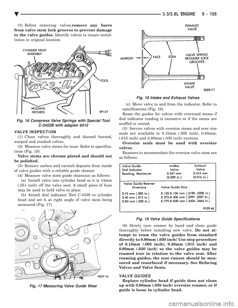
warped and cracked valves. (2) Measure valve stems for wear. Refer to specifica-
tions (Fig. 19). Valve stems are chrome plated and should not
be polished. (3) Remove carbon and varnish deposits from inside
of valve guides with a reliable guide cleaner. (4) Measure valve stem guide clearance as follows:(a) Install valve into cylinder head so it is 14mm
(.551 inch) off the valve seat. A small piece of hose
may be used to hold valve in place. (b) Attach dial indicator Tool C-3339 to cylinder
head and set it at right angle of valve stem being
measured (Fig. 17). (c) Move valve to and from the indicator. Refer to
specifications (Fig. 19).
Ream the guides for valves with oversized stems if
dial indicator reading is excessive or if the stems are
scuffed or scored. (5) Service valves with oversize stems and over size
seals are available in 0.15mm (.005 inch), 0.40mm,
(.015 inch) and 0.80mm (.030 inch) oversize. Oversize seals must be used with oversize
valves. Reamers to accommodate the oversize valve stem are
as follows:
(6) Slowly turn reamer by hand and clean guide
thoroughly before installing new valve. Do not at-
tempt to ream the valve guides from standard
directly to 0.80mm (.030 inch) Use step procedure
of 0.15mm (.005 inch), 0.40mm (.015 inch) and
0.80mm (.030 inch) so the valve guides may be
reamed true in relation to the valve seat. After
reaming guides, the seat runout should be mea-
sured and resurfaced if necessary. See Refacing
Valves and Valve Seats.
VALVE GUIDES
Replace cylinder head if guide does not clean
up with 0.80mm (.030 inch) oversize reamer, or if
guide is loose in cylinder head.
Fig. 18 Intake and Exhaust Valves
Fig. 19 Valve Guide Specifications
Fig. 16 Compress Valve Springs with Special Tool C-3422B with adapter 6412
Fig. 17 Measuring Valve Guide Wear
Ä 3.3/3.8L ENGINE 9 - 105
Page 1672 of 2438
REFACING VALVES AND VALVE SEATS
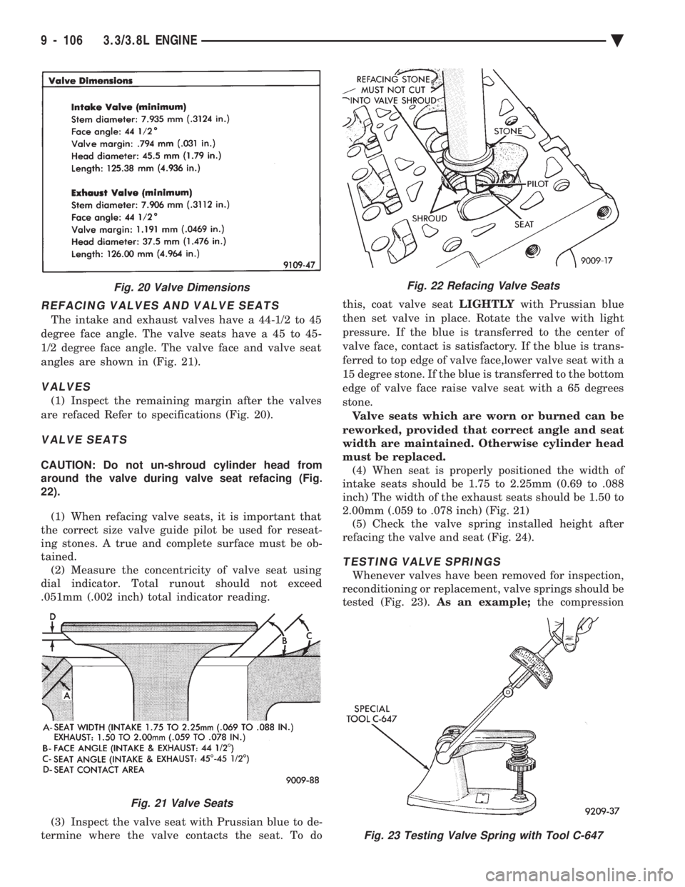
The intake and exhaust valves have a 44-1/2 to 45
degree face angle. The valve seats have a 45 to 45-
1/2 degree face angle. The valve face and valve seat
angles are shown in (Fig. 21).
VALVES
(1) Inspect the remaining margin after the valves
are refaced Refer to specifications (Fig. 20).
VALVE SEATS
CAUTION: Do not un-shroud cylinder head from
around the valve during valve seat refacing (Fig.
22).
(1) When refacing valve seats, it is important that
the correct size valve guide pilot be used for reseat-
ing stones. A true and complete surface must be ob-
tained. (2) Measure the concentricity of valve seat using
dial indicator. Total runout should not exceed
.051mm (.002 inch) total indicator reading.
(3) Inspect the valve seat with Prussian blue to de-
termine where the valve contacts the seat. To do this, coat valve seat
LIGHTLYwith Prussian blue
then set valve in place. Rotate the valve with light
pressure. If the blue is transferred to the center of
valve face, contact is satisfactory. If the blue is trans-
ferred to top edge of valve face,lower valve seat with a
15 degree stone. If the blue is transferred to the bottom
edge of valve face raise valve seat with a 65 degrees
stone. Valve seats which are worn or burned can be
reworked, provided that correct angle and seat
width are maintained. Otherwise cylinder head
must be replaced. (4) When seat is properly positioned the width of
intake seats should be 1.75 to 2.25mm (0.69 to .088
inch) The width of the exhaust seats should be 1.50 to
2.00mm (.059 to .078 inch) (Fig. 21) (5) Check the valve spring installed height after
refacing the valve and seat (Fig. 24).
TESTING VALVE SPRINGS
Whenever valves have been removed for inspection,
reconditioning or replacement, valve springs should be
tested (Fig. 23). As an example; the compression
Fig. 23 Testing Valve Spring with Tool C-647
Fig. 20 Valve Dimensions
Fig. 21 Valve Seats
Fig. 22 Refacing Valve Seats
9 - 106 3.3/3.8L ENGINE Ä
Page 1673 of 2438
length of the spring to be tested is 33.34mm (1-5/16
inches). Turn table of Tool C-647 until surface is in line
with the 33.34mm (1-5/16 inch) mark on the threaded
stud and the zero mark on the front. Place spring over
stud on the table and lift compressing lever to set tone
device. Pull on torque wrench until ping is heard. Take
reading on torque wrench at this instant. Multiply this
reading by two. This will give the spring load at test
length. Fractional measurements are indicated on the
table for finer adjustments. Refer to specifications to
obtain specified height and allowable tensions. Discard
the springs that do not meet specifications.
VALVE INSTALLATION
(1) Coat valve stems with clean engine oil and insert
them in cylinder head. (2) Check valve tip to spring seat dimension A after
grinding the valve seats or faces. Grind valve tip to give
49.541 to 51.271 mm (1.950 to 2.018 inch.) over spring
seat when installed in the head (Fig. 17). Check valve
tip for scoring, if necessary, the tip chamfer should be
reground to prevent seal damage when the valve is
installed. (3) Install new cup seals on all valve stems and over
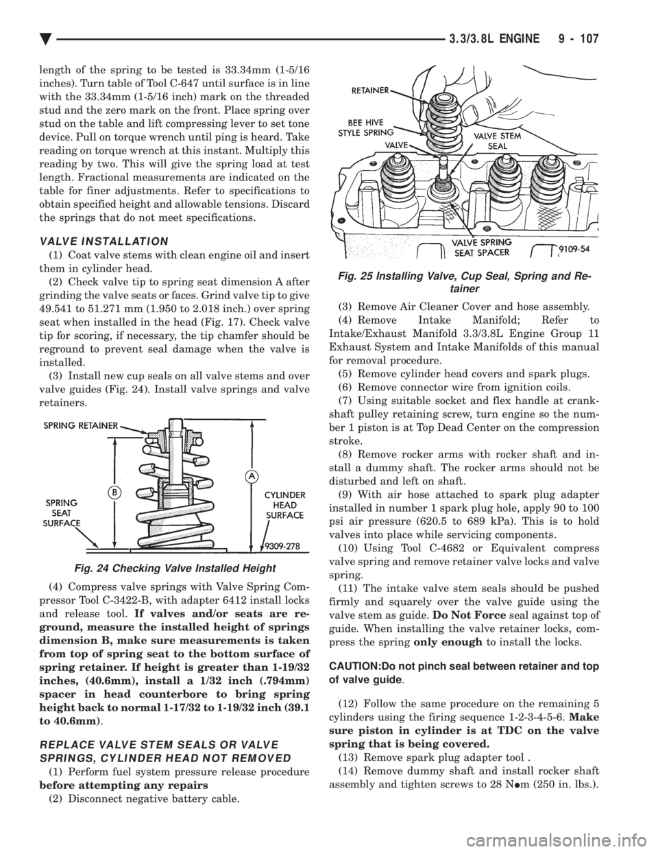
valve guides (Fig. 24). Install valve springs and valve
retainers.
(4) Compress valve springs with Valve Spring Com-
pressor Tool C-3422-B, with adapter 6412 install locks
and release tool. If valves and/or seats are re-
ground, measure the installed height of springs
dimension B, make sure measurements is taken
from top of spring seat to the bottom surface of
spring retainer. If height is greater than 1-19/32
inches, (40.6mm), install a 1/32 inch (.794mm)
spacer in head counterbore to bring spring
height back to normal 1-17/32 to 1-19/32 inch (39.1
to 40.6mm) .
REPLACE VALVE STEM SEALS OR VALVE
SPRINGS, CYLINDER HEAD NOT REMOVED
(1) Perform fuel system pressure release procedure
before attempting any repairs (2) Disconnect negative battery cable. (3) Remove Air Cleaner Cover and hose assembly.
(4) Remove Intake Manifold; Refer to
Intake/Exhaust Manifold 3.3/3.8L Engine Group 11
Exhaust System and Intake Manifolds of this manual
for removal procedure. (5) Remove cylinder head covers and spark plugs.
(6) Remove connector wire from ignition coils.
(7) Using suitable socket and flex handle at crank-
shaft pulley retaining screw, turn engine so the num-
ber 1 piston is at Top Dead Center on the compression
stroke. (8) Remove rocker arms with rocker shaft and in-
stall a dummy shaft. The rocker arms should not be
disturbed and left on shaft. (9) With air hose attached to spark plug adapter
installed in number 1 spark plug hole, apply 90 to 100
psi air pressure (620.5 to 689 kPa). This is to hold
valves into place while servicing components. (10) Using Tool C-4682 or Equivalent compress
valve spring and remove retainer valve locks and valve
spring. (11) The intake valve stem seals should be pushed
firmly and squarely over the valve guide using the
valve stem as guide. Do Not Forceseal against top of
guide. When installing the valve retainer locks, com-
press the spring only enoughto install the locks.
CAUTION:Do not pinch seal between retainer and top
of valve guide .
(12) Follow the same procedure on the remaining 5
cylinders using the firing sequence 1-2-3-4-5-6. Make
sure piston in cylinder is at TDC on the valve
spring that is being covered. (13) Remove spark plug adapter tool .
(14) Remove dummy shaft and install rocker shaft
assembly and tighten screws to 28 N Im (250 in. lbs.).
Fig. 24 Checking Valve Installed Height
Fig. 25 Installing Valve, Cup Seal, Spring and Re-
tainer
Ä 3.3/3.8L ENGINE 9 - 107
Page 2154 of 2438
WHEELS SERVICE PROCEDURES INDEX
page page
General Information ........................ 6
Tire and Wheel Balance .................... 6
Tire and Wheel Run Out .................... 7 Wheel Installation
......................... 6
Wheel Replacement ....................... 6
GENERAL INFORMATION
Original equipment wheels are designed for proper
operation at all loads up to the maximum vehicle ca-
pacity. All models use steel or cast aluminum drop center
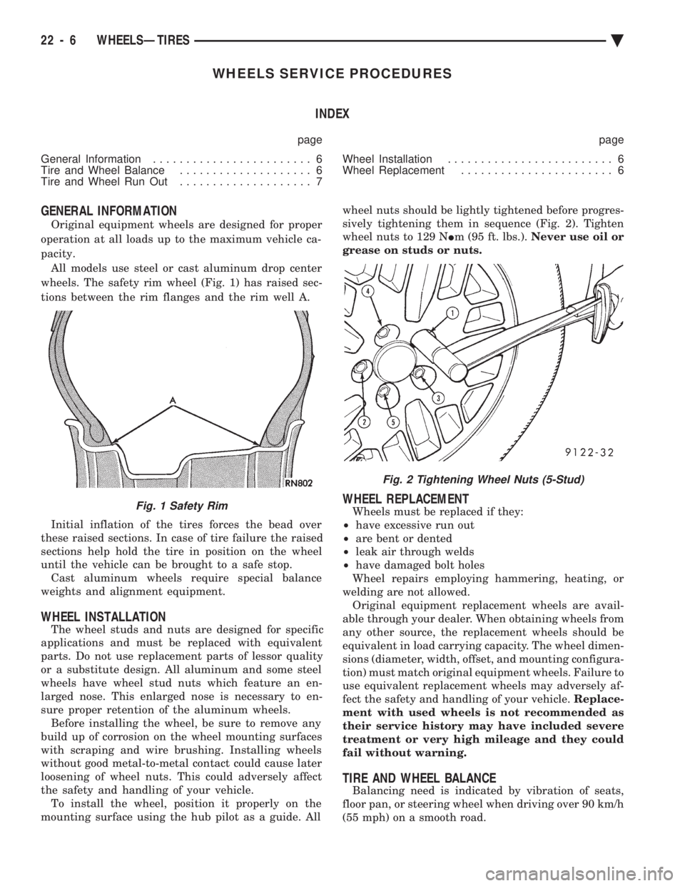
wheels. The safety rim wheel (Fig. 1) has raised sec-
tions between the rim flanges and the rim well A.
Initial inflation of the tires forces the bead over
these raised sections. In case of tire failure the raised
sections help hold the tire in position on the wheel
until the vehicle can be brought to a safe stop. Cast aluminum wheels require special balance
weights and alignment equipment.
WHEEL INSTALLATION
The wheel studs and nuts are designed for specific
applications and must be replaced with equivalent
parts. Do not use replacement parts of lessor quality
or a substitute design. All aluminum and some steel
wheels have wheel stud nuts which feature an en-
larged nose. This enlarged nose is necessary to en-
sure proper retention of the aluminum wheels. Before installing the wheel, be sure to remove any
build up of corrosion on the wheel mounting surfaces
with scraping and wire brushing. Installing wheels
without good metal-to-metal contact could cause later
loosening of wheel nuts. This could adversely affect
the safety and handling of your vehicle. To install the wheel, position it properly on the
mounting surface using the hub pilot as a guide. All wheel nuts should be lightly tightened before progres-
sively tightening them in sequence (Fig. 2). Tighten
wheel nuts to 129 N Im (95 ft. lbs.). Never use oil or
grease on studs or nuts.
WHEEL REPLACEMENT
Wheels must be replaced if they:
² have excessive run out
² are bent or dented
² leak air through welds
² have damaged bolt holes
Wheel repairs employing hammering, heating, or
welding are not allowed. Original equipment replacement wheels are avail-
able through your dealer. When obtaining wheels from
any other source, the replacement wheels should be
equivalent in load carrying capacity. The wheel dimen-
sions (diameter, width, offset, and mounting configura-
tion) must match original equipment wheels. Failure to
use equivalent replacement wheels may adversely af-
fect the safety and handling of your vehicle. Replace-
ment with used wheels is not recommended as
their service history may have included severe
treatment or very high mileage and they could
fail without warning.
TIRE AND WHEEL BALANCE
Balancing need is indicated by vibration of seats,
floor pan, or steering wheel when driving over 90 km/h
(55 mph) on a smooth road.
Fig. 1 Safety Rim
Fig. 2 Tightening Wheel Nuts (5-Stud)
22 - 6 WHEELSÐTIRES Ä
Page 2157 of 2438
BODY
CONTENTS
page page
AA-VEHICLE BODY COMPONENT SERVICE . . . 11
AC-VEHICLE BODY COMPONENT SERVICE . . . 37
AG-VEHICLE BODY COMPONENT SERVICE . . . 52
AJ-VEHICLE BODY COMPONENT SERVICE . . . 71
AJ/27-VEHICLE CONVERTIBLE BODYCOMPONENT SERVICE ................. 86
AP-VEHICLE BODY COMPONENT SERVICE . . . 97
AP/17-VEHICLE CONVERTIBLE BODY COMPONENT SERVICE ................. 117 AY-VEHICLE BODY COMPONENT SERVICE . . 133
BODY DIAGNOSTIC PROCEDURES .......... 2
GENERAL SERVICE INFORMATION .......... 1
PAINT ................................. 4
POWER SUNROOF ....................... 6
WINDSHIELD ........................... 9
GENERAL SERVICE INFORMATION
VEHICLE IDENTIFICATION
Throughout this group, references to the Chrysler
Corporation vehicle family identification code is used
when describing a procedure that is unique to that
vehicle. Refer to Introduction Group of this manual for
detailed information on vehicle identification. If a
procedure is common to all vehicles covered in this
manual, no reference will be made to a vehicle family
code.
SAFETY PRECAUTIONS AND WARNINGS
WARNING: WHEN SERVICING A VEHICLE EQUIPPED
WITH AIRBAG RESTRAINT SYSTEM, REVIEW ALL
PRECAUTIONS IN GROUP 8M, RESTRAINT SYS-
TEMS. PERSONAL INJURY CAN RESULT. EYE PROTECTION SHOULD BE USED WHEN SER-
VICING GLASS COMPONENTS. PERSONAL INJURY
CAN RESULT. USE A BREATHING FILTER WHEN SPRAYING
PAINT OR SOLVENTS IN A CONFINED AREA. PER-
SONAL INJURY CAN RESULT. AVOID PROLONGED SKIN CONTACT WITH PETRO-
LEUM OR ALCOHOL BASED CLEANING SOLVENTS.
PERSONAL INJURY CAN RESULT. DO NOT VENTURE UNDER A HOISTED VEHICLE
THAT IS NOT PROPERLY SUPPORTED ON SAFETY
STANDS. PERSONAL INJURY CAN RESULT.
CAUTION: When holes must be drilled or punched in
a inner body panel, verify depth of space to the outer
body panel, electrical wiring, or other components.
Damage to vehicle can result. Do not use abrasive chemicals or compounds on
painted surfaces. Damage to finish can result. Do not use harsh alkaline based cleaning solvents
on painted or upholstered surfaces. Damage to finish
or color can result. Do not hammer or pound on plastic trim panel
attaching fasteners when servicing interior trim. Plas-
tic panel can break.
Chrysler Corporation uses many different types of
push-in fasteners to secure the interior and exterior
trim to the body . Most of these fasteners can be reused
to assemble the trim during various repair procedures.
At times a push-in fastener cannot be removed without
damaging the fastener or the component it is holding.
If it is not possible to remove a fastener without
damaging a component or body, cut or brake the
fastener and use a new one when installing the com-
ponent. Never pry or pound on a plastic or press-board
trim component. Using a suitable fork-type prying
device, pry the fastener from the retaining hole behind
the component being removed. When installing, verify
that fastener is aligned with the retaining hole, by
hand, push directly on or over the fastener until it
seats. Apply a low force pull to the panel to verify that
it is secure. When it is necessary to remove components to service
another, it should not be necessary to apply excessive
force or bend a component to remove it. Before damag-
ing a component to be reused, verify there is no hidden
fasteners or captured edges holding the component in.
Often a fastener is hidden by carpeting nap or trim
plugs.
Ä BODY 23 - 1
Page 2167 of 2438
AA-VEHICLE BODY COMPONENT SERVICE INDEX
page page
A-Pillar and Roof Rail Mouldings ............. 25
B-Pillar Trim Panel ....................... 25
Body Side Moulding and Applique ............ 24
Cowl Cover ............................. 13
Cowl Panel Trim and Scuff Plates ............ 25
Door Opening Weatherstrips ................ 24
Floor Carpet ............................ 30
Front Center Console ..................... 29
Front Door and Hinge ..................... 15
Front Door Belt Moulding and Weatherstrip ..... 17
Front Door Glass ........................ 17
Front Door Glass Channel and Run Weatherstrip . 18
Front Door Glass Run Lower Channel ......... 18
Front Door Latch ......................... 16
Front Door Side View Mirror ................ 17
Front Door Silencer and Water Shield ......... 15
Front Door Trim Panel .................... 14
Front Door Window Regulator/Manual ......... 18
Front Door Window Regulator/Power .......... 19
Front End Splash Shields .................. 13
Front Fender ............................ 14
Front Power Door Lock Actuator ............. 19
Front Seat Belts ......................... 27
Front Seats ............................. 28
Fuel Fill Door ........................... 36
Grille .................................. 11
Head Lining ............................. 30
Hood and Hinges ........................ 11
Hood Latch and Release Cable .............. 12
Outside Front Door Latch Release Handle ..... 16
Outside Rear Door Latch Release Handle ...... 21 Overhead Console
........................ 30
Quarter Extension Trim Panel ............... 27
Quarter Trim Panel ....................... 27
Rear Deck Filler Panel .................... 31
Rear Door and Hinge ..................... 20
Rear Door Belt Moulding and Weatherstrip ..... 22
Rear Door Glass ......................... 22
Rear Door Glass Run Weatherstrip ........... 22
Rear Door Glass Stationary Glass Module ..... 23
Rear Door Latch ......................... 21
Rear Door Silencer and Water Shield ......... 20
Rear Door Trim Panel ..................... 20
Rear Door Window Regulator/Manual ......... 23
Rear Door Window Regulator/Power .......... 23
Rear Power Door Lock Actuator ............. 22
Rear Seat Belts .......................... 28
Rear Seats ............................. 28
Rear Shelf Trim Panel ..................... 27
Rear Window Glass ...................... 32
Sun Roof Air Deflector .................... 31
Sun Roof Drain Tubes .................... 31
Sun Roof Weatherstrip .................... 31
Trunk Lid .............................. 33
Trunk Lid Hinge ......................... 34
Trunk Lid Latch .......................... 34
Trunk Lid Lock .......................... 34
Trunk Lid Luggage Rack ................... 35
Trunk Lid Torsion Bar ..................... 34
Trunk Lining ............................ 35
Trunk Opening Weatherstrip ................ 35
Vinyl Roof Bonnet ........................ 31
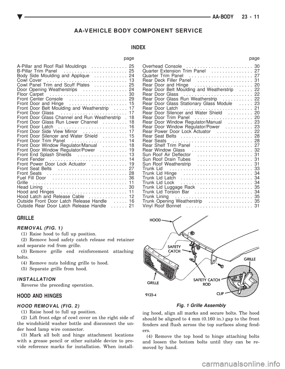
GRILLE
REMOVAL (FIG. 1)
(1) Raise hood to full up position.
(2) Remove hood safety catch release rod retainer
and separate rod from grille. (3) Remove grille end reinforcement attaching
bolts. (4) Remove nuts holding grille to hood.
(5) Separate grille from hood.
INSTALLATION
Reverse the preceding operation.
HOOD AND HINGES
HOOD REMOVAL (FIG. 2)
(1) Raise hood to full up position.
(2) Lift front edge of cowl cover on the right side of
the windshield washer bottle and disconnect the un-
der hood lamp wire connector. (3) Mark all bolt and hinge attachment locations
with a grease pencil or other suitable device to pro-
vide reference marks for installation. When install- ing hood, align all marks and secure bolts. The hood
should be aligned to 4 mm (0.160 in.) gap to the front
fenders and flush across the top surfaces along fend-
ers. (4) Remove the top hood to hinge attaching bolts
and loosen the bottom bolts until they can be re-
moved by hand.
Fig. 1 Grille Assembly
Ä AA-BODY 23 - 11
Page 2174 of 2438
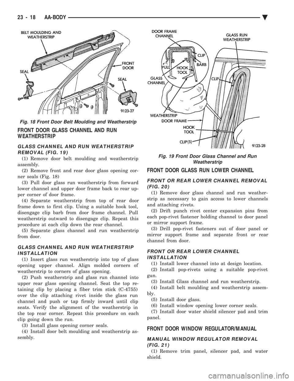
FRONT DOOR GLASS CHANNEL AND RUN
WEATHERSTRIP
GLASS CHANNEL AND RUN WEATHERSTRIP
REMOVAL (FIG. 19)
(1) Remove door belt moulding and weatherstrip
assembly. (2) Remove front and rear door glass opening cor-
ner seals (Fig. 18) (3) Pull door glass run weatherstrip from forward
lower channel and upper door frame back to rear up-
per corner of door frame. (4) Separate weatherstrip from top of rear door
frame down to first clip. Using a suitable hook tool,
disengage clip barb from door frame channel. Pull
weatherstrip outward to disengage clip. Repeat this
procedure at each clip down the rear channel. (5) Separate glass channel and run weatherstrip
from door.
GLASS CHANNEL AND RUN WEATHERSTRIP INSTALLATION
(1) Insert glass run weatherstrip into top of glass
opening upper channel. Align molded corners of
weatherstrip to corners of glass opening. (2) Push weatherstrip and glass run channel into
upper rear glass opening channel. Seat the top re-
taining clip by placing a fiber trim stick (C-4755)
over the clip attaching rivet inside the glass run
channel and push or tap firmly inward until clip
seats. Verify the alignment of the weatherstrip in
the top rear corner. Repeat this procedure on each
clip going down the run. (3) Install glass opening corner seals.
(4) Install door belt moulding and weatherstrip as-
sembly.
FRONT DOOR GLASS RUN LOWER CHANNEL
FRONT OR REAR LOWER CHANNEL REMOVAL (FIG. 20)
(1) Remove door glass channel and run weather-
strip as necessary to gain access to lower channels
and attaching rivets. (2) Drift punch rivet center expansion pins from
each pop-rivet fastener holding channel to door panel
or mirror support frame. (3) Drill pop-rivet fasteners out of door panel or
mirror support frame and separate front or rear
channel from door.
FRONT OR REAR LOWER CHANNEL INSTALLATION
(1) Install lower channel into at design location.
(2) Install pop-rivets using a suitable pop-rivet
gun. (3) Install Glass channel and run weatherstrip.
(4) Install belt moulding and weatherstrip assem-
bly. (5) Install door glass.
(6) Install window opening lower corner seals.
(7) Install door water shield silencer pad and trim
panel.
FRONT DOOR WINDOW REGULATOR/MANUAL
MANUAL WINDOW REGULATOR REMOVAL (FIG. 21)
(1) Remove trim panel, silencer pad, and water
shield.
Fig. 18 Front Door Belt Moulding and Weatherstrip
Fig. 19 Front Door Glass Channel and Run Weatherstrip
23 - 18 AA-BODY Ä
Page 2184 of 2438
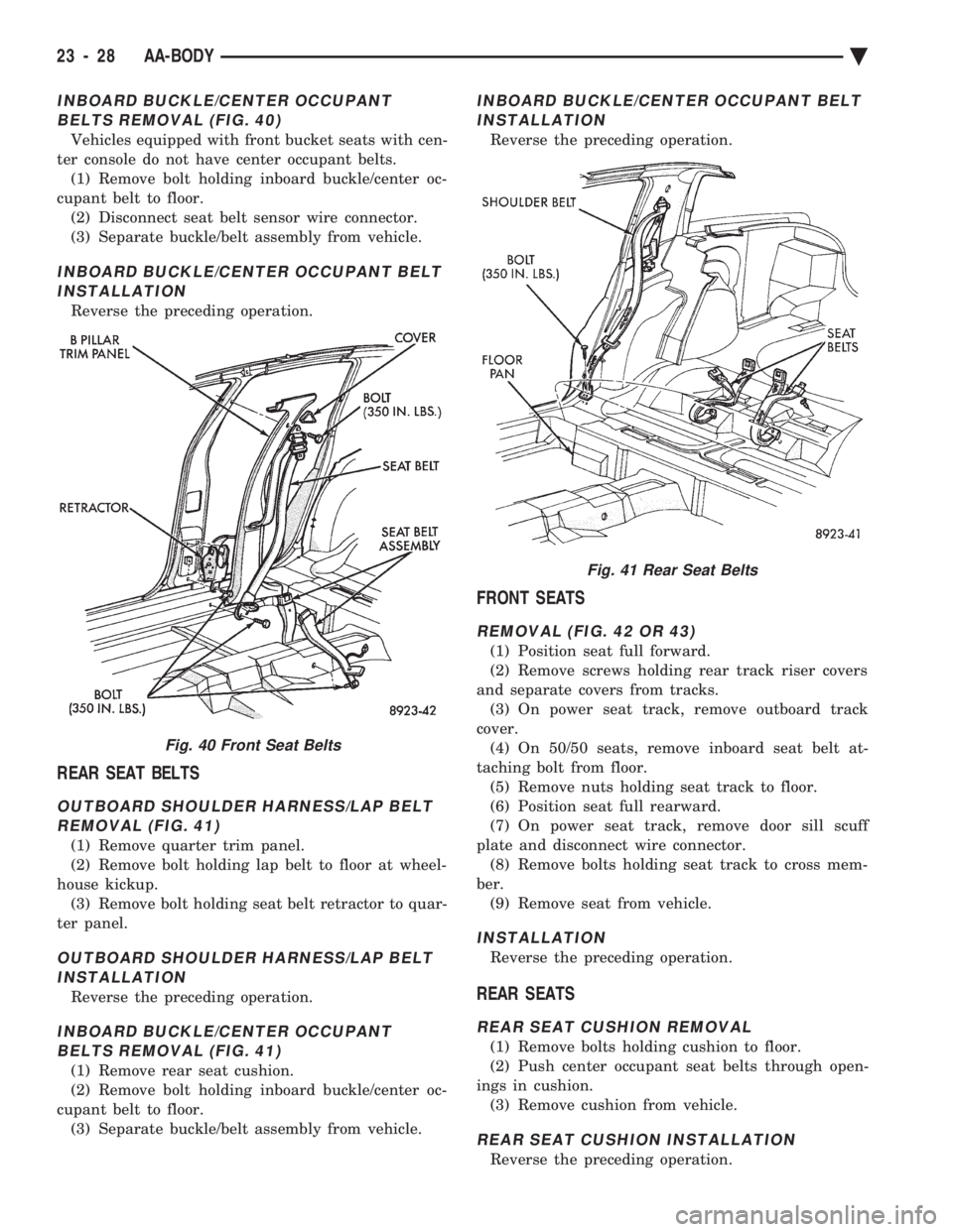
INBOARD BUCKLE/CENTER OCCUPANT BELTS REMOVAL (FIG. 40)
Vehicles equipped with front bucket seats with cen-
ter console do not have center occupant belts. (1) Remove bolt holding inboard buckle/center oc-
cupant belt to floor. (2) Disconnect seat belt sensor wire connector.
(3) Separate buckle/belt assembly from vehicle.
INBOARD BUCKLE/CENTER OCCUPANT BELT INSTALLATION
Reverse the preceding operation.
REAR SEAT BELTS
OUTBOARD SHOULDER HARNESS/LAP BELTREMOVAL (FIG. 41)
(1) Remove quarter trim panel.
(2) Remove bolt holding lap belt to floor at wheel-
house kickup. (3) Remove bolt holding seat belt retractor to quar-
ter panel.
OUTBOARD SHOULDER HARNESS/LAP BELT INSTALLATION
Reverse the preceding operation.
INBOARD BUCKLE/CENTER OCCUPANTBELTS REMOVAL (FIG. 41)
(1) Remove rear seat cushion.
(2) Remove bolt holding inboard buckle/center oc-
cupant belt to floor. (3) Separate buckle/belt assembly from vehicle.
INBOARD BUCKLE/CENTER OCCUPANT BELTINSTALLATION
Reverse the preceding operation.
FRONT SEATS
REMOVAL (FIG. 42 OR 43)
(1) Position seat full forward.
(2) Remove screws holding rear track riser covers
and separate covers from tracks. (3) On power seat track, remove outboard track
cover. (4) On 50/50 seats, remove inboard seat belt at-
taching bolt from floor. (5) Remove nuts holding seat track to floor.
(6) Position seat full rearward.
(7) On power seat track, remove door sill scuff
plate and disconnect wire connector. (8) Remove bolts holding seat track to cross mem-
ber. (9) Remove seat from vehicle.
INSTALLATION
Reverse the preceding operation.
REAR SEATS
REAR SEAT CUSHION REMOVAL
(1) Remove bolts holding cushion to floor.
(2) Push center occupant seat belts through open-
ings in cushion. (3) Remove cushion from vehicle.
REAR SEAT CUSHION INSTALLATION
Reverse the preceding operation.
Fig. 40 Front Seat Belts
Fig. 41 Rear Seat Belts
23 - 28 AA-BODY Ä