brakes CHEVROLET DYNASTY 1993 Service Manual
[x] Cancel search | Manufacturer: CHEVROLET, Model Year: 1993, Model line: DYNASTY, Model: CHEVROLET DYNASTY 1993Pages: 2438, PDF Size: 74.98 MB
Page 18 of 2438
GROUP TAB LOCATOR
Introduction
0Lubrication and Maintenance
2Suspension/Driveshafts
5Brakes
6Manual Transaxle Clutch
7Cooling System
9Engine
11Exhaust System and Intake Manifold
13Frame and Bumpers
19Steering
21Transaxle
22Wheels/Tires
23Body
24Heating/Air Conditioning
Component and System Index
Service Manual Comment Forms (Rear of Manual)
Page 26 of 2438
GROUP TAB LOCATOR
5Brakes
8WWiring Diagrams
Component and System Index
Service Manual Comment Forms (Rear of Manual)
Page 31 of 2438
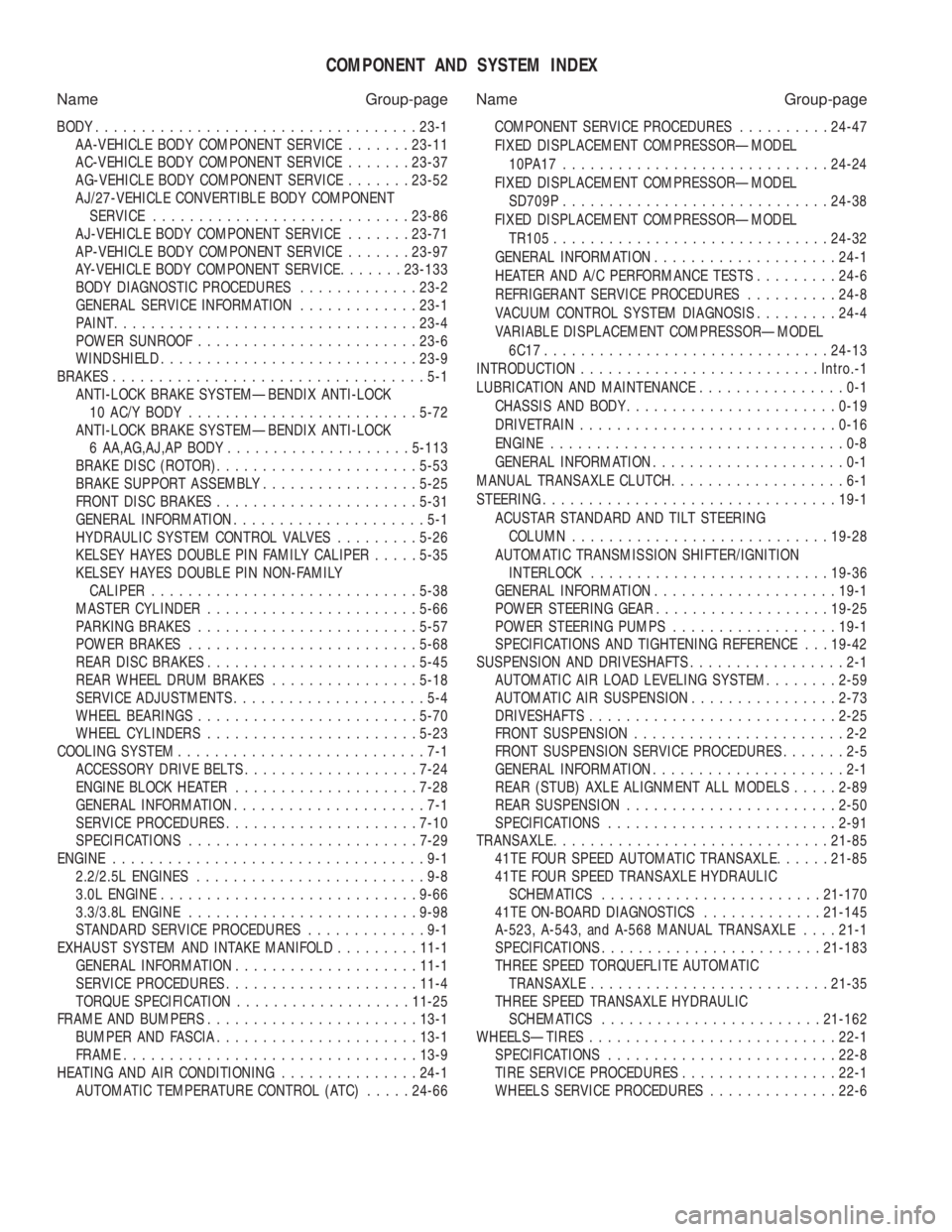
COMPONENT AND SYSTEM INDEX
Name Group-page Name Group-page
BODY ................................... 23-1
AA-VEHICLE BODY COMPONENT SERVICE .......23-11
AC-VEHICLE BODY COMPONENT SERVICE .......23-37
AG-VEHICLE BODY COMPONENT SERVICE .......23-52
AJ/27-VEHICLE CONVERTIBLE BODY COMPONENT SERVICE ............................ 23-86
AJ-VEHICLE BODY COMPONENT SERVICE .......23-71
AP-VEHICLE BODY COMPONENT SERVICE .......23-97
AY-VEHICLE BODY COMPONENT SERVICE .......23-133
BODY DIAGNOSTIC PROCEDURES .............23-2
GENERAL SERVICE INFORMATION .............23-1
PAINT ................................. 23-4
POWER SUNROOF ........................ 23-6
WINDSHIELD ............................ 23-9
BRAKES ..................................5-1
ANTI-LOCK BRAKE SYSTEMÐBENDIX ANTI-LOCK 10 AC/Y BODY ......................... 5-72
ANTI-LOCK BRAKE SYSTEMÐBENDIX ANTI-LOCK 6 AA,AG,AJ,AP BODY .................... 5-113
BRAKE DISC (ROTOR) ...................... 5-53
BRAKE SUPPORT ASSEMBLY .................5-25
FRONT DISC BRAKES ...................... 5-31
GENERAL INFORMATION .....................5-1
HYDRAULIC SYSTEM CONTROL VALVES .........5-26
KELSEY HAYES DOUBLE PIN FAMILY CALIPER .....5-35
KELSEY HAYES DOUBLE PIN NON-FAMILY CALIPER ............................. 5-38
MASTER CYLINDER ....................... 5-66
PARKING BRAKES ........................ 5-57
POWER BRAKES ......................... 5-68
REAR DISC BRAKES ....................... 5-45
REAR WHEEL DRUM BRAKES ................5-18
SERVICE ADJUSTMENTS .....................5-4
WHEEL BEARINGS ........................ 5-70
WHEEL CYLINDERS ....................... 5-23
COOLING SYSTEM ...........................7-1
ACCESSORY DRIVE BELTS ................... 7-24
ENGINE BLOCK HEATER .................... 7-28
GENERAL INFORMATION .....................7-1
SERVICE PROCEDURES ..................... 7-10
SPECIFICATIONS ......................... 7-29
ENGINE ..................................9-1
2.2/2.5L ENGINES .........................9-8
3.0L ENGINE ............................ 9-66
3.3/3.8L ENGINE ......................... 9-98
STANDARD SERVICE PROCEDURES .............9-1
EXHAUST SYSTEM AND INTAKE MANIFOLD .........11-1
GENERAL INFORMATION .................... 11-1
SERVICE PROCEDURES ..................... 11-4
TORQUE SPECIFICATION ................... 11-25
FRAME AND BUMPERS ....................... 13-1
BUMPER AND FASCIA ...................... 13-1
FRAME ................................ 13-9
HEATING AND AIR CONDITIONING ...............24-1
AUTOMATIC TEMPERATURE CONTROL (ATC) .....24-66 COMPONENT SERVICE PROCEDURES
..........24-47
FIXED DISPLACEMENT COMPRESSORÐMODEL 10PA17............................. 24-24
FIXED DISPLACEMENT COMPRESSORÐMODEL SD709P ............................. 24-38
FIXED DISPLACEMENT COMPRESSORÐMODEL TR105 .............................. 24-32
GENERAL INFORMATION .................... 24-1
HEATER AND A/C PERFORMANCE TESTS .........24-6
REFRIGERANT SERVICE PROCEDURES ..........24-8
VACUUM CONTROL SYSTEM DIAGNOSIS .........24-4
VARIABLE DISPLACEMENT COMPRESSORÐMODEL 6C17 ............................... 24-13
INTRODUCTION .......................... Intro.-1
LUBRICATION AND MAINTENANCE ................0-1
CHASSIS AND BODY ....................... 0-19
DRIVETRAIN ............................ 0-16
ENGINE ................................0-8
GENERAL INFORMATION .....................0-1
MANUAL TRANSAXLE CLUTCH ...................6-1
STEERING ................................ 19-1
ACUSTAR STANDARD AND TILT STEERING COLUMN ............................ 19-28
AUTOMATIC TRANSMISSION SHIFTER/IGNITION INTERLOCK .......................... 19-36
GENERAL INFORMATION .................... 19-1
POWER STEERING GEAR ................... 19-25
POWER STEERING PUMPS ..................19-1
SPECIFICATIONS AND TIGHTENING REFERENCE . . . 19-42
SUSPENSION AND DRIVESHAFTS .................2-1
AUTOMATIC AIR LOAD LEVELING SYSTEM ........2-59
AUTOMATIC AIR SUSPENSION ................2-73
DRIVESHAFTS ........................... 2-25
FRONT SUSPENSION .......................2-2
FRONT SUSPENSION SERVICE PROCEDURES .......2-5
GENERAL INFORMATION .....................2-1
REAR (STUB) AXLE ALIGNMENT ALL MODELS .....2-89
REAR SUSPENSION ....................... 2-50
SPECIFICATIONS ......................... 2-91
TRANSAXLE .............................. 21-85
41TE FOUR SPEED AUTOMATIC TRANSAXLE ......21-85
41TE FOUR SPEED TRANSAXLE HYDRAULIC SCHEMATICS ........................ 21-170
41TE ON-BOARD DIAGNOSTICS .............21-145
A-523, A-543, and A-568 MANUAL TRANSAXLE ....21-1
SPECIFICATIONS ........................ 21-183
THREE SPEED TORQUEFLITE AUTOMATIC TRANSAXLE .......................... 21-35
THREE SPEED TRANSAXLE HYDRAULIC SCHEMATICS ........................ 21-162
WHEELSÐTIRES ........................... 22-1
SPECIFICATIONS ......................... 22-8
TIRE SERVICE PROCEDURES .................22-1
WHEELS SERVICE PROCEDURES ..............22-6
Page 35 of 2438
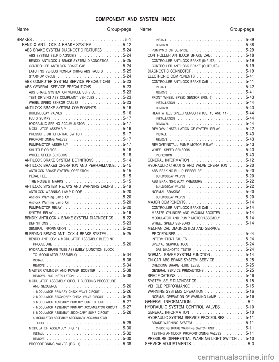
COMPONENT AND SYSTEM INDEX
Name Group-page Name Group-page
BRAKES ..................................5-1
BENDIX ANTILOCK 4 BRAKE SYSTEM ...........5-12
ABS BRAKE SYSTEM DIAGNOSTIC FEATURES.......5-24
ABS SYSTEM SELF DIAGNOSIS................ 5-24
BENDIX ANTILOCK 4 BRAKE SYSTEM DIAGNOSTICS....5-25
CONTROLLER ANTILOCK BRAKE CAB............. 5-24
LATCHING VERSUS NON-LATCHING ABS FAULTS.......5-25
START-UP CYCLE........................ 5-24
ABS COMPUTER SYSTEM SERVICE PRECAUTIONS....5-23
ABS GENERAL SERVICE PRECAUTIONS........... 5-23
ABS BRAKE SYSTEM ON VEHICLE SERVICE.........5-23
TEST DRIVING ABS COMPLAINT VEHICLES.......... 5-23
WHEEL SPEED SENSOR CABLES............... 5-23
ANTILOCK BRAKE SYSTEM COMPONENTS..........5-16
BUILD/DECAY VALVES..................... 5-16
FLUID SUMPS.......................... 5-17
HYDRAULIC SPRING ACCUMULATOR.............5-17
MODULATOR ASSEMBLY.................... 5-16
PRESSURE DIFFERENTIAL SWITCH..............5-17
PROPORTIONING VALVES................... 5-17
PUMP/MOTOR ASSEMBLY...................5-17
SHUTTLE ORIFICE........................ 5-16
WHEEL SPEED SENSORS....................5-18
ANTILOCK BRAKE SYSTEM DEFINITIONS..........5-14
ANTILOCK BRAKES OPERATION AND PERFORMANCE. . . 5-15
ANTILOCK BRAKE SYSTEM OPERATION............ 5-15
PEDAL FEEL........................... 5-15
TIRE NOISE & MARKS.....................5-15
ANTILOCK SYSTEM RELAYS AND WARNING LAMPS. . . 5-19
ANTILOCK WARNING LAMP DIODE..............5-20
Antilock Warning Lamp Off................... 5-20
Antilock Warning Lamp On...................5-20
PUMP/MOTOR RELAY...................... 5-20
SYSTEM RELAY......................... 5-19
BENDIX ANTILOCK 4 BRAKE SYSTEM DIAGNOSTICS. . . 5-22
DEFINITIONS........................... 5-23
GENERAL INFORMATION....................5-22
BLEEDING BENDIX ANTILOCK 4 BRAKE SYSTEM......5-25
BENDIX ANTILOCK 4 MODULATOR ASSEMBLY BLEEDING
PROCEDURE
......................... 5-26
HYDRAULIC BRAKE TUBE ASSEMBLY (JUNCTION BLOCK
TO MODULATOR ASSEMBLY)
................ 5-34
INSTALL............................ 5-36
REMOVE............................5-34
MASTER CYLINDER AND POWER BOOSTER.........5-38
REMOVAL AND INSTALLATION................. 5-38
MODULATOR ASSEMBLY CIRCUIT BLEEDING PROCEDURE
AND SEQUENCE
....................... 5-26
1 MODULATOR PRIMARY CHECK VALVE CIRCUIT........5-26
2 MODULATOR SECONDARY CHECK VALVE CIRCUIT......5-26
3 MODULATOR ASSEMBLY PRIMARY SUMP CIRCUIT......5-27
4 MODULATOR ASSEMBLY PRIMARY ACCUMULATOR CIRCUIT. 5-27
5 MODULATOR ASSEMBLY SECONDARY SUMP CIRCUIT....5-28
6 MODULATOR ASSEMBLY SECONDARY ACCUMULATOR
CIRCUIT
........................... 5-29
MODULATOR ASSEMBLY (FIG. 1)...............5-30
INSTALL............................ 5-32
REMOVE............................5-30
PROPORTIONING VALVES (FIG. 1)...............5-38
INSTALL............................ 5-39
REMOVAL...........................5-38
PUMP/MOTOR SERVICE....................5-29
CONTROLLER ANTILOCK BRAKE CAB.............5-18
CONTROLLER ANTILOCK BRAKE (INPUTS)..........5-19
CONTROLLER ANTILOCK BRAKE (OUTPUTS).........5-19
DIAGNOSTIC CONNECTOR.................... 5-19
ELECTRONIC COMPONENTS..................5-41
CONTROLLER ANTILOCK BRAKE CAB.............5-41
INSTALL............................ 5-42
REMOVE............................5-41
FRONT WHEEL SPEED SENSOR (FIG. 9)...........5-43
INSTALLATION......................... 5-44
REMOVAL........................... 5-43
REAR WHEEL SPEED SENSOR (FIGS. 10 AND 11)......5-44
INSTALLATION......................... 5-44
REMOVAL........................... 5-44
REMOVAL/INSTALLATION OF SYSTEM RELAY.........5-42
INSTALL............................ 5-43
REMOVE............................5-43
REMOVE/INSTALL PUMP MOTOR RELAY...........5-43
WHEEL SPEED SENSORS.................... 5-43
INSPECTION.......................... 5-43
GENERAL INFORMATION....................5-12
HYDRAULIC CIRCUITS AND VALVE OPERATION......5-20
ABS BRAKING-BUILD PRESSURE............... 5-20
BUILD/DECAY VALVES..................... 5-20
ABS BRAKING-DECAY PRESSURE...............5-22
BUILD/DECAY VALVES..................... 5-22
NORMAL BRAKING....................... 5-20
BUILD/DECAY VALVES.....................5-20
MAJOR COMPONENTS...................... 5-14
CONTROLLER ANTILOCK BRAKE CAB.............5-14
MASTER CYLINDER AND VACUUM BOOSTER.........5-14
MODULATOR AND PUMP MOTOR/ASSEMBLY.........5-14
WHEEL SPEED SENSORS.................... 5-14
MECHANICAL DIAGNOSTICS AND SERVICE
PROCEDURES
.......................... 5-24
INTERMITTENT FAULTS.....................5-24
SPECIAL SERVICE TOOL....................5-24
DRB DIAGNOSTIC TESTER...................5-24
NORMAL BRAKE SYSTEM FUNCTION.............5-14
ON-CAR ABS BRAKE SYSTEM SERVICE...........5-25
CHECKING BRAKE FLUID LEVEL................ 5-25
GENERAL SERVICE PRECAUTIONS...............5-25
SPECIFICATIONS......................... 5-46
SYSTEM SELF-DIAGNOSTICS..................5-15
VEHICLE PERFORMANCE.................... 5-15
WARNING SYSTEMS OPERATION...............5-16
NORMAL OPERATION OF WARNING LAMP..........5-16
GENERAL INFORMATION .....................5-1
HYDRAULIC SYSTEM CONTROL VALVES .........5-10
GENERAL INFORMATION.................... 5-10
HYDRAULIC SYSTEM SERVICE PROCEDURES........5-11
BRAKE WARNING SYSTEM................... 5-11
CHECKING BRAKE WARNING SWITCH UNIT...........5-11
TESTING ANTILOCK PROPORTIONING VALVES........5-11
PRESSURE DIFFERENTIAL WARNING LIGHT SWITCH. . . 5-10
SERVICE ADJUSTMENTS .....................5-3
Page 52 of 2438
DRIVETRAIN INDEX
page page
Automatic Transaxle ...................... 16
Automatic Transaxle Floor Shift .............. 16
Clutch and Gearshift Linkage ............... 16
Drive Shaft Cv and Tripod Joint Boots ........ 17 Front Wheel Bearings
..................... 17
Manual Transaxle ........................ 16
Tires .................................. 17
CLUTCH AND GEARSHIFT LINKAGE
If the clutch or gearshift begins to operate with dif-
ficulty, squeak or grunt, the cables and linkage
should be lubricated before service replacement is
performed. For proper lubrication and service proce-
dures refer to Group 6, Clutch, or Group 21, Manual
Transaxle.
MANUAL TRANSAXLE
The manual transaxle should be inspected for oil
leaks and proper oil level when other under vehicle
service is performed. To inspect the transaxle oil
level, position the vehicle on a level surface. Remove
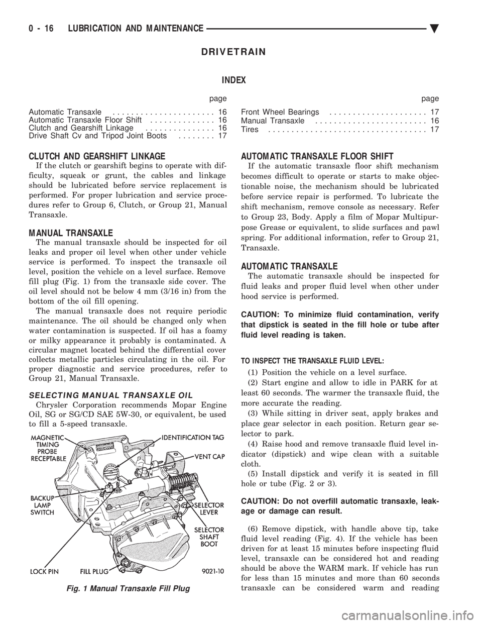
fill plug (Fig. 1) from the transaxle side cover. The
oil level should not be below 4 mm (3/16 in) from the
bottom of the oil fill opening. The manual transaxle does not require periodic
maintenance. The oil should be changed only when
water contamination is suspected. If oil has a foamy
or milky appearance it probably is contaminated. A
circular magnet located behind the differential cover
collects metallic particles circulating in the oil. For
proper diagnostic and service procedures, refer to
Group 21, Manual Transaxle.
SELECTING MANUAL TRANSAXLE OIL
Chrysler Corporation recommends Mopar Engine
Oil, SG or SG/CD SAE 5W-30, or equivalent, be used
to fill a 5-speed transaxle.
AUTOMATIC TRANSAXLE FLOOR SHIFT
If the automatic transaxle floor shift mechanism
becomes difficult to operate or starts to make objec-
tionable noise, the mechanism should be lubricated
before service repair is performed. To lubricate the
shift mechanism, remove console as necessary. Refer
to Group 23, Body. Apply a film of Mopar Multipur-
pose Grease or equivalent, to slide surfaces and pawl
spring. For additional information, refer to Group 21,
Transaxle.
AUTOMATIC TRANSAXLE
The automatic transaxle should be inspected for
fluid leaks and proper fluid level when other under
hood service is performed.
CAUTION: To minimize fluid contamination, verify
that dipstick is seated in the fill hole or tube after
fluid level reading is taken.
TO INSPECT THE TRANSAXLE FLUID LEVEL: (1) Position the vehicle on a level surface.
(2) Start engine and allow to idle in PARK for at
least 60 seconds. The warmer the transaxle fluid, the
more accurate the reading. (3) While sitting in driver seat, apply brakes and
place gear selector in each position. Return gear se-
lector to park. (4) Raise hood and remove transaxle fluid level in-
dicator (dipstick) and wipe clean with a suitable
cloth. (5) Install dipstick and verify it is seated in fill
hole or tube (Fig. 2 or 3).
CAUTION: Do not overfill automatic transaxle, leak-
age or damage can result.
(6) Remove dipstick, with handle above tip, take
fluid level reading (Fig. 4). If the vehicle has been
driven for at least 15 minutes before inspecting fluid
level, transaxle can be considered hot and reading
should be above the WARM mark. If vehicle has run
for less than 15 minutes and more than 60 seconds
transaxle can be considered warm and reading
Fig. 1 Manual Transaxle Fill Plug
0 - 16 LUBRICATION AND MAINTENANCE Ä
Page 55 of 2438
CHASSIS AND BODY INDEX
page page
Body Lubrication ......................... 22
Brakes ................................ 21
Headlamps ............................. 22
Lower Ball Joints ......................... 19 Power Steering
.......................... 19
Rear Wheel Bearings ..................... 20
Steering Linkage ......................... 19
STEERING LINKAGE
INSPECTION
The steering linkage and steering gear should be in-
spected for wear, leaks or damage when other under ve-
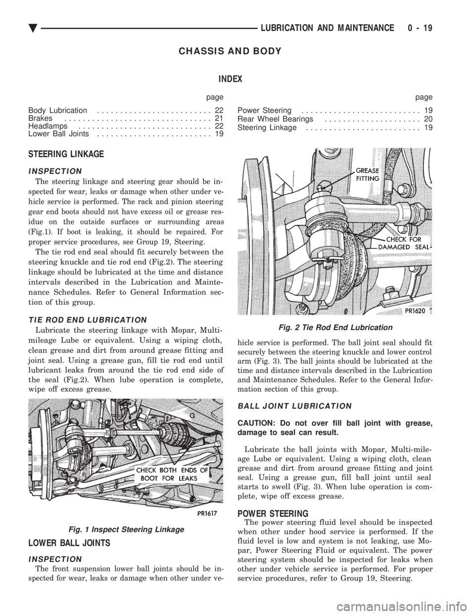
hicle service is performed. The rack and pinion steering
gear end boots should not have excess oil or grease res-
idue on the outside surfaces or surrounding areas
(Fig.1). If boot is leaking, it should be repaired. For
proper service procedures, see Group 19, Steering.
The tie rod end seal should fit securely between the
steering knuckle and tie rod end (Fig.2). The steering
linkage should be lubricated at the time and distance
intervals described in the Lubrication and Mainte-
nance Schedules. Refer to General Information sec-
tion of this group.
TIE ROD END LUBRICATION
Lubricate the steering linkage with Mopar, Multi-
mileage Lube or equivalent. Using a wiping cloth,
clean grease and dirt from around grease fitting and
joint seal. Using a grease gun, fill tie rod end until
lubricant leaks from around the tie rod end side of
the seal (Fig.2). When lube operation is complete,
wipe off excess grease.
LOWER BALL JOINTS
INSPECTION
The front suspension lower ball joints should be in-
spected for wear, leaks or damage when other under ve- hicle service is performed. The ball joint seal should fit
securely between the steering knuckle and lower control
arm (Fig. 3). The ball joints should be lubricated at the
time and distance intervals described in the Lubrication
and Maintenance Schedules. Refer to the General Infor-
mation section of this group.
BALL JOINT LUBRICATION
CAUTION: Do not over fill ball joint with grease,
damage to seal can result.
Lubricate the ball joints with Mopar, Multi-mile-
age Lube or equivalent. Using a wiping cloth, clean
grease and dirt from around grease fitting and joint
seal. Using a grease gun, fill ball joint until seal
starts to swell (Fig. 3). When lube operation is com-
plete, wipe off excess grease.
POWER STEERING
The power steering fluid level should be inspected
when other under hood service is performed. If the
fluid level is low and system is not leaking, use Mo-
par, Power Steering Fluid or equivalent. The power
steering system should be inspected for leaks when
other under vehicle service is performed. For proper
service procedures, refer to Group 19, Steering.Fig. 1 Inspect Steering Linkage
Fig. 2 Tie Rod End Lubrication
Ä LUBRICATION AND MAINTENANCE 0 - 19
Page 57 of 2438
flakes are visible in the used lubricant or the bearing
rollers and race cup is discolored, the bearing and
race cup should be replaced. For proper service pro-
cedures, see Group 5, Brakes. Replace the inner seal
whenever the wheel bearings are serviced.
REAR WHEEL BEARING LUBRICATION
CAUTION: Combining two types of lubricant can
cause bearing failure. Wash used or new bearings
with a suitable solvent and blot dry with a lint free
cloth before packing with new lubricant.
WARNING: DO NOT ALLOW BEARING TO SPIN AT
HIGH RPM WHEN USING COMPRESSED AIR TO
BLOW CLEANING SOLVENT FROM BEARING.
BEARING CAGE CAN EXPLODE, CAUSING PER-
SONAL INJURY.
TO LUBRICATE REAR WHEEL BEARINGS:
(1) Hoist rear wheels off the ground and support ve-
hicle on safety stands. Refer to Hoisting Recommenda-
tions in the General Information section of this group.
(2) Remove rear wheels.
(3) Remove brake caliper on vehicles with rear disc
brakes. For proper procedure, see Group 5, Brakes. (4) Remove rear wheel hub (drum) assembly and
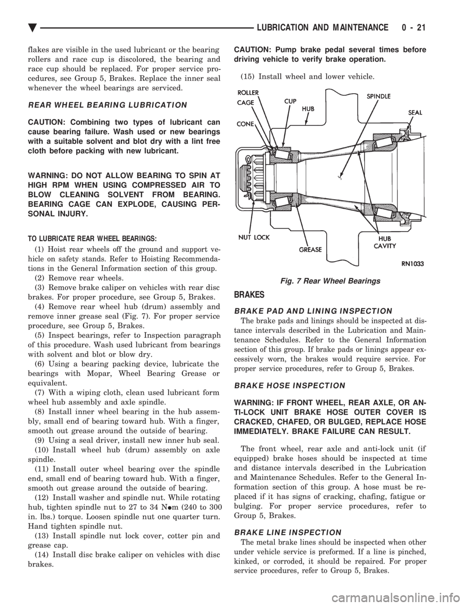
remove inner grease seal (Fig. 7). For proper service
procedure, see Group 5, Brakes. (5) Inspect bearings, refer to Inspection paragraph
of this procedure. Wash used lubricant from bearings
with solvent and blot or blow dry. (6) Using a bearing packing device, lubricate the
bearings with Mopar, Wheel Bearing Grease or
equivalent. (7) With a wiping cloth, clean used lubricant form
wheel hub assembly and axle spindle. (8) Install inner wheel bearing in the hub assem-
bly, small end of bearing toward hub. With a finger,
smooth out grease around the outside of bearing. (9) Using a seal driver, install new inner hub seal.
(10) Install wheel hub (drum) assembly on axle
spindle. (11) Install outer wheel bearing over the spindle
end, small end of bearing toward hub. With a finger,
smooth out grease around the outside of bearing. (12) Install washer and spindle nut. While rotating
hub, tighten spindle nut to 27 to 34 N Im (240 to 300
in. lbs.) torque. Loosen spindle nut one quarter turn.
Hand tighten spindle nut. (13) Install spindle nut lock cover, cotter pin and
grease cap. (14) Install disc brake caliper on vehicles with disc
brakes. CAUTION: Pump brake pedal several times before
driving vehicle to verify brake operation.
(15) Install wheel and lower vehicle.
BRAKES
BRAKE PAD AND LINING INSPECTION
The brake pads and linings should be inspected at dis-
tance intervals described in the Lubrication and Main-
tenance Schedules. Refer to the General Information
section of this group. If brake pads or linings appear ex-
cessively worn, the brakes would require service. For
proper service procedures, refer to Group 5, Brakes.
BRAKE HOSE INSPECTION
WARNING: IF FRONT WHEEL, REAR AXLE, OR AN-
TI-LOCK UNIT BRAKE HOSE OUTER COVER IS
CRACKED, CHAFED, OR BULGED, REPLACE HOSE
IMMEDIATELY. BRAKE FAILURE CAN RESULT.
The front wheel, rear axle and anti-lock unit (if
equipped) brake hoses should be inspected at time
and distance intervals described in the Lubrication
and Maintenance Schedules. Refer to the General In-
formation section of this group. A hose must be re-
placed if it has signs of cracking, chafing, fatigue or
bulging. For proper service procedures, refer to
Group 5, Brakes.
BRAKE LINE INSPECTION
The metal brake lines should be inspected when other
under vehicle service is preformed. If a line is pinched,
kinked, or corroded, it should be repaired. For proper
service procedures, refer to Group 5, Brakes.
Fig. 7 Rear Wheel Bearings
Ä LUBRICATION AND MAINTENANCE 0 - 21
Page 58 of 2438
BRAKE RESERVOIR LEVEL INSPECTION
WARNING: DO NOT ALLOW PETROLEUM OR WATER
BASE LIQUIDS TO CONTAMINATE BRAKE FLUID,
SEAL DAMAGE AND BRAKE FAILURE CAN RESULT.
RELIEVE PRESSURE IN ANTI-LOCK BRAKE SYS-
TEM BEFORE ADDING BRAKE FLUID TO RESER-
VOIR. IF NOT, BRAKE FLUID COULD DISCHARGED
FROM THE RESERVOIR POSSIBLY CAUSING PER-
SONAL INJURY.
The brake reservoir level should be inspected when
other under hood service is performed. It is normal
for the reservoir level to drop as disc brake pads
wear. When fluid must be added, use Mopar, Brake
Fluid or equivalent. Use only brake fluid conforming
to DOT 3, Federal, Department of Transportation
specification. To avoid brake fluid contamination, use
fluid from a properly sealed container. On vehicles with anti-lock brakes, depressurize the
system before inspecting fluid level. Turn OFF the
ignition and remove the key. Pump the brake pedal
at least 50 times to relieve the pressure in the sys-
tem.
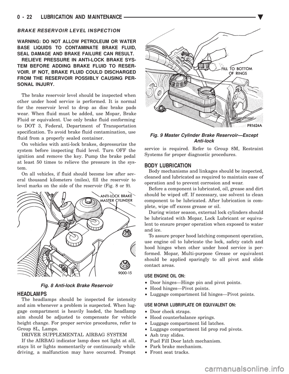
On all vehicles, if fluid should become low after sev-
eral thousand kilometers (miles), fill the reservoir to
level marks on the side of the reservoir (Fig. 8 or 9).
HEADLAMPS
The headlamps should be inspected for intensity
and aim whenever a problem is suspected. When lug-
gage compartment is heavily loaded, the headlamp
aim should be adjusted to compensate for vehicle
height change. For proper service procedures, refer to
Group 8L, Lamps. DRIVER SUPPLEMENTAL AIRBAG SYSTEM
If the AIRBAG indicator lamp does not light at all,
stays lit or lights momentarily or continuously while
driving, a malfunction may have occurred. Prompt service is required. Refer to Group 8M, Restraint
Systems for proper diagnostic procedures.
BODY LUBRICATION
Body mechanisms and linkages should be inspected,
cleaned and lubricated as required to maintain ease of
operation and to prevent corrosion and wear. Before a component is lubricated, oil, grease and dirt
should be wiped off. If necessary, use solvent to clean
component to be lubricated. After lubrication is com-
plete, wipe off excess grease or oil. During winter season, external lock cylinders should
be lubricated with Mopar, Lock Lubricant or equiva-
lent to ensure proper operation when exposed to water
and ice. To assure proper hood latching component operation,
use engine oil to lubricate the lock, safety catch and
hood hinges when other under hood service is per-
formed. Mopar, Multi-purpose Grease or equivalent
should be applied sparingly to all pivot and slide
contact areas.
USE ENGINE OIL ON:
² Door hingesÐHinge pin and pivot points.
² Hood hingesÐPivot points.
² Luggage compartment lid hingesÐPivot points.
USE MOPAR LUBRIPLATE OR EQUIVALENT ON:
² Door check straps.
² Hood counterbalance springs.
² Luggage compartment lid latches.
² Luggage compartment lid prop rod pivots.
² Ash tray slides.
² Fuel Fill Door latch mechanism.
² Park brake mechanism.
² Front seat tracks.
Fig. 8 Anti-lock Brake Reservoir
Fig. 9 Master Cylinder Brake ReservoirÐExcept
Anti-lock
0 - 22 LUBRICATION AND MAINTENANCE Ä
Page 74 of 2438
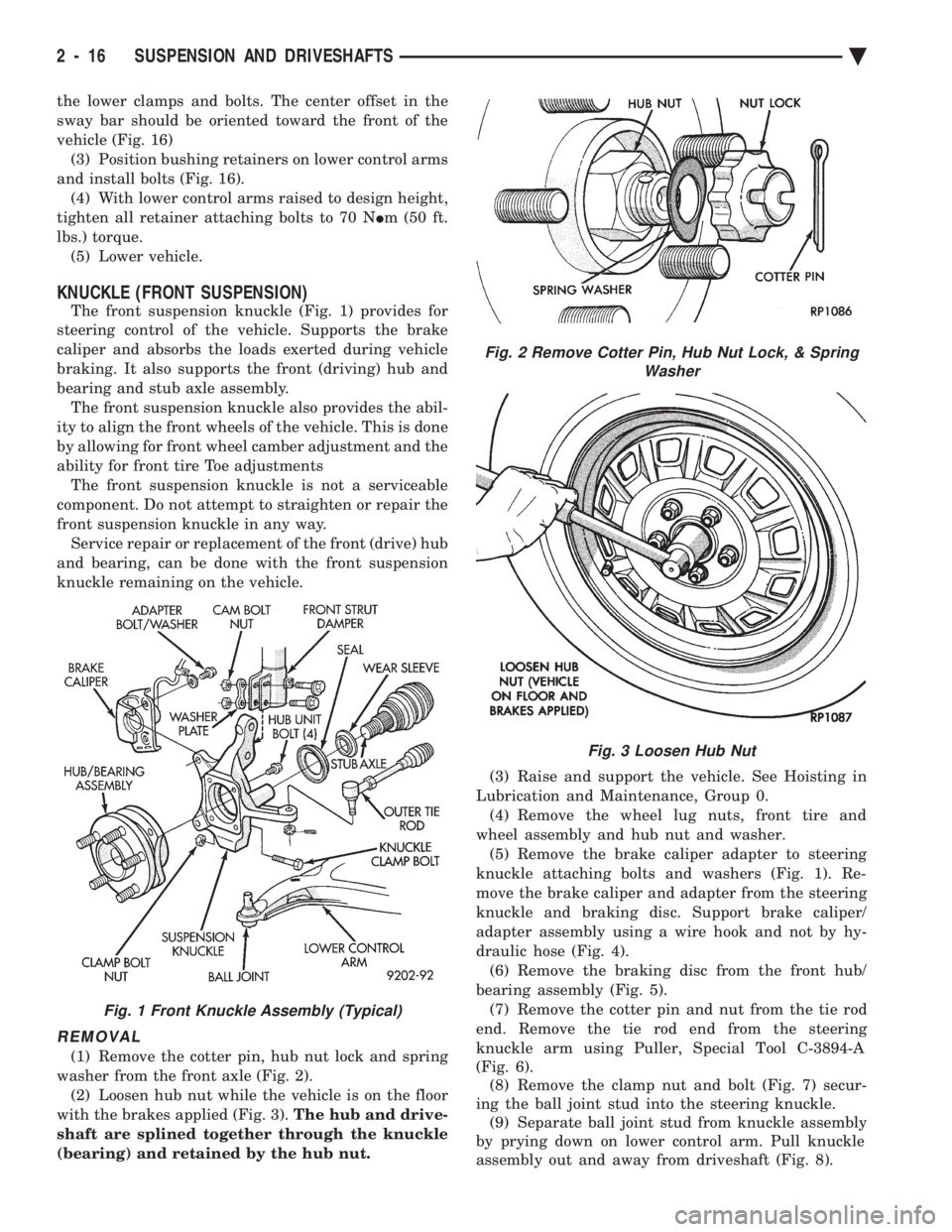
the lower clamps and bolts. The center offset in the
sway bar should be oriented toward the front of the
vehicle (Fig. 16)(3) Position bushing retainers on lower control arms
and install bolts (Fig. 16). (4) With lower control arms raised to design height,
tighten all retainer attaching bolts to 70 N Im (50 ft.
lbs.) torque. (5) Lower vehicle.
KNUCKLE (FRONT SUSPENSION)
The front suspension knuckle (Fig. 1) provides for
steering control of the vehicle. Supports the brake
caliper and absorbs the loads exerted during vehicle
braking. It also supports the front (driving) hub and
bearing and stub axle assembly. The front suspension knuckle also provides the abil-
ity to align the front wheels of the vehicle. This is done
by allowing for front wheel camber adjustment and the
ability for front tire Toe adjustments The front suspension knuckle is not a serviceable
component. Do not attempt to straighten or repair the
front suspension knuckle in any way. Service repair or replacement of the front (drive) hub
and bearing, can be done with the front suspension
knuckle remaining on the vehicle.
REMOVAL
(1) Remove the cotter pin, hub nut lock and spring
washer from the front axle (Fig. 2). (2) Loosen hub nut while the vehicle is on the floor
with the brakes applied (Fig. 3). The hub and drive-
shaft are splined together through the knuckle
(bearing) and retained by the hub nut. (3) Raise and support the vehicle. See Hoisting in
Lubrication and Maintenance, Group 0. (4) Remove the wheel lug nuts, front tire and
wheel assembly and hub nut and washer. (5) Remove the brake caliper adapter to steering
knuckle attaching bolts and washers (Fig. 1). Re-
move the brake caliper and adapter from the steering
knuckle and braking disc. Support brake caliper/
adapter assembly using a wire hook and not by hy-
draulic hose (Fig. 4). (6) Remove the braking disc from the front hub/
bearing assembly (Fig. 5). (7) Remove the cotter pin and nut from the tie rod
end. Remove the tie rod end from the steering
knuckle arm using Puller, Special Tool C-3894-A
(Fig. 6). (8) Remove the clamp nut and bolt (Fig. 7) secur-
ing the ball joint stud into the steering knuckle. (9) Separate ball joint stud from knuckle assembly
by prying down on lower control arm. Pull knuckle
assembly out and away from driveshaft (Fig. 8).
Fig. 2 Remove Cotter Pin, Hub Nut Lock, & Spring Washer
Fig. 3 Loosen Hub Nut
Fig. 1 Front Knuckle Assembly (Typical)
2 - 16 SUSPENSION AND DRIVESHAFTS Ä
Page 77 of 2438
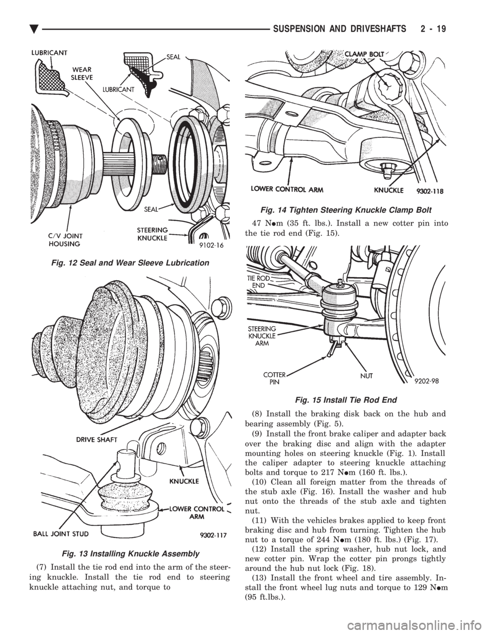
(7) Install the tie rod end into the arm of the steer-
ing knuckle. Install the tie rod end to steering
knuckle attaching nut, and torque to 47 N
Im (35 ft. lbs.). Install a new cotter pin into
the tie rod end (Fig. 15).
(8) Install the braking disk back on the hub and
bearing assembly (Fig. 5). (9) Install the front brake caliper and adapter back
over the braking disc and align with the adapter
mounting holes on steering knuckle (Fig. 1). Install
the caliper adapter to steering knuckle attaching
bolts and torque to 217 N Im (160 ft. lbs.).
(10) Clean all foreign matter from the threads of
the stub axle (Fig. 16). Install the washer and hub
nut onto the threads of the stub axle and tighten
nut. (11) With the vehicles brakes applied to keep front
braking disc and hub from turning. Tighten the hub
nut to a torque of 244 N Im (180 ft. lbs.) (Fig. 17).
(12) Install the spring washer, hub nut lock, and
new cotter pin. Wrap the cotter pin prongs tightly
around the hub nut lock (Fig. 18). (13) Install the front wheel and tire assembly. In-
stall the front wheel lug nuts and torque to 129 N Im
(95 ft.lbs.).
Fig. 13 Installing Knuckle Assembly
Fig. 12 Seal and Wear Sleeve Lubrication
Fig. 14 Tighten Steering Knuckle Clamp Bolt
Fig. 15 Install Tie Rod End
Ä SUSPENSION AND DRIVESHAFTS 2 - 19