instrument cluster CHEVROLET DYNASTY 1993 Service Manual
[x] Cancel search | Manufacturer: CHEVROLET, Model Year: 1993, Model line: DYNASTY, Model: CHEVROLET DYNASTY 1993Pages: 2438, PDF Size: 74.98 MB
Page 266 of 2438
If the vehicle is not set in motion within 3 minutes
from the time the ignition switch is set in the on po-
sition. The solenoid test is bypassed but the pump/
motor is activated briefly to verify that it is
operating correctly.
WARNING SYSTEMS OPERATION
The ABS system uses an Amber Anti-Lock Warn-
ing Lamp, located in the instrument cluster. The
purpose of the warning lamp is discussed in detail
below. The Amber Anti-Lock Warning Light will turn on
when the (CAB) detects a condition which results in
a shutdown of the Anti-Lock function. The Amber
Anti-Lock Warning Lamp is normally on until the
(CAB) completes its self tests and turns the lamp off
(approximately 1-2 seconds). When the Amber Anti-
Lock Warning Light is on only the Anti-Lock func-
tion of the brake system if affected. The standard
brake system and the ability to stop the car will not
be affected when only the Amber Anti-Lock Warning
Light is on.
NORMAL OPERATION OF WARNING LAMP
With the ignition in the Crank position, the Red
Brake Warning Lamp will turn on as a bulb check.
The Amber Anti-Lock Warning Lamp will stay on for
1-2 seconds then turn off. Once verification of the self
diagnosis is completed.
ANTI-LOCK BRAKE SYSTEM COMPONENTS
The following is a detailed description of the Anti-
Lock Brake System components. For information on
servicing the Four Wheel Disk Brake System, see the
standard Brake section of this Service Manual.
MODULATOR ASSEMBLY
WARNING: THE ONLY PART OF THE MODULATOR
ASSEMBLY THAT IS A SERVICEABLE COMPONENT
IS THE DELTA P SWITCH. THE REMAINING COM-
PONENTS OF THE MODULATOR ASSEMBLY ARE
NOT SERVICEABLE ITEMS. NO ATTEMPT SHOULD
BE MADE TO REMOVE OR SERVICE ANY OTHER
PARTS OF THE MODULATOR ASSEMBLY.
The Modulator Assembly (Fig. 1) is located under
the battery tray and is covered with an acid shield.
The Modulator Assembly contains the following com-
ponents for controlling the Anti-Lock braking sys-
tem. 2 Isolation Valves, 4 Build/Decay Valves, 4
Shuttle Orifices, 2 Fluid Sumps, 2 Accumulators, a
Pump/Motor and a Pressure Differential Valve/
Switch. Also attached to the Modulator Assembly are
4 brake tubes which are connected to an 8 way con-
nector block. The connector block is mounted to the
left frame rail below the master cylinder in the same location as the non ABS equipped combination valve.
The wheel brake lines are attached to the system via
the connector block.
ISOLATION VALVES
The Isolation Valves are used to isolate the master
cylinder from the rest of the brake hydraulic circuit
during an Anti-Lock stop. Two Isolation Valves are
used, one for the primary circuit and one for the sec-
ondary circuit. The Isolation Valves are spring
loaded in the released position. In the released posi-
tion the Isolation Valves provide a fluid path from
the master cylinder outputs to the wheel brakes via
the Build/Decay valves. When actuated it provides a
fluid path from the accumulator (which was charged
by the Pump/Motor during ABS operation) to the
Build/Decay valves through the Shuttle Orifices.
BUILD/DECAY VALVES
There are 4 Build/Decay valves, one for each
wheel. In the released position they provide a fluid
path from the wheel brakes to the Isolation Valve
through the shuttle orifices. In the actuated (decay)
position, they provide a fluid path from the wheel
brakes to the sump. The Build/Decay valves are
spring loaded in the released (build) position.
SHUTTLE ORIFICE
There are 4 Shuttle Orifice Valves, one for each
wheel. The Shuttle Orifice Valve is a hydraulically
actuated valve which shuttles when the Build/Decay
valve is actuated. Actuating of the Build/Decay valve
causes a pressure differential to be created across the
Shuttle Orifice Valve. This acts like placing an ori-
fice (restriction) in the line between the Isolation
Valve and the Build/Decay Valve. This restriction
provides a controlled build rate to each wheel brake
during an Anti-Lock stop. The Shuttle Orifice Valve
will remain in the orificed position until the ABS cy-
cle is complete. When the ABS cycle has been com-
pleted the Isolation and Build/Decay valves will
return to their released position which will equalize
the pressure across the Shuttle Orifice Valves. When
the pressure equalizes, the spring loaded Shuttle Or-
ifice valves will return to the unrestricted position.
FLUID SUMPS
There are two Fluid Sumps in the Hydraulic As-
sembly, one each for the primary and secondary hy-
draulic circuits. The Fluid Sumps store the brake
fluid that is decayed from the wheel brakes during
ABS cycle. This fluid is then pumped to an accumu-
lator and/or the hydraulic system in order to provide
build pressure. The typical pressure in the sumps is
50 psi, During ABS operation only.
5 - 116 ANTI-LOCK 6 BRAKE SYSTEM Ä
Page 302 of 2438
(2) The voltage output from each of the wheel
speed sensors is verified to be within the correct op-
erating range. If a vehicle is not set in motion within 3 minutes
from the time the ignition switch is turned to the on
position. The solenoid valve test is bypassed but the
pump/motor is activated briefly to verify that it is op-
erating correctly.
WARNING SYSTEMS OPERATION
The ABS system uses an Amber Antilock Warning
Lamp, located in the instrument cluster. The purpose
of the warning lamp is discussed in detail below. The Amber Antilock Warning Light will turn on
whenever the CAB detects a condition which results
in a shutdown of the Antilock brake system. The
Amber Antilock Warning Lamp is normally on until
the CAB completes its self tests and turns the lamp
off (approximately 1-2 seconds). When the Amber
Antilock Warning Light is on, only the Antilock
brake function of the brake system if affected. The
standard brake system and the ability to stop the car
will not be affected when only the Amber Antilock
Warning Light is on.
NORMAL OPERATION OF WARNING LAMP
With ignition key turned to the Crank position, the
Red Brake Warning Lamp and Amber Antilock
Warning Lamp will turn on as a bulb check. The
Amber Antilock Warning Lamp will stay on for 1-2
seconds then turn off, once verification of Antilock
Brake System self diagnosis is completed.
ANTILOCK BRAKE SYSTEM COMPONENTS
The following is a detailed description of the Ben-
dix Antilock 4 Brake System components. For infor-
mation on servicing the Four Wheel Disc Brake
System, see the standard Brake section in the Front
Wheel Drive Car, chassis service manual.
MODULATOR ASSEMBLY
WARNING: THE ONLY COMPONENTS OF THE
MODULATOR ASSSEMBLY THAT ARE SERVICE-
ABLE, ARE THE 2 PROPORTIONING VALVES,
BLEED SCREWS AND THREAD SAVERS. THE RE-
MAINING COMPONENTS OF THE MODULATOR AS-
SEMBLY ARE NOT INTENDED TO BE
SERVICEABLE ITEMS. NO ATTEMPT SHOULD BE
MADE TO REMOVE OR SERVICE ANY OTHER COM-
PONENTS OF THE MODEULATOR ASSEMBLY.
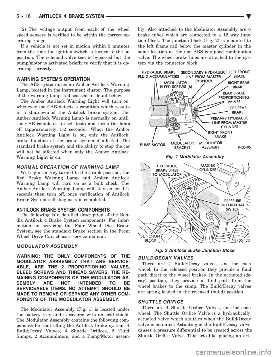
The Modulator Assembly (Fig. 1) is located under
the battery tray and is covered with an acid shield.
The Modulator Assembly contains the following com-
ponents for controlling the Antilock brake system. 4
Build/Decay Valves, 4 Shuttle Orifices, 2 Fluid
Sumps, 2 Accumulators, and a Pump/Motor assem- bly. Also attached to the Modulator Assembly are 6
brake tubes which are connected to a 12 way junc-
tion block. The junction block (Fig. 2) is mounted to
the left frame rail below the master cylinder in the
same location as the non ABS equipped combination
valve. The wheel brake lines are attached to the sys-
tem via the connector block.BUILD/DECAY VALVES
There are 4 Build/Decay valves, one for each
wheel. In the released position they provide a fluid
path direct to the wheel brakes. In the actuated (de-
cay) position, they provide a fluid path from the
wheel brakes to the sump. The Build/Decay valves
are spring loaded in the released (build) position.
SHUTTLE ORIFICE
There are 4 Shuttle Orifice Valves, one for each
wheel. The Shuttle Orifice Valve is a hydraulically
actuated valve which shuttles when the Build/Decay
valve is actuated. Actuating of the Build/Decay valve
causes a pressure differential to be created across the
Shuttle Orifice Valve. This acts like placing an ori-
Fig. 1 Modulator Assembly
Fig. 2 Antilock Brake Junction Block
5 - 16 ANTILOCK 4 BRAKE SYSTEM Ä
Page 373 of 2438
BATTERY/STARTING/CHARGING SYSTEMS DIAGNOSTICS
CONTENTS
page page
BATTERY TEST PROCEDURES ON-VEHICLE . . 3
FAULT CODESÐON BOARD DIAGNOSTICS . . 23
GENERAL INFORMATION .................. 1
GENERATOR TEST PROCEDURES ON VEHICLE.19 IGNITION OFF DRAW (IOD)
............... 9
SPECIFICATIONS ....................... 28
STARTER TEST PROCEDURES ON VEHICLE . 11
GENERAL INFORMATION
² For Battery, Starter or Generator replacement re-
fer to Group 8B, Battery/Starter/Generator Service.
This Group 8A will cover diagnostics only. The Battery, Starting, and Charging Systems oper-
ate with one another, and must be thoroughly tested
as a complete system. To enable the vehicle to start
and charge properly, it must have a battery that will
perform to specifications. The starter motor, genera-
tor, wiring, and electronics also must perform within
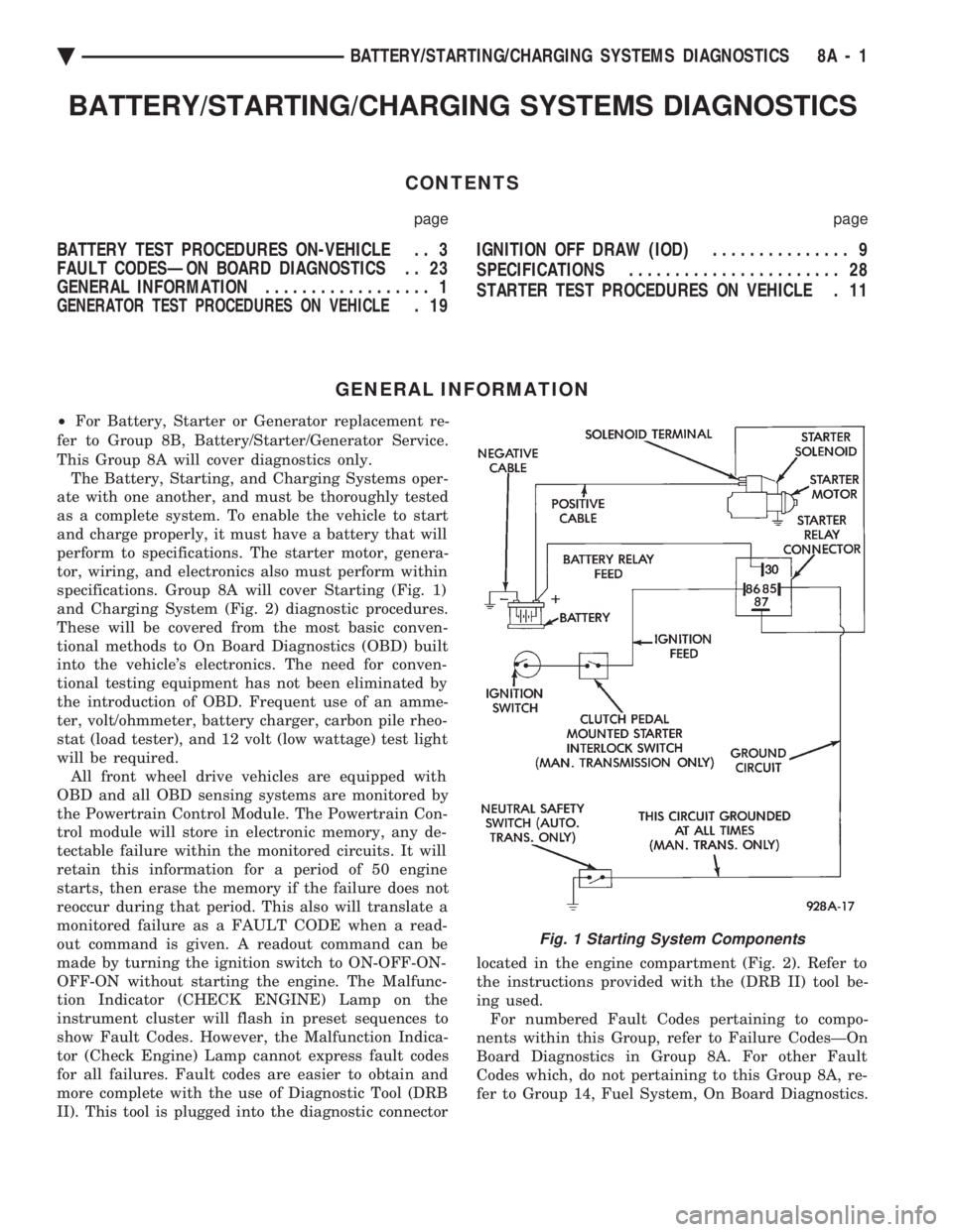
specifications. Group 8A will cover Starting (Fig. 1)
and Charging System (Fig. 2) diagnostic procedures.
These will be covered from the most basic conven-
tional methods to On Board Diagnostics (OBD) built
into the vehicle's electronics. The need for conven-
tional testing equipment has not been eliminated by
the introduction of OBD. Frequent use of an amme-
ter, volt/ohmmeter, battery charger, carbon pile rheo-
stat (load tester), and 12 volt (low wattage) test light
will be required. All front wheel drive vehicles are equipped with
OBD and all OBD sensing systems are monitored by
the Powertrain Control Module. The Powertrain Con-
trol module will store in electronic memory, any de-
tectable failure within the monitored circuits. It will
retain this information for a period of 50 engine
starts, then erase the memory if the failure does not
reoccur during that period. This also will translate a
monitored failure as a FAULT CODE when a read-
out command is given. A readout command can be
made by turning the ignition switch to ON-OFF-ON-
OFF-ON without starting the engine. The Malfunc-
tion Indicator (CHECK ENGINE) Lamp on the
instrument cluster will flash in preset sequences to
show Fault Codes. However, the Malfunction Indica-
tor (Check Engine) Lamp cannot express fault codes
for all failures. Fault codes are easier to obtain and
more complete with the use of Diagnostic Tool (DRB
II). This tool is plugged into the diagnostic connector located in the engine compartment (Fig. 2). Refer to
the instructions provided with the (DRB II) tool be-
ing used. For numbered Fault Codes pertaining to compo-
nents within this Group, refer to Failure CodesÐOn
Board Diagnostics in Group 8A. For other Fault
Codes which, do not pertaining to this Group 8A, re-
fer to Group 14, Fuel System, On Board Diagnostics.
Fig. 1 Starting System Components
Ä BATTERY/STARTING/CHARGING SYSTEMS DIAGNOSTICS 8A - 1
Page 395 of 2438
FAULT CODESÐON BOARD DIAGNOSTICS INDEX
page page
Diagnostic Testing Using Fault Codes ......... 24
Drb II Diagnostic Tester ................... 24 General Description/Information
.............. 23
GENERAL DESCRIPTION/INFORMATION
Another way of diagnosing charging system prob-
lems can be accomplished using the On Board Diag-
nostic System Fault Codes. A Fault Code shows a potential problem in a mon-
itored circuit, or a condition caused by a faulty component. A
Fault Code can be retrieved by turning the ignition
switch ON-OFF-ON-OFF-ON without starting the
engine, and counting the number of flashes of the
Malfunction Indicator (CHECK ENGINE) Lamp in
the instrument cluster.
EXAMPLES:
² If the Malfunction Indicator (Check Engine) Lamp
flashes four times, pauses, and flashes one more
time, a Code 41 is shown. The first set of four flashes
indicates number four. The second set of one flash in-
dicates one.
² If the Malfunction Indicator (Check Engine) Lamp
flashes four times, pauses, and flashes six more
times, a Code 46 is shown. The first set of four
flashes indicates number four. The second set of six
flashes indicates six.
² If the Malfunction Indication (Check Engine)
Lamp flashes four times, pauses, and flashes seven
more times, a Code 47 is shown. The first set of four
flashes indicates number four. The second set of
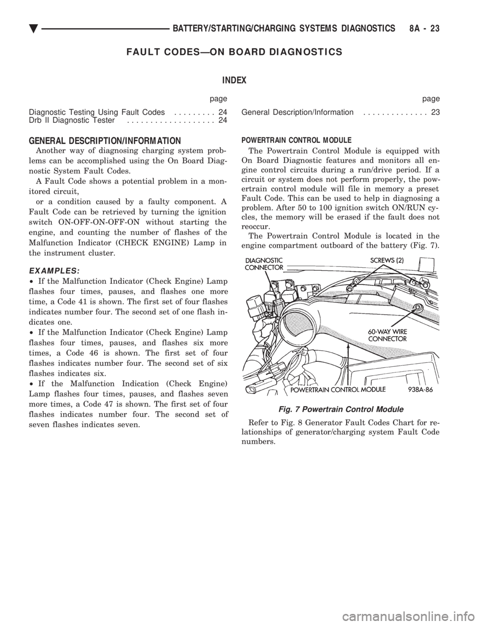
seven flashes indicates seven. POWERTRAIN CONTROL MODULE
The Powertrain Control Module is equipped with
On Board Diagnostic features and monitors all en-
gine control circuits during a run/drive period. If a
circuit or system does not perform properly, the pow-
ertrain control module will file in memory a preset
Fault Code. This can be used to help in diagnosing a
problem. After 50 to 100 ignition switch ON/RUN cy-
cles, the memory will be erased if the fault does not
reoccur. The Powertrain Control Module is located in the
engine compartment outboard of the battery (Fig. 7).
Refer to Fig. 8 Generator Fault Codes Chart for re-
lationships of generator/charging system Fault Code
numbers.
Fig. 7 Powertrain Control Module
Ä BATTERY/STARTING/CHARGING SYSTEMS DIAGNOSTICS 8A - 23
Page 422 of 2438
COMPASS MODULE REPLACEMENT
(1) Remove overhead console.
(2) Using a small screwdriver, release the 2 snaps
at rear of compass module. (3) After releasing the 2 snaps, slide compass mod-
ule rearward until free of mounting bar. (4) For installation reverse above procedures.
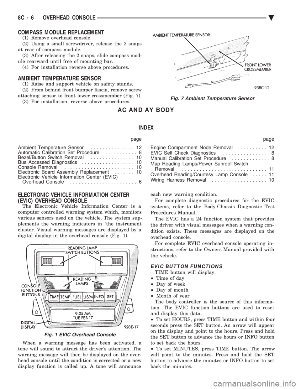
AMBIENT TEMPERATURE SENSOR
(1) Raise and support vehicle on safety stands.
(2) From behind front bumper fascia, remove screw
attaching sensor to front lower crossmember (Fig. 7). (3) For installation, reverse above procedures.
AC AND AY BODY
INDEX
page page
Ambient Temperature Sensor ............... 12
Automatic Calibration Set Procedure ........... 8
Bezel/Button Switch Removal ............... 10
Bus Accessed Diagnostics .................. 10
Console Removal ........................ 10
Electronic Board Assembly Replacement ....... 10
Electronic Vehicle Information Center (EVIC) Overhead Console ....................... 6 Engine Compartment Node Removal
.......... 12
EVIC Self Check Diagnostics ................ 8
Manual Calibration Set Procedure ............. 8
Map Reading Lamps/Power Sunroof Switch Removal .............................. 11
Overhead Reading/Courtesy Lamp Console ..... 11
Wiring Harness Removal ................... 10
ELECTRONIC VEHICLE INFORMATION CENTER
(EVIC) OVERHEAD CONSOLE
The Electronic Vehicle Information Center is a
computer controlled warning system which, monitors
various sensors used on the vehicle. The system sup-
plements the warning indicators in 8the instrument
cluster. Visual warning messages are displayed by a
digital display in the overhead console (Fig. 1).
When a warning message has been activated, a
tone will sound to attract the driver's attention. The
warning message will then be displayed on the over-
head console until the condition is corrected or a new
display function is called up. A tone will announce each new warning condition.
For complete diagnostic procedures for the EVIC
systems, refer to the Body-Chassis Diagnostic Test
Procedures Manual. The EVIC has a 24 function system that provides
the driver with visual messages when a warning con-
dition exists. These messages are displayed on the
overhead console. For complete EVIC overhead console operating in-
structions, refer to the Owners Manual provided with
the vehicle.
EVIC BUTTON FUNCTIONS
TIME button will display:
² Time of day
² Day of week
² Day of month
² Month of year
The body controller is the source of this informa-
tion. The EVIC function buttons are used to reset
and display this data.
² To set HOURS, press TIME button and within four
seconds press the SET button. An arrow will appear
on the display and point to the hours. Press and hold
the SET button to advance the hours or INFO button
to set back the hours.
² To set MINUTES, press TIME button. The arrow
will point to the minutes. Press and hold the SET
button to advance the minutes or INFO button to set
back the minutes.
Fig. 7 Ambient Temperature Sensor
Fig. 1 EVIC Overhead Console
8C - 6 OVERHEAD CONSOLE Ä
Page 429 of 2438
AG AND AJ BODIES INDEX
page page
Ambient Temperature Sensor Removal ......... 20
Compass Calibration ...................... 16
Compass Diagnostics ...................... 18
Compass Module Replacement .............. 20
Demagnetizing Procedure .................. 17
Electronic Vehicle Information Center (EVIC) ..... 13
Electronic Vehicle Information Center (EVIC) Removal .............................. 20 Engine Compartment Node (ECN)
............ 15
Engine Compartment Node Compass Calibration . 16
Engine Node Sensor Removal ............... 20
Map Reading Lamps ...................... 13
Overhead Console Replacement ............. 20
Thermometer and Compass ................. 16
Variance Procedure ....................... 17
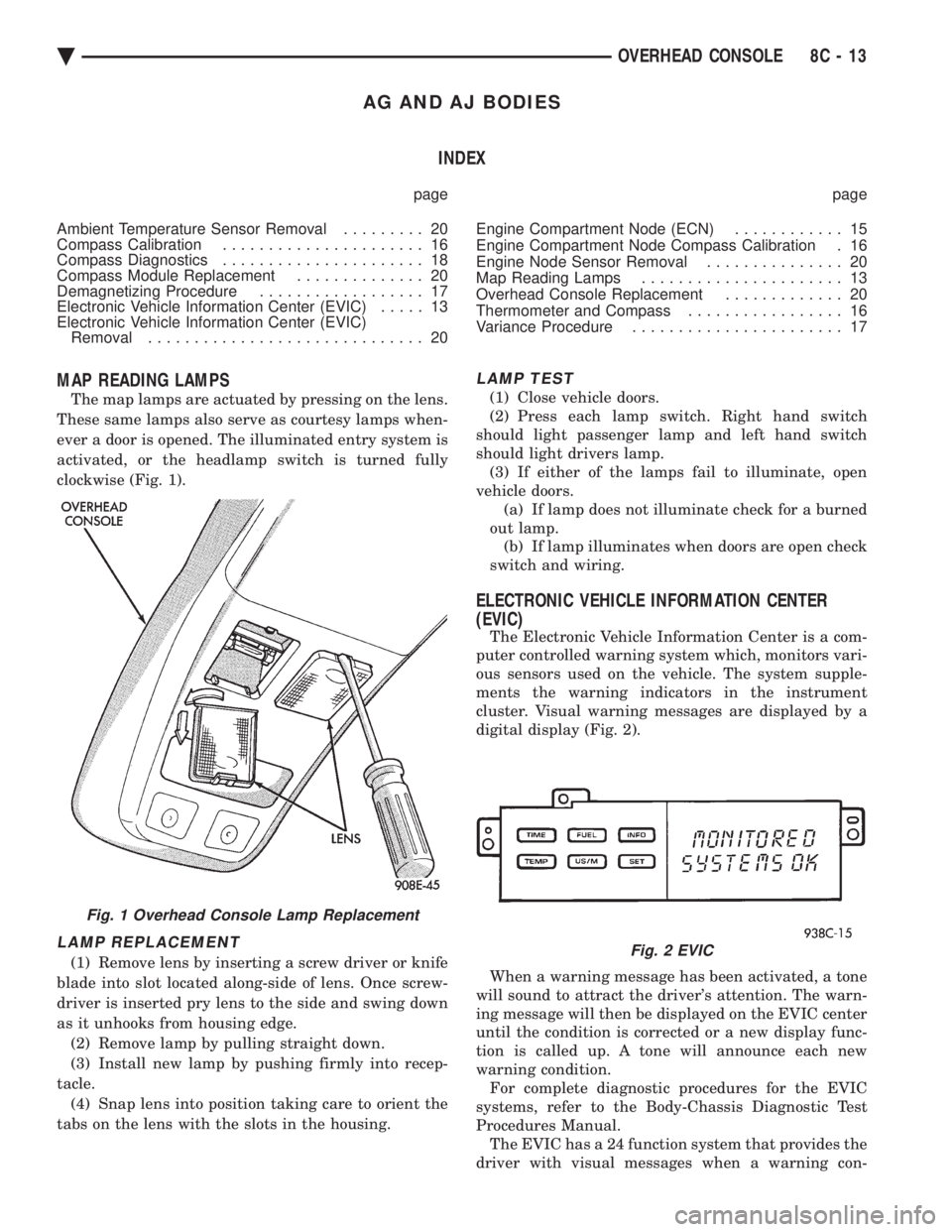
MAP READING LAMPS
The map lamps are actuated by pressing on the lens.
These same lamps also serve as courtesy lamps when-
ever a door is opened. The illuminated entry system is
activated, or the headlamp switch is turned fully
clockwise (Fig. 1).
LAMP REPLACEMENT
(1) Remove lens by inserting a screw driver or knife
blade into slot located along-side of lens. Once screw-
driver is inserted pry lens to the side and swing down
as it unhooks from housing edge. (2) Remove lamp by pulling straight down.
(3) Install new lamp by pushing firmly into recep-
tacle. (4) Snap lens into position taking care to orient the
tabs on the lens with the slots in the housing.
LAMP TEST
(1) Close vehicle doors.
(2) Press each lamp switch. Right hand switch
should light passenger lamp and left hand switch
should light drivers lamp. (3) If either of the lamps fail to illuminate, open
vehicle doors. (a) If lamp does not illuminate check for a burned
out lamp. (b) If lamp illuminates when doors are open check
switch and wiring.
ELECTRONIC VEHICLE INFORMATION CENTER
(EVIC)
The Electronic Vehicle Information Center is a com-
puter controlled warning system which, monitors vari-
ous sensors used on the vehicle. The system supple-
ments the warning indicators in the instrument
cluster. Visual warning messages are displayed by a
digital display (Fig. 2).
When a warning message has been activated, a tone
will sound to attract the driver's attention. The warn-
ing message will then be displayed on the EVIC center
until the condition is corrected or a new display func-
tion is called up. A tone will announce each new
warning condition. For complete diagnostic procedures for the EVIC
systems, refer to the Body-Chassis Diagnostic Test
Procedures Manual. The EVIC has a 24 function system that provides the
driver with visual messages when a warning con-
Fig. 1 Overhead Console Lamp Replacement
Fig. 2 EVIC
Ä OVERHEAD CONSOLE 8C - 13
Page 493 of 2438
INSTRUMENT PANEL AND GAUGES
CONTENTS
page page
AA BODY .............................. 1
AC AND AY BODIES .................... 23 AG AND AJ BODIES
.................... 42
AP BODY ............................. 58
AA BODY INDEX
page page
Cluster and Gauge Service and Testing ........ 2
Electronic Cluster ........................ 13
Fuel GaugeÐFlexible Fuel .................. 2
Gauges ................................. 7
General Information ........................ 1 Instrument Panel
......................... 21
Interior Lamp Replacement ................. 21
Mechanical/Electronic Cluster Removal ......... 5
Switch and Panel Component Service ......... 15
GENERAL INFORMATION
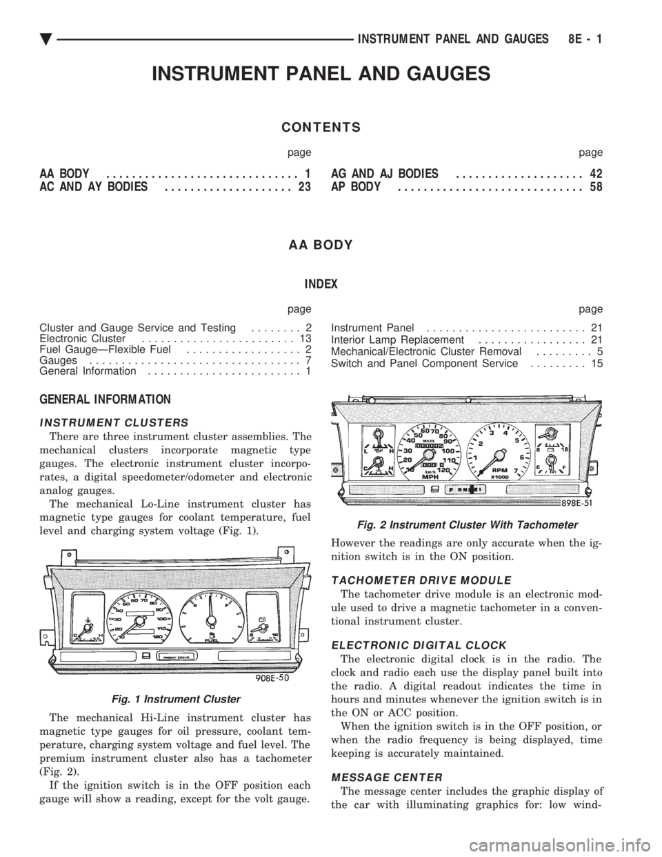
INSTRUMENT CLUSTERS
There are three instrument cluster assemblies. The
mechanical clusters incorporate magnetic type
gauges. The electronic instrument cluster incorpo-
rates, a digital speedometer/odometer and electronic
analog gauges. The mechanical Lo-Line instrument cluster has
magnetic type gauges for coolant temperature, fuel
level and charging system voltage (Fig. 1).
The mechanical Hi-Line instrument cluster has
magnetic type gauges for oil pressure, coolant tem-
perature, charging system voltage and fuel level. The
premium instrument cluster also has a tachometer
(Fig. 2). If the ignition switch is in the OFF position each
gauge will show a reading, except for the volt gauge. However the readings are only accurate when the ig-
nition switch is in the ON position.
TACHOMETER DRIVE MODULE
The tachometer drive module is an electronic mod-
ule used to drive a magnetic tachometer in a conven-
tional instrument cluster.
ELECTRONIC DIGITAL CLOCK
The electronic digital clock is in the radio. The
clock and radio each use the display panel built into
the radio. A digital readout indicates the time in
hours and minutes whenever the ignition switch is in
the ON or ACC position. When the ignition switch is in the OFF position, or
when the radio frequency is being displayed, time
keeping is accurately maintained.
MESSAGE CENTER
The message center includes the graphic display of
the car with illuminating graphics for: low wind-
Fig. 1 Instrument Cluster
Fig. 2 Instrument Cluster With Tachometer
Ä INSTRUMENT PANEL AND GAUGES 8E - 1
Page 494 of 2438
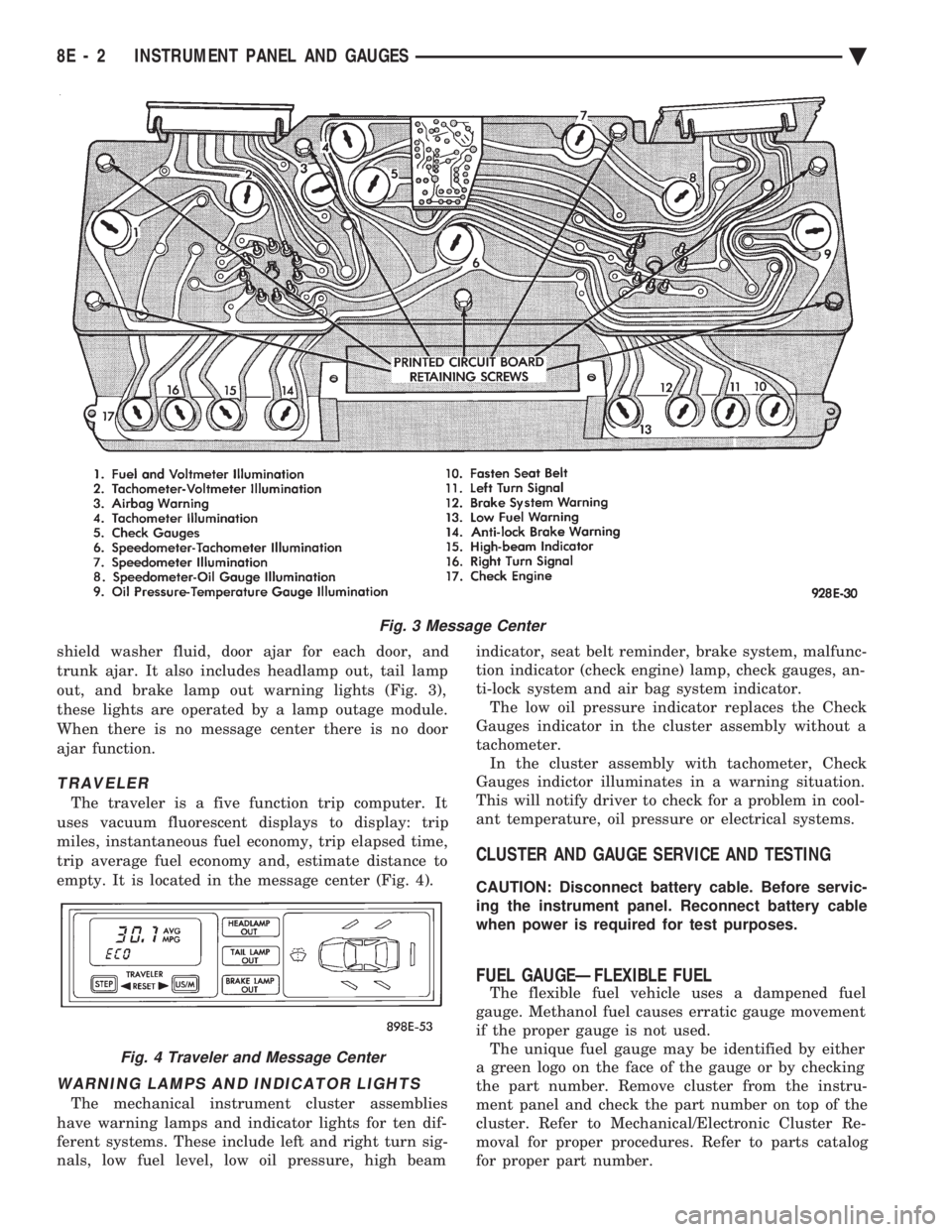
shield washer fluid, door ajar for each door, and
trunk ajar. It also includes headlamp out, tail lamp
out, and brake lamp out warning lights (Fig. 3),
these lights are operated by a lamp outage module.
When there is no message center there is no door
ajar function.
TRAVELER
The traveler is a five function trip computer. It
uses vacuum fluorescent displays to display: trip
miles, instantaneous fuel economy, trip elapsed time,
trip average fuel economy and, estimate distance to
empty. It is located in the message center (Fig. 4).
WARNING LAMPS AND INDICATOR LIGHTS
The mechanical instrument cluster assemblies
have warning lamps and indicator lights for ten dif-
ferent systems. These include left and right turn sig-
nals, low fuel level, low oil pressure, high beam indicator, seat belt reminder, brake system, malfunc-
tion indicator (check engine) lamp, check gauges, an-
ti-lock system and air bag system indicator. The low oil pressure indicator replaces the Check
Gauges indicator in the cluster assembly without a
tachometer. In the cluster assembly with tachometer, Check
Gauges indictor illuminates in a warning situation.
This will notify driver to check for a problem in cool-
ant temperature, oil pressure or electrical systems.
CLUSTER AND GAUGE SERVICE AND TESTING
CAUTION: Disconnect battery cable. Before servic-
ing the instrument panel. Reconnect battery cable
when power is required for test purposes.
FUEL GAUGEÐFLEXIBLE FUEL
The flexible fuel vehicle uses a dampened fuel
gauge. Methanol fuel causes erratic gauge movement
if the proper gauge is not used. The unique fuel gauge may be identified by either
a green logo on the face of the gauge or by checking
the part number. Remove cluster from the instru-
ment panel and check the part number on top of the
cluster. Refer to Mechanical/Electronic Cluster Re-
moval for proper procedures. Refer to parts catalog
for proper part number.
Fig. 3 Message Center
Fig. 4 Traveler and Message Center
8E - 2 INSTRUMENT PANEL AND GAUGES Ä
Page 495 of 2438
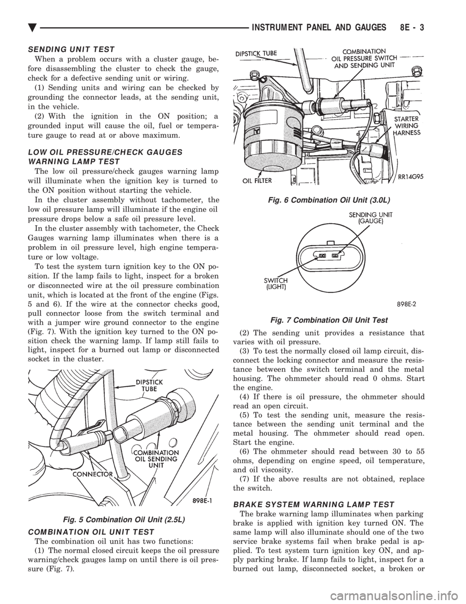
SENDING UNIT TEST
When a problem occurs with a cluster gauge, be-
fore disassembling the cluster to check the gauge,
check for a defective sending unit or wiring. (1) Sending units and wiring can be checked by
grounding the connector leads, at the sending unit,
in the vehicle. (2) With the ignition in the ON position; a
grounded input will cause the oil, fuel or tempera-
ture gauge to read at or above maximum.
LOW OIL PRESSURE/CHECK GAUGES WARNING LAMP TEST
The low oil pressure/check gauges warning lamp
will illuminate when the ignition key is turned to
the ON position without starting the vehicle. In the cluster assembly without tachometer, the
low oil pressure lamp will illuminate if the engine oil
pressure drops below a safe oil pressure level. In the cluster assembly with tachometer, the Check
Gauges warning lamp illuminates when there is a
problem in oil pressure level, high engine tempera-
ture or low voltage. To test the system turn ignition key to the ON po-
sition. If the lamp fails to light, inspect for a broken
or disconnected wire at the oil pressure combination
unit, which is located at the front of the engine (Figs.
5 and 6). If the wire at the connector checks good,
pull connector loose from the switch terminal and
with a jumper wire ground connector to the engine
(Fig. 7). With the ignition key turned to the ON po-
sition check the warning lamp. If lamp still fails to
light, inspect for a burned out lamp or disconnected
socket in the cluster.
COMBINATION OIL UNIT TEST
The combination oil unit has two functions:
(1) The normal closed circuit keeps the oil pressure
warning/check gauges lamp on until there is oil pres-
sure (Fig. 7). (2) The sending unit provides a resistance that
varies with oil pressure. (3) To test the normally closed oil lamp circuit, dis-
connect the locking connector and measure the resis-
tance between the switch terminal and the metal
housing. The ohmmeter should read 0 ohms. Start
the engine. (4) If there is oil pressure, the ohmmeter should
read an open circuit. (5) To test the sending unit, measure the resis-
tance between the sending unit terminal and the
metal housing. The ohmmeter should read open.
Start the engine. (6) The ohmmeter should read between 30 to 55
ohms, depending on engine speed, oil temperature,
and oil viscosity. (7) If the above results are not obtained, replace
the switch.
BRAKE SYSTEM WARNING LAMP TEST
The brake warning lamp illuminates when parking
brake is applied with ignition key turned ON. The
same lamp will also illuminate should one of the two
service brake systems fail when brake pedal is ap-
plied. To test system turn ignition key ON, and ap-
ply parking brake. If lamp fails to light, inspect for a
burned out lamp, disconnected socket, a broken orFig. 5 Combination Oil Unit (2.5L)
Fig. 6 Combination Oil Unit (3.0L)
Fig. 7 Combination Oil Unit Test
Ä INSTRUMENT PANEL AND GAUGES 8E - 3
Page 497 of 2438
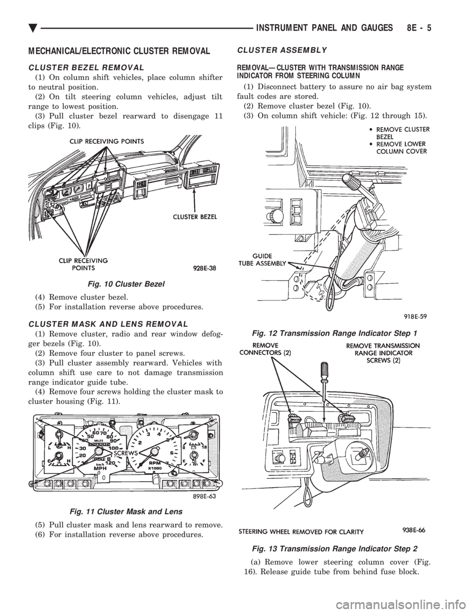
MECHANICAL/ELECTRONIC CLUSTER REMOVAL
CLUSTER BEZEL REMOVAL
(1) On column shift vehicles, place column shifter
to neutral position. (2) On tilt steering column vehicles, adjust tilt
range to lowest position. (3) Pull cluster bezel rearward to disengage 11
clips (Fig. 10).
(4) Remove cluster bezel.
(5) For installation reverse above procedures.
CLUSTER MASK AND LENS REMOVAL
(1) Remove cluster, radio and rear window defog-
ger bezels (Fig. 10). (2) Remove four cluster to panel screws.
(3) Pull cluster assembly rearward. Vehicles with
column shift use care to not damage transmission
range indicator guide tube. (4) Remove four screws holding the cluster mask to
cluster housing (Fig. 11).
(5) Pull cluster mask and lens rearward to remove.
(6) For installation reverse above procedures.
CLUSTER ASSEMBLY
REMOVALÐCLUSTER WITH TRANSMISSION RANGE
INDICATOR FROM STEERING COLUMN
(1) Disconnect battery to assure no air bag system
fault codes are stored. (2) Remove cluster bezel (Fig. 10).
(3) On column shift vehicle: (Fig. 12 through 15).
(a) Remove lower steering column cover (Fig.
16). Release guide tube from behind fuse block.
Fig. 10 Cluster Bezel
Fig. 11 Cluster Mask and Lens
Fig. 12 Transmission Range Indicator Step 1
Fig. 13 Transmission Range Indicator Step 2
Ä INSTRUMENT PANEL AND GAUGES 8E - 5