wheel size CHEVROLET DYNASTY 1993 Service Manual
[x] Cancel search | Manufacturer: CHEVROLET, Model Year: 1993, Model line: DYNASTY, Model: CHEVROLET DYNASTY 1993Pages: 2438, PDF Size: 74.98 MB
Page 63 of 2438
FRONT SUSPENSION SERVICE PROCEDURES INDEX
page page
Ball Joints .............................. 13
Hub and Bearing Assembly ................. 20
Knuckle (Front Suspension) ................. 16
Lower Control Arm ....................... 10
Lower Control Arm Pivot Bushings ........... 11 Shock Absorbers (Strut Damper)
............. 10
Strut Damper Assembly ..................... 7
Suspension Coil Springs .................... 9
Sway Bar .............................. 14
Wheel Alignment .......................... 5
WHEEL ALIGNMENT
Front wheel alignment is the proper adjustment of
all interrelated front suspension angles. These angles
are what affects the running and steering of the
front wheels of the vehicle. The method of checking front alignment will vary
depending on the type of equipment being used. The
instructions furnished by the manufacturer of the
equipment should always be followed. With the ex-
ception that the alignment specifications recom-
mended by Chrysler Corporation be used. There are six basic factors which are the founda-
tion to front wheel alignment. These are height,
caster, camber, toe-in, steering axis inclination and
toe-out on turns. Of the six basic factors only camber
and toe in are mechanically adjustable (Fig. 1)
CAUTION: Do not attempt to modify any suspen-
sion or steering components by heating or bending
of the component.
Wheel alignment adjustments and checks should be
made in the following sequence. (1) Camber
(2) Toe
Camber is the number of degrees the top of the
wheel is tilted inward or outward from true vertical.
Inward tilt is negative camber. Outward tilt is posi-
tive camber. Excessive camber is a tire wear factor: negative
camber causes wear on the inside of the tire, while
positive camber causes wear to the outside. Toe
is measured in degrees or inches and is the
distance the front edges of the tires are closer (or far-
ther apart) than the rear edges. See Front Wheel
Drive Specifications for Toesettings.
PRE-ALIGNMENT
Before any attempt is made to change or correct
the wheel alignment factors. The following inspection
and necessary corrections must be made on those
parts which influence the steering of the vehicle. (1) Check and inflate tires to recommended pres-
sure. All tires should be the same size and in good
condition and have approximately the same wear.
Note type of tread wear which will aid in diagnosing,
see Wheels and Tires, Group 22. (2) Check front wheel and tire assembly for radial
runout. (3) Inspect lower ball joints and all steering link-
age for looseness. (4) Check for broken or sagged front and rear
springs. Front suspension must only be checked after the
vehicle has had the following checked or adjusted.
Tires set to recommended pressures, full tank of fuel,
no passenger or luggage compartment load and is on
a level floor or alignment rack. Just prior to each alignment reading. The vehicle
should be bounced (rear first, then front) by grasping
bumper at center and jouncing each end an equal
number of times. Always release bumpers at bottom
of down cycle.
Ä SUSPENSION AND DRIVESHAFTS 2 - 5
Page 78 of 2438
(14) Lower vehicle.
(15) Align the front wheels of the vehicle. Use the
procedure listed under Wheel Alignment, in the
Front Suspension Service Procedures section of this
service manual.
HUB AND BEARING ASSEMBLY
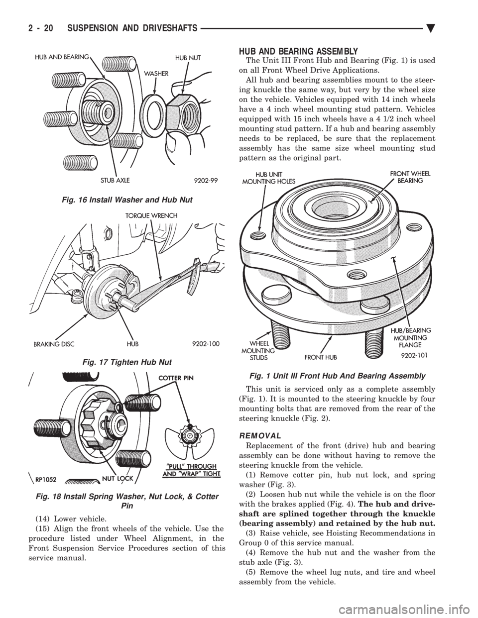
The Unit III Front Hub and Bearing (Fig. 1) is used
on all Front Wheel Drive Applications. All hub and bearing assemblies mount to the steer-
ing knuckle the same way, but very by the wheel size
on the vehicle. Vehicles equipped with 14 inch wheels
have a 4 inch wheel mounting stud pattern. Vehicles
equipped with 15 inch wheels hav e a 4 1/2 inch wheel
mounting stud pattern. If a hub and bearing assembly
needs to be replaced, be sure that the replacement
assembly has the same size wheel mounting stud
pattern as the original part.
This unit is serviced only as a complete assembly
(Fig. 1). It is mounted to the steering knuckle by four
mounting bolts that are removed from the rear of the
steering knuckle (Fig. 2).
REMOVAL
Replacement of the front (drive) hub and bearing
assembly can be done without having to remove the
steering knuckle from the vehicle. (1) Remove cotter pin, hub nut lock, and spring
washer (Fig. 3). (2) Loosen hub nut while the vehicle is on the floor
with the brakes applied (Fig. 4). The hub and drive-
shaft are splined together through the knuckle
(bearing assembly) and retained by the hub nut. (3) Raise vehicle, see Hoisting Recommendations in
Group 0 of this service manual. (4) Remove the hub nut and the washer from the
stub axle (Fig. 3). (5) Remove the wheel lug nuts, and tire and wheel
assembly from the vehicle.
Fig. 16 Install Washer and Hub Nut
Fig. 17 Tighten Hub Nut
Fig. 18 Install Spring Washer, Nut Lock, & Cotter Pin
Fig. 1 Unit III Front Hub And Bearing Assembly
2 - 20 SUSPENSION AND DRIVESHAFTS Ä
Page 151 of 2438
BRAKES
CONTENTS
page page
ANTI-LOCK BRAKE SYSTEMÐBENDIX ANTI-LOCK 10 AC/Y BODY ............. 72
ANTI-LOCK BRAKE SYSTEMÐBENDIX ANTI-LOCK 6 AA,AG,AJ,AP BODY ....... 113
BRAKE DISC (ROTOR) ................... 53
BRAKE SUPPORT ASSEMBLY ............. 25
FRONT DISC BRAKES ................... 31
GENERAL INFORMATION .................. 1
HYDRAULIC SYSTEM CONTROL VALVES . . . 26
KELSEY HAYES DOUBLE PIN FAMILY CALIPER ............................ 35 KELSEY HAYES DOUBLE PIN NON-FAMILY
CALIPER ............................ 38
MASTER CYLINDER ..................... 66
PARKING BRAKES ...................... 57
POWER BRAKES ....................... 68
REAR DISC BRAKES .................... 45
REAR WHEEL DRUM BRAKES ............ 18
SERVICE ADJUSTMENTS .................. 4
WHEEL BEARINGS ...................... 70
WHEEL CYLINDERS ..................... 23
GENERAL INFORMATION
Throughout this group, references may be made to
a particular vehicle by letter or number designation.
A chart showing the break down of these designa-
tions is included in the Introduction Section at the
front of this service manual. Standard brake equipment consists of:
² Double pin floating caliper disc front brakes.
² Rear automatic adjusting drum brakes.
² Differential valve with a brake warning switch.
² Master cylinder.
² Vacuum power booster.
² Double pin floating caliper rear disc brakes are
available on some models. The Bendix Anti-Lock 10 braking system, uses the
standard power brake system caliper assemblies,
braking discs, pedal assembly, brake lines and hoses.
The unique parts of the Bendix Anti-Lock 10 braking
system consists of the following components. Propor-
tioning valves, wheel speed sensors, tone wheels,
electronic control unit, modulator assembly and hy-
draulic assembly. These components replace the con-
ventional master cylinder and power booster. The
components will be described in detail in the Bendix
Anti-Lock 10 brake section in this group of the ser-
vice manual. The Bendix Anti-Lock 6 braking system, uses the
following standard brake system components. Master
cylinder, power booster, caliper assemblies, braking
discs, pedal assembly, brake lines and hoses. The
unique parts of the Bendix Anti-Lock 6 braking sys-
tem consists of the following components. Modulator
assembly, unique proportioning valves, wheel speed
sensors, tone wheels, and electronic control unit.
These components will be described in detail in the
Bendix Anti-Lock 6 brake section in this group of the
service manual. The front disc brake shoes have semi-metallic lin-
ings. The hydraulic brake system (Fig .123and4)is
diagonally split on both the Non-ABS and ABS brak-
ing system. With the left front and right rear brakes
on one hydraulic system and the right front and left
rear on the other. The Non-ABS and ABS brake system may use dif-
ferent types of brake line fittings and tubing flares.
The Non-ABS brake system uses double wall tubing
flares and fittings at all tubing joint locations. Some
ABS brake systems use both ISO style tubing flares
and double wall tubing flares and corresponding fit-
tings at different joint locations. See (Figs . 2 3 and 4)
for specific joint locations and type of tubing flare. The front disc brakes consist of two different types
of caliper assemblies. A double pin Kelsey-Hayes cal-
iper (family caliper) with a bolt-on adapter attached
to the steering knuckle. Or a double pin Kelsey-
Hayes caliper (non-family caliper) which mounts di-
rectly to rails on the steering knuckle. The non-
family caliper is only used on the AY Body
(Imperials).
CAUTION: Caliper pistons, boots and seals for the
different caliper assemblies used on the front and
rear disc brake assemblies are not interchangeable.
Misusage could result in a complete brake system
failure. Be sure that the parts are replaced with the
correct replacement parts, refer to the parts book
for the type and model year of the vehicle being
worked on.
The master cylinder is anodized, lightweight alu-
minum, with a bore size of 24.0mm, 21.0mm or 7/8
inch.
Ä BRAKES 5 - 1
Page 161 of 2438
BRAKE HOSE AND TUBING
INSPECTION OF BRAKE HOSE AND TUBING
Flexible rubber hose is used at both front brakes and
at the rear axle. Inspection of brake hoses should be
performed whenever the brake system is serviced and
every 7,500 miles or 12 months, whichever comes first
(every engine oil change). Inspect hydraulic brake
hoses for severe surface cracking, scuffing, or worn
spots. Should the fabric casing of the rubber hose be
exposed due to cracks or abrasions in the rubber hose
cover, the hose should be replaced immediately. Even-
tual deterioration of the hose can take place with
possible burst failure. Faulty installation can cause
twisting and wheel, tire or chassis interference. The steel brake tubing should be inspected periodi-
cally for evidence of physical damage or contact with
moving or hot components.
INSTALLATION OF BRAKE HOSE
Always use factory recommended brake hose to en-
sure quality, correct length and superior fatigue life.
Care should be taken to make sure that the tube and
hose mating surfaces are clean and free from nicks and
burrs. Front right and left side hoses are not
interchangeable. Connections should be correct and properly made.
Use new copper seal washers on all connections using
Banjo Bolts and tighten all fittings to their specified
torques. The flexible front hydraulic brake hose should al-
ways be installed on the vehicle by first attaching the
Banjo connector to the caliper assembly. Then bolt the
intermediate hose bracket to the strut assembly allow-
ing the bracket to position the hose to prevent twisting.
Attach the hose to the body bracket and steel brake
tubing. Tighten all fittings to specified torque. The
body bracket and hose end are keyed so that they will
only fit one way. Install rear brake hoses first to the trailing arm
tubes and then to the floor pan tubes. Minimize hose
twisting. Vehicles equipped with rear disc brakes have
brake hoses attached to the caliper on each side. The
brake hose should be first attached by the Banjo bolt to
the caliper and then secured to the hose bracket with
the retaining clip. The attach the steel brake tubing to
the hose fitting.
REPAIR AND INSTALLATION OF BRAKE TUB- ING
Only double wall 4.75mm (3/16 in.) steel tubing
should be used for replacement. Care should be taken
when replacing brake tubing, to be sure the proper
bending and flaring tools and procedures are used, to
avoid kinking. Do not route the tubes against sharp edges, moving components or into hot areas. All
tubes should be properly attached with recommended
retaining clips.
TYPES OF TUBING FLARES
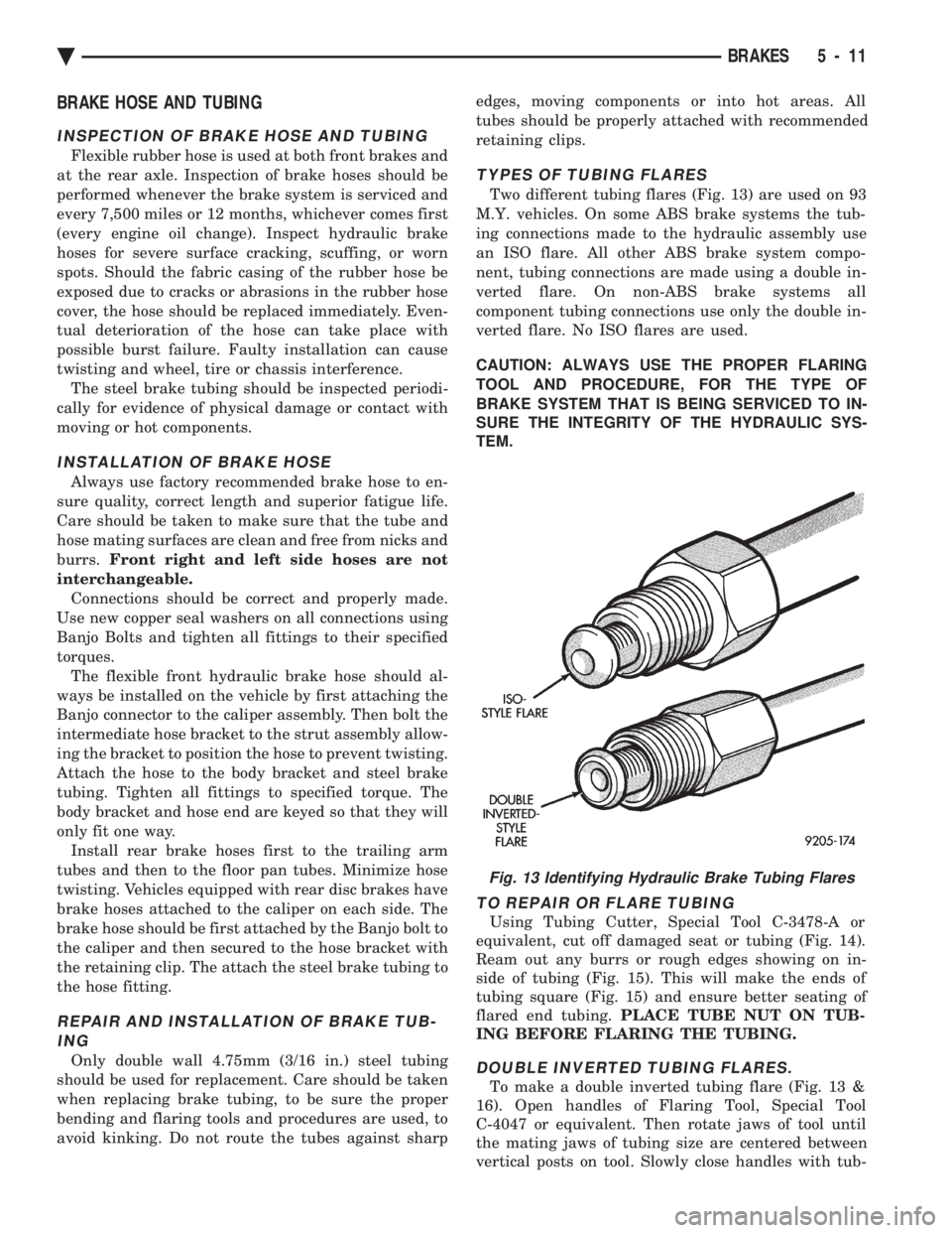
Two different tubing flares (Fig. 13) are used on 93
M.Y. vehicles. On some ABS brake systems the tub-
ing connections made to the hydraulic assembly use
an ISO flare. All other ABS brake system compo-
nent, tubing connections are made using a double in-
verted flare. On non-ABS brake systems all
component tubing connections use only the double in-
verted flare. No ISO flares are used.
CAUTION: ALWAYS USE THE PROPER FLARING
TOOL AND PROCEDURE, FOR THE TYPE OF
BRAKE SYSTEM THAT IS BEING SERVICED TO IN-
SURE THE INTEGRITY OF THE HYDRAULIC SYS-
TEM.
TO REPAIR OR FLARE TUBING
Using Tubing Cutter, Special Tool C-3478-A or
equivalent, cut off damaged seat or tubing (Fig. 14).
Ream out any burrs or rough edges showing on in-
side of tubing (Fig. 15). This will make the ends of
tubing square (Fig. 15) and ensure better seating of
flared end tubing. PLACE TUBE NUT ON TUB-
ING BEFORE FLARING THE TUBING.
DOUBLE INVERTED TUBING FLARES.
To make a double inverted tubing flare (Fig. 13 &
16). Open handles of Flaring Tool, Special Tool
C-4047 or equivalent. Then rotate jaws of tool until
the mating jaws of tubing size are centered between
vertical posts on tool. Slowly close handles with tub-
Fig. 13 Identifying Hydraulic Brake Tubing Flares
Ä BRAKES 5 - 11
Page 195 of 2438
REAR DISC BRAKES INDEX
page page
Assembling Rear Disc Brake Caliper .......... 49
Brake Shoe Removal ..................... 46
Cleaning and Inspection ................... 49
Disassembling Rear Caliper Assembly ......... 48 General Information
....................... 45
Lining Wear ............................. 45
Service Precautions ....................... 46
GENERAL INFORMATION
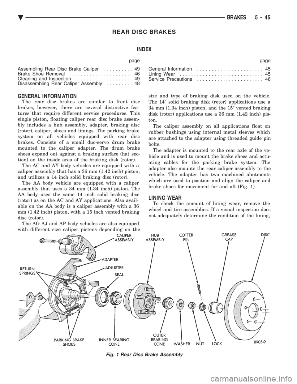
The rear disc brakes are similar to front disc
brakes, however, there are several distinctive fea-
tures that require different service procedures. This
single piston, floating caliper rear disc brake assem-
bly includes a hub assembly, adapter, braking disc
(rotor), caliper, shoes and linings. The parking brake
system on all vehicles equipped with rear disc
brakes. Consists of a small duo-servo drum brake
mounted to the caliper adapter. The drum brake
shoes expand out against a braking surface (hat sec-
tion) on the inside area of the braking disk (rotor). The AC and AY body vehicles are equipped with a
caliper assembly that has a 36 mm (1.42 inch) piston,
and utilizes a 14 inch solid braking disc (rotor). The AA body vehicle are equipped with a caliper
assembly that uses a 34 mm (1.34 inch) piston. The
AA body uses the same 14 inch solid braking disc
(rotor) as on the AC and AY applications. Also avail-
able on the AA body is a caliper assembly with a 36
mm (1.42 inch) piston, with a 15 inch vented braking
disc (rotor). The AG AJ and AP body vehicles are also equipped
with different size caliper pistons depending on the size and type of braking disk used on the vehicle.
The 14 9solid braking disk (rotor) applications use a
34 mm (1.34 inch) piston, and the 15 9vented braking
disk (rotor) applications use a 36 mm (1.42 inch) pis-
ton. The caliper assembly on all applications float on
rubber bushings using internal metal sleeves which
are attached to the adapter using threaded guide pin
bolts. The adapter is mounted to the rear axle of the ve-
hicle and is used to mount the brake shoes and actu-
ating cables for the parking brake system. The
adapter also mounts the rear caliper assembly to the
vehicle. The adapter has two machined abutments
which are used to position and align the caliper and
brake shoes for movement for and aft (Fig. 1)
LINING WEAR
To check the amount of lining wear, remove the
wheel and tire assemblies. If a visual inspection does
not adequately determine the condition of the lining,
Fig. 1 Rear Disc Brake Assembly
Ä BRAKES 5 - 45
Page 230 of 2438
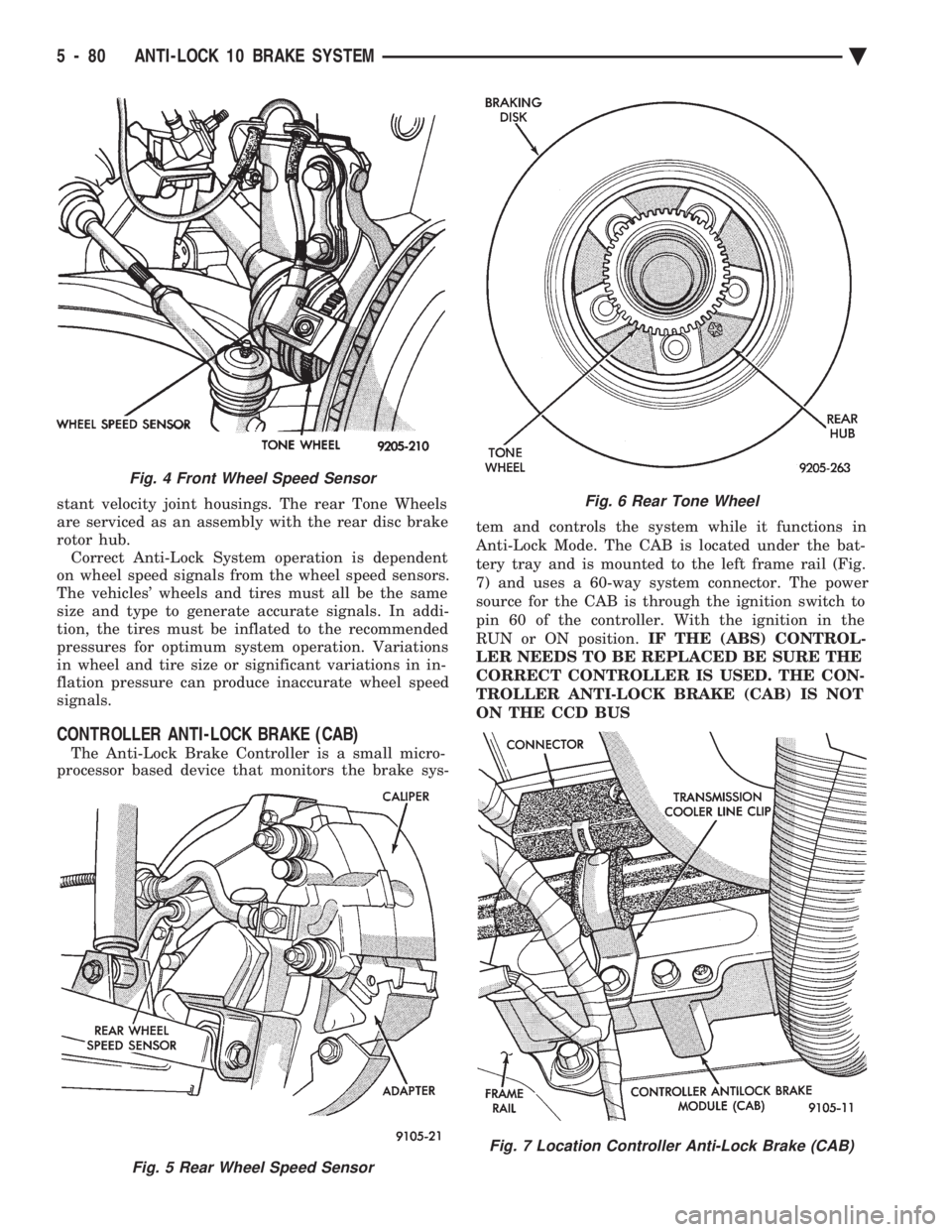
stant velocity joint housings. The rear Tone Wheels
are serviced as an assembly with the rear disc brake
rotor hub. Correct Anti-Lock System operation is dependent
on wheel speed signals from the wheel speed sensors.
The vehicles' wheels and tires must all be the same
size and type to generate accurate signals. In addi-
tion, the tires must be inflated to the recommended
pressures for optimum system operation. Variations
in wheel and tire size or significant variations in in-
flation pressure can produce inaccurate wheel speed
signals.
CONTROLLER ANTI-LOCK BRAKE (CAB)
The Anti-Lock Brake Controller is a small micro-
processor based device that monitors the brake sys- tem and controls the system while it functions in
Anti-Lock Mode. The CAB is located under the bat-
tery tray and is mounted to the left frame rail (Fig.
7) and uses a 60-way system connector. The power
source for the CAB is through the ignition switch to
pin 60 of the controller. With the ignition in the
RUN or ON position. IF THE (ABS) CONTROL-
LER NEEDS TO BE REPLACED BE SURE THE
CORRECT CONTROLLER IS USED. THE CON-
TROLLER ANTI-LOCK BRAKE (CAB) IS NOT
ON THE CCD BUS
Fig. 5 Rear Wheel Speed Sensor
Fig. 4 Front Wheel Speed Sensor
Fig. 6 Rear Tone Wheel
Fig. 7 Location Controller Anti-Lock Brake (CAB)
5 - 80 ANTI-LOCK 10 BRAKE SYSTEM Ä
Page 268 of 2438
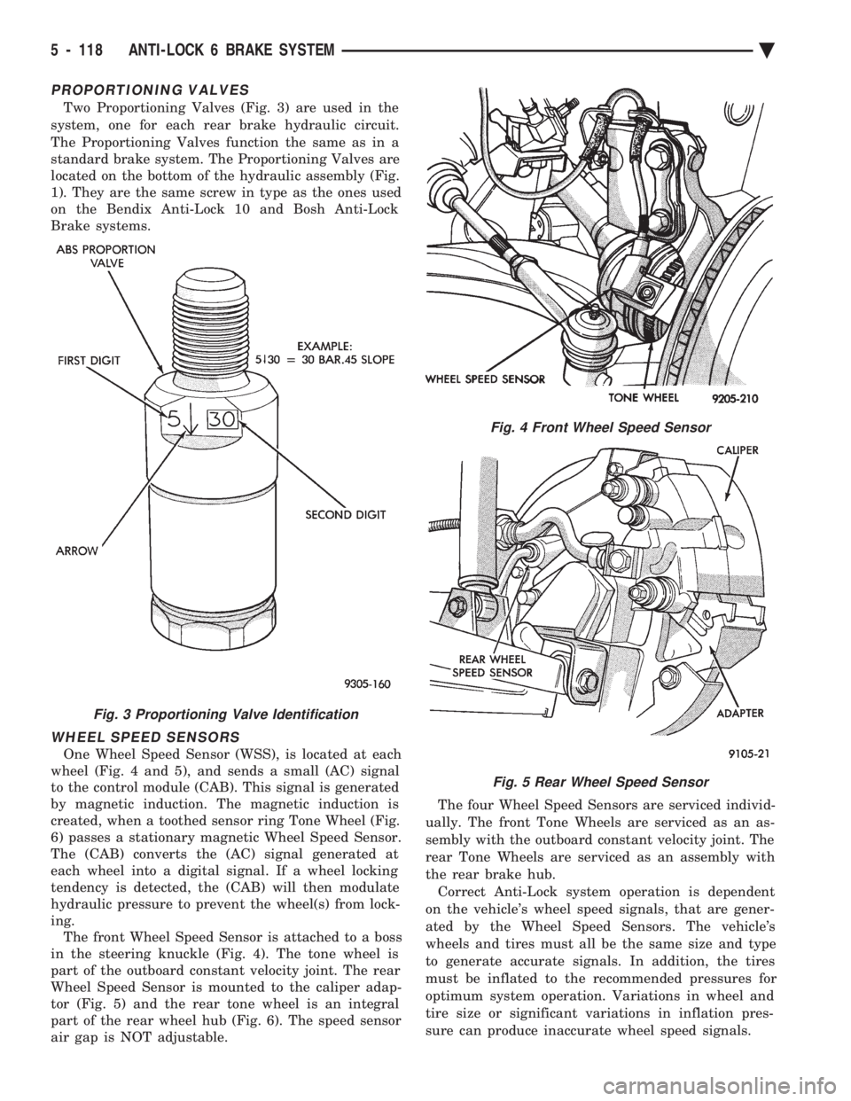
PROPORTIONING VALVES
Two Proportioning Valves (Fig. 3) are used in the
system, one for each rear brake hydraulic circuit.
The Proportioning Valves function the same as in a
standard brake system. The Proportioning Valves are
located on the bottom of the hydraulic assembly (Fig.
1). They are the same screw in type as the ones used
on the Bendix Anti-Lock 10 and Bosh Anti-Lock
Brake systems.
WHEEL SPEED SENSORS
One Wheel Speed Sensor (WSS), is located at each
wheel (Fig. 4 and 5), and sends a small (AC) signal
to the control module (CAB). This signal is generated
by magnetic induction. The magnetic induction is
created, when a toothed sensor ring Tone Wheel (Fig.
6) passes a stationary magnetic Wheel Speed Sensor.
The (CAB) converts the (AC) signal generated at
each wheel into a digital signal. If a wheel locking
tendency is detected, the (CAB) will then modulate
hydraulic pressure to prevent the wheel(s) from lock-
ing. The front Wheel Speed Sensor is attached to a boss
in the steering knuckle (Fig. 4). The tone wheel is
part of the outboard constant velocity joint. The rear
Wheel Speed Sensor is mounted to the caliper adap-
tor (Fig. 5) and the rear tone wheel is an integral
part of the rear wheel hub (Fig. 6). The speed sensor
air gap is NOT adjustable. The four Wheel Speed Sensors are serviced individ-
ually. The front Tone Wheels are serviced as an as-
sembly with the outboard constant velocity joint. The
rear Tone Wheels are serviced as an assembly with
the rear brake hub. Correct Anti-Lock system operation is dependent
on the vehicle's wheel speed signals, that are gener-
ated by the Wheel Speed Sensors. The vehicle's
wheels and tires must all be the same size and type
to generate accurate signals. In addition, the tires
must be inflated to the recommended pressures for
optimum system operation. Variations in wheel and
tire size or significant variations in inflation pres-
sure can produce inaccurate wheel speed signals.
Fig. 3 Proportioning Valve Identification
Fig. 4 Front Wheel Speed Sensor
Fig. 5 Rear Wheel Speed Sensor
5 - 118 ANTI-LOCK 6 BRAKE SYSTEM Ä
Page 304 of 2438
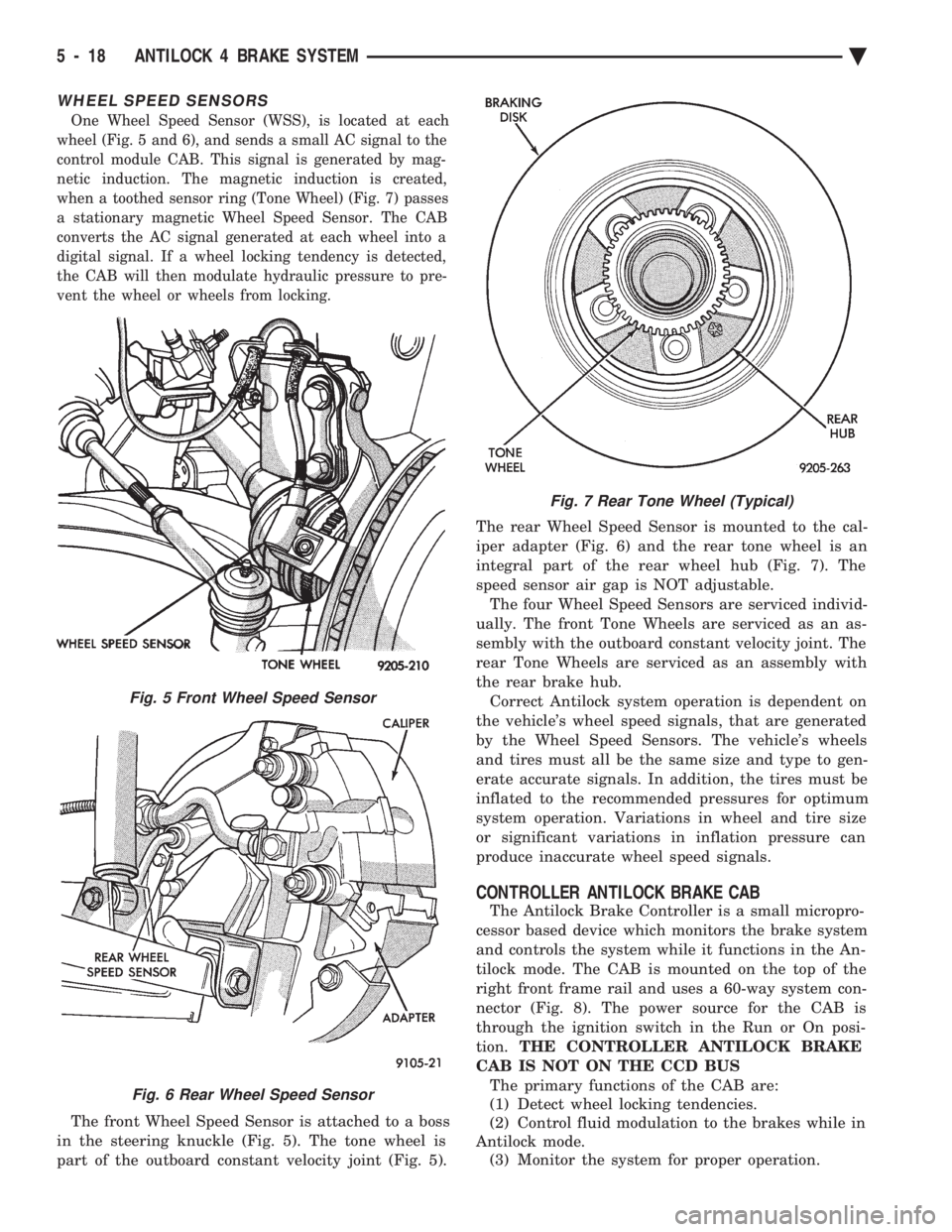
WHEEL SPEED SENSORS
One Wheel Speed Sensor (WSS), is located at each
wheel (Fig. 5 and 6), and sends a small AC signal to the
control module CAB. This signal is generated by mag-
netic induction. The magnetic induction is created,
when a toothed sensor ring (Tone Wheel) (Fig. 7) passes
a stationary magnetic Wheel Speed Sensor. The CAB
converts the AC signal generated at each wheel into a
digital signal. If a wheel locking tendency is detected,
the CAB will then modulate hydraulic pressure to pre-
vent the wheel or wheels from locking.
The front Wheel Speed Sensor is attached to a boss
in the steering knuckle (Fig. 5). The tone wheel is
part of the outboard constant velocity joint (Fig. 5). The rear Wheel Speed Sensor is mounted to the cal-
iper adapter (Fig. 6) and the rear tone wheel is an
integral part of the rear wheel hub (Fig. 7). The
speed sensor air gap is NOT adjustable.
The four Wheel Speed Sensors are serviced individ-
ually. The front Tone Wheels are serviced as an as-
sembly with the outboard constant velocity joint. The
rear Tone Wheels are serviced as an assembly with
the rear brake hub. Correct Antilock system operation is dependent on
the vehicle's wheel speed signals, that are generated
by the Wheel Speed Sensors. The vehicle's wheels
and tires must all be the same size and type to gen-
erate accurate signals. In addition, the tires must be
inflated to the recommended pressures for optimum
system operation. Variations in wheel and tire size
or significant variations in inflation pressure can
produce inaccurate wheel speed signals.
CONTROLLER ANTILOCK BRAKE CAB
The Antilock Brake Controller is a small micropro-
cessor based device which monitors the brake system
and controls the system while it functions in the An-
tilock mode. The CAB is mounted on the top of the
right front frame rail and uses a 60-way system con-
nector (Fig. 8). The power source for the CAB is
through the ignition switch in the Run or On posi-
tion. THE CONTROLLER ANTILOCK BRAKE
CAB IS NOT ON THE CCD BUS The primary functions of the CAB are:
(1) Detect wheel locking tendencies.
(2) Control fluid modulation to the brakes while in
Antilock mode. (3) Monitor the system for proper operation.
Fig. 5 Front Wheel Speed Sensor
Fig. 6 Rear Wheel Speed Sensor
Fig. 7 Rear Tone Wheel (Typical)
5 - 18 ANTILOCK 4 BRAKE SYSTEM Ä
Page 1952 of 2438
(16) Connect the battery ground (negative) cable.
Test the operation of the lights and horns. If applica-
ble, reset the clock and radio.
STEERING COLUMN COMPONENT SERVICE
The Acustar tilt and standard steering columns
(Fig.1) have been designed to be serviced as an as-
sembly; less wiring, switches, shrouds, steering
wheel, etc. Also most steering column components
can be serviced without removing the steering col-
umn from the vehicle. For additional information on
electrical components refer to Group 8H Electrical.
GEAR SHIFT LEVER
The gear shift lever (if equipped) is a serviceable
component of the Acustar steering column assembly.
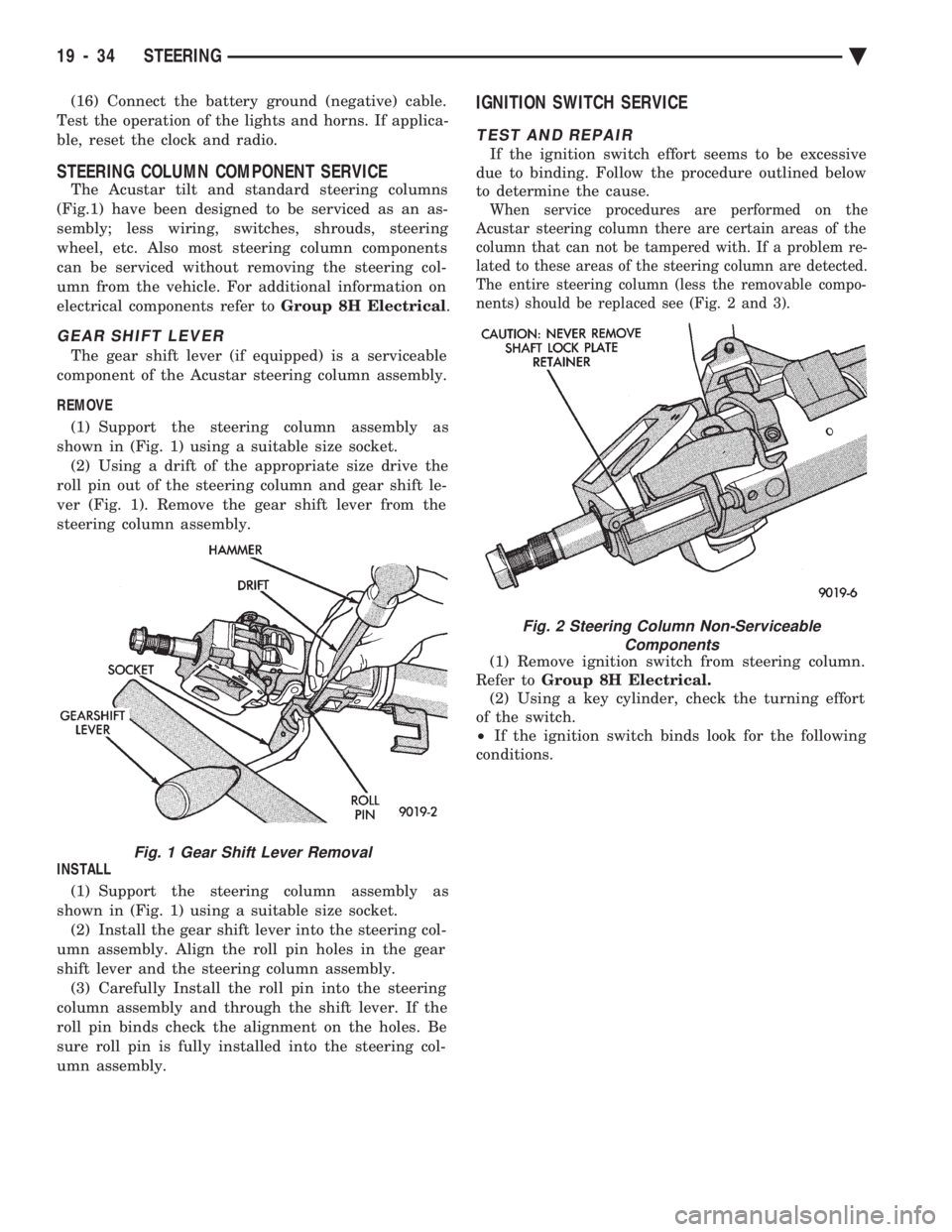
REMOVE (1) Support the steering column assembly as
shown in (Fig. 1) using a suitable size socket. (2) Using a drift of the appropriate size drive the
roll pin out of the steering column and gear shift le-
ver (Fig. 1). Remove the gear shift lever from the
steering column assembly.
INSTALL (1) Support the steering column assembly as
shown in (Fig. 1) using a suitable size socket. (2) Install the gear shift lever into the steering col-
umn assembly. Align the roll pin holes in the gear
shift lever and the steering column assembly. (3) Carefully Install the roll pin into the steering
column assembly and through the shift lever. If the
roll pin binds check the alignment on the holes. Be
sure roll pin is fully installed into the steering col-
umn assembly.
IGNITION SWITCH SERVICE
TEST AND REPAIR
If the ignition switch effort seems to be excessive
due to binding. Follow the procedure outlined below
to determine the cause.
When service procedures are performed on the
Acustar steering column there are certain areas of the
column that can not be tampered with. If a problem re-
lated to these areas of the steering column are detected.
The entire steering column (less the removable compo-
nents) should be replaced see (Fig. 2 and 3).
(1) Remove ignition switch from steering column.
Refer to Group 8H Electrical.
(2) Using a key cylinder, check the turning effort
of the switch.
² If the ignition switch binds look for the following
conditions.
Fig. 1 Gear Shift Lever Removal
Fig. 2 Steering Column Non-Serviceable Components
19 - 34 STEERING Ä
Page 2149 of 2438
WHEELSÐTIRES
CONTENTS
page page
SPECIFICATIONS ........................ 8
TIRE SERVICE PROCEDURES .............. 1 WHEELS SERVICE PROCEDURES
........... 6
TIRE SERVICE PROCEDURES INDEX
page page
Cleaning of Tires .......................... 1
General Information ........................ 1
Pressure Gauges ......................... 2
Radial-Ply Tires ........................... 1
Repairing Leaks .......................... 3
Rotation ................................ 3 Spare TireÐCompact
...................... 1
Tire Inflation Pressures ..................... 2
Tire Noise or Vibration ..................... 3
Tire Wear Patterns ........................ 3
Tread Wear Indicators ...................... 3
GENERAL INFORMATION
Throughout this group, references may be made to a
particular vehicle by letter or number designation. A
chart showing the breakdown of these designations is
included in the Introduction Section. Tires are designed for the vehicle and provide the
best overall performance for normal operation. The
ride and handling characteristics match the vehicle's
requirements. With proper care they will give excellent
reliability traction, skid resistance and tread life. They
have load carrying capacity, when properly inflated, to
operate at loads up to the specified Maximum Vehicle
Capacity. Driving habits have more effect on tire life than any
other factor. Careful drivers will obtain, in most cases,
much greater mileage than severe or careless drivers. A
few of the driving habits which will shorten the life of
any tire are:
² Rapid acceleration and deceleration
² Severe application of brakes
² High-speed driving
² Taking turns at excessive speeds
² Striking curbs and other obstacles
Radial ply tires can be more susceptible to irregular
tread wear. It is very important to follow the tire
rotation interval shown in the section on Tire
Rotation to achieve a greater tread life potential.
RADIAL-PLY TIRES
Radial-ply tires improve handling, tread life, and
ride quality and decrease rolling resistance. Radial-ply tires must always be used in sets of four
and under no circumstances should they be used on
the front only. However, they may be mixed with temporary spare tires when necessary,
but reduced speeds are recommended. Radial-ply tires have the same load carrying capac-
ity as other types of tires of the same size. They also
use the same recommended inflation pressures.
SPARE TIREÐCOMPACT
The compact spare tire is designed for emergency
use only. The original tire should be repaired and re-
installed at the first opportunity. Refer to Owner's
Manual for complete details.
TIRE CHAINS
Tire snow chains may be used on certainmodels.
Refer to Owner's Manual for more information.
CLEANING OF TIRES
Remove protective coating on tires before delivery
of vehicle, otherwise it could cause deterioration of
tires. Remove protective coating by applying warm wa-
ter, letting it soak one minute, and then scrubbing
the coating away with a soft bristle brush. Steam cleaning may also be used for cleaning.
DO NOT use gasoline or wire brush for cleaning.
DO NOT use mineral oil or an oil-based solvent.
Ä WHEELSÐTIRES 22 - 1