washer fluid CHEVROLET DYNASTY 1993 Service Manual
[x] Cancel search | Manufacturer: CHEVROLET, Model Year: 1993, Model line: DYNASTY, Model: CHEVROLET DYNASTY 1993Pages: 2438, PDF Size: 74.98 MB
Page 66 of 2438
INSPECTION
Inspect for evidence of fluid running from the up-
per end of the reservoir. (Actual leakage will be a
stream of fluid running down the side and dripping
off lower end of unit). A slight amount of seepage be-
tween the strut rod and strut shaft seal is not un-
usual and does not affect performance of the strut
assembly.
INSTALLATION
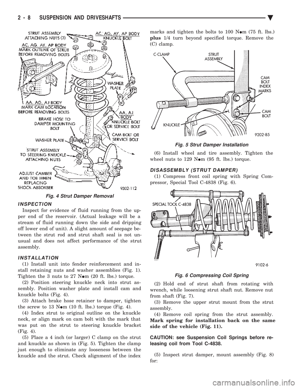
(1) Install unit into fender reinforcement and in-
stall retaining nuts and washer assemblies (Fig. 1).
Tighten the 3 nuts to 27 N Im (20 ft. lbs.) torque.
(2) Position steering knuckle neck into strut as-
sembly. Position washer plate and install cam and
knuckle bolts (Fig. 4). (3) Attach brake hose retainer to damper, tighten
the screw to 13 N Im (10 ft. lbs.) torque (Fig. 4).
(4) Index strut to original outline on the knuckle
neck, or align mark on cam bolt with the mark that
was put on the strut to steering knuckle bracket
(Fig. 4). (5) Plac e a 4 inch (or larger) C clamp on the strut
and knuckle as shown in (Fig. 5). Tighten the clamp
just enough to eliminate any looseness between the
knuckle and the strut. Check alignment of the index marks and tighten the bolts to 100 N
Im (75 ft. lbs.)
plus 1/4 turn beyond specified torque. Remove the
(C) clamp.
(6) Install wheel and tire assembly. Tighten the
wheel nuts to 129 N Im (95 ft. lbs.) torque.
DISASSEMBLY (STRUT DAMPER)
(1) Compress front coil spring with Spring Com-
pressor, Special Tool C-4838 (Fig. 6).
(2) Hold end of strut shaft from rotating with
wrench, while loosening strut shaft nut. Remove nut
from shaft (Fig. 7). (3) Remove the upper strut mount from the strut
assembly. (4) Remove coil spring from the strut assembly.
Mark spring for installation back on the same
side of the vehicle (Fig. 11).
CAUTION: see Suspension Coil Springs before re-
leasing coil from Tool C-4838.
(5) Inspect strut damper, mount assembly (Fig. 8)
for:
Fig. 4 Strut Damper Removal
Fig. 5 Strut Damper Installation
Fig. 6 Compressing Coil Spring
2 - 8 SUSPENSION AND DRIVESHAFTS Ä
Page 247 of 2438
(4) Remove the high and low pressure hose assem-
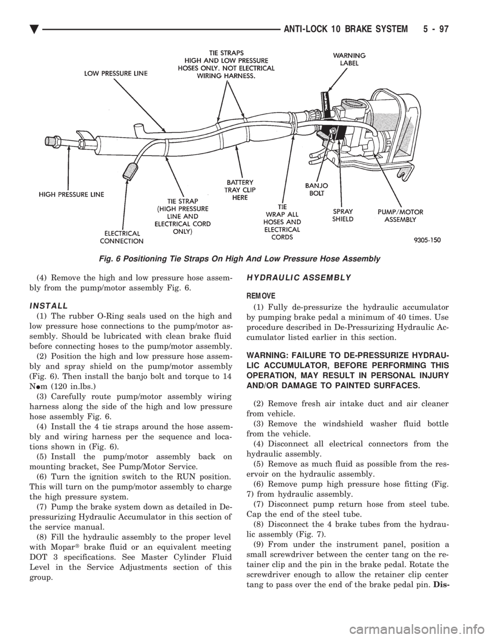
bly from the pump/motor assembly Fig. 6.
INSTALL
(1) The rubber O-Ring seals used on the high and
low pressure hose connections to the pump/motor as-
sembly. Should be lubricated with clean brake fluid
before connecting hoses to the pump/motor assembly. (2) Position the high and low pressure hose assem-
bly and spray shield on the pump/motor assembly
(Fig. 6). Then install the banjo bolt and torque to 14
N Im (120 in.lbs.)
(3) Carefully route pump/motor assembly wiring
harness along the side of the high and low pressure
hose assembly Fig. 6. (4) Install the 4 tie straps around the hose assem-
bly and wiring harness per the sequence and loca-
tions shown in (Fig. 6). (5) Install the pump/motor assembly back on
mounting bracket, See Pump/Motor Service. (6) Turn the ignition switch to the RUN position.
This will turn on the pump/motor assembly to charge
the high pressure system. (7) Pump the brake system down as detailed in De-
pressurizing Hydraulic Accumulator in this section of
the service manual. (8) Fill the hydraulic assembly to the proper level
with Mopar tbrake fluid or an equivalent meeting
DOT 3 specifications. See Master Cylinder Fluid
Level in the Service Adjustments section of this
group.
HYDRAULIC ASSEMBLY
REMOVE
(1) Fully de-pressurize the hydraulic accumulator
by pumping brake pedal a minimum of 40 times. Use
procedure described in De-Pressurizing Hydraulic Ac-
cumulator listed earlier in this section.
WARNING: FAILURE TO DE-PRESSURIZE HYDRAU-
LIC ACCUMULATOR, BEFORE PERFORMING THIS
OPERATION, MAY RESULT IN PERSONAL INJURY
AND/OR DAMAGE TO PAINTED SURFACES.
(2) Remove fresh air intake duct and air cleaner
from vehicle. (3) Remove the windshield washer fluid bottle
from the vehicle. (4) Disconnect all electrical connectors from the
hydraulic assembly. (5) Remove as much fluid as possible from the res-
ervoir on the hydraulic assembly. (6) Remove pump high pressure hose fitting (Fig.
7) from hydraulic assembly. (7) Disconnect pump return hose from steel tube.
Cap the end of the steel tube. (8) Disconnect the 4 brake tubes from the hydrau-
lic assembly (Fig. 7). (9) From under the instrument panel, position a
small screwdriver between the center tang on the re-
tainer clip and the pin in the brake pedal. Rotate the
screwdriver enough to allow the retainer clip center
tang to pass over the end of the brake pedal pin. Dis-
Fig. 6 Positioning Tie Straps On High And Low Pressure Hose Assembly
Ä ANTI-LOCK 10 BRAKE SYSTEM 5 - 97
Page 249 of 2438
(7) Install high pressure hose to hydraulic assem-
bly (Fig. 7). Tighten the hose, to hydraulic assembly
fitting to 16 N Im (145 in. lbs)
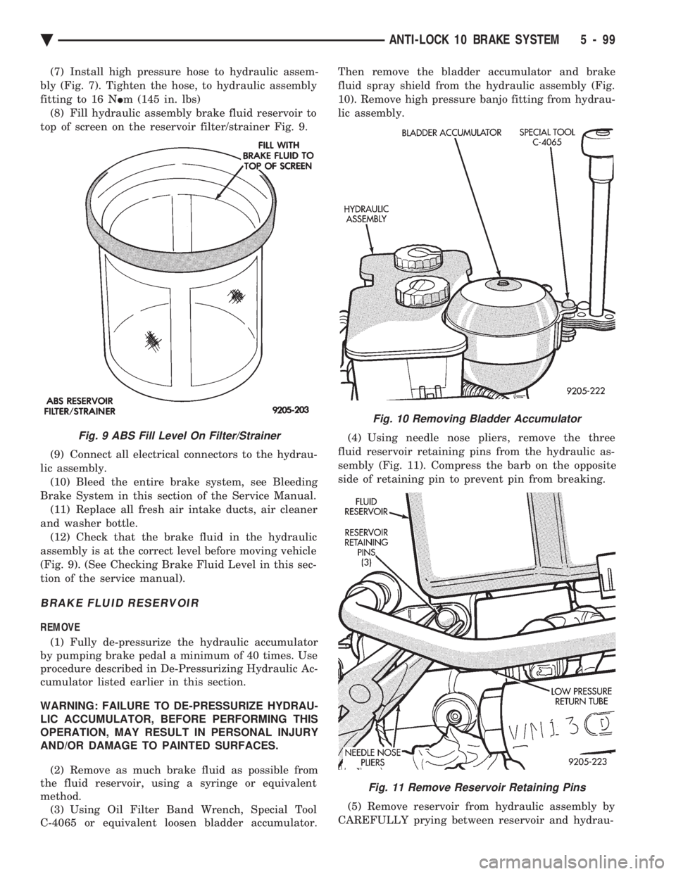
(8) Fill hydraulic assembly brake fluid reservoir to
top of screen on the reservoir filter/strainer Fig. 9.
(9) Connect all electrical connectors to the hydrau-
lic assembly. (10) Bleed the entire brake system, see Bleeding
Brake System in this section of the Service Manual. (11) Replace all fresh air intake ducts, air cleaner
and washer bottle. (12) Check that the brake fluid in the hydraulic
assembly is at the correct level before moving vehicle
(Fig. 9). (See Checking Brake Fluid Level in this sec-
tion of the service manual).
BRAKE FLUID RESERVOIR
REMOVE
(1) Fully de-pressurize the hydraulic accumulator
by pumping brake pedal a minimum of 40 times. Use
procedure described in De-Pressurizing Hydraulic Ac-
cumulator listed earlier in this section.
WARNING: FAILURE TO DE-PRESSURIZE HYDRAU-
LIC ACCUMULATOR, BEFORE PERFORMING THIS
OPERATION, MAY RESULT IN PERSONAL INJURY
AND/OR DAMAGE TO PAINTED SURFACES.
(2) Remove as much brake fluid as possible from
the fluid reservoir, using a syringe or equivalent
method. (3) Using Oil Filter Band Wrench, Special Tool
C-4065 or equivalent loosen bladder accumulator. Then remove the bladder accumulator and brake
fluid spray shield from the hydraulic assembly (Fig.
10). Remove high pressure banjo fitting from hydrau-
lic assembly.
(4) Using needle nose pliers, remove the three
fluid reservoir retaining pins from the hydraulic as-
sembly (Fig. 11). Compress the barb on the opposite
side of retaining pin to prevent pin from breaking.
(5) Remove reservoir from hydraulic assembly by
CAREFULLY prying between reservoir and hydrau-
Fig. 9 ABS Fill Level On Filter/Strainer
Fig. 10 Removing Bladder Accumulator
Fig. 11 Remove Reservoir Retaining Pins
Ä ANTI-LOCK 10 BRAKE SYSTEM 5 - 99
Page 424 of 2438
VISUAL MESSAGES
Following are the visual messages and the condi-
tions under which, the messages will be given:
² Keys in ignition
² Exterior lamps on
These messages will appear if the conditions are
present and the driver's door is open while the igni-
tion switch is in the OFF, LOCK, or ACC positions.
A tone will sound until the condition is corrected or
the door is closed.
² Passenger door ajar
² Driver door ajar
² Trunk ajar
² Park brake engaged
² Right rear door ajar
² Left rear door ajar
These messages will appear if a condition is de-
tected after the vehicle is in motion. When the con-
dition is corrected, a short tone will sound to
acknowledge the action. LOW OIL PRESSURE
If this message is displayed while the vehicle is at
cruising speeds, immediate attention is required. If
this message appears at idle speed, increase the idle
speed and the message should go off. If the message
remains on, immediate attention is required. ENGINE TEMP CRITICAL
This message appears when a sensor has determined
that the engine coolant is overheating. If this message
comes on and stays on, immediate action is required.
COOLANT LEVEL LOW
LOW FUEL LEVEL
LOW BRAKE FLUID
WASHER FLUID LOW
These messages will appear if a continuous warn-
ing condition is detected while the engine is running.
Inspection is required. To clear this message from
the display, after the condition is corrected, the igni-
tion switch must be turned OFF. CHECK TRANS
This message will appear if a continuous warning
condition is detected while the engine is running. Im-
mediate attention is recommended. To clear this mes-
sage from the display, after the condition has been
corrected, the ignition switch must be turned OFF. VOLTAGE IMPROPER
This message will appear if a continuous warning
condition is detected. Immediate attention is re-
quired. To clear this message from the display, after
the condition has been corrected, the ignition switch
must be turned OFF. TURN SIGNAL ON
This message will appear if the turn signal is left
on while vehicle speed is over 15 mph and the vehi-
cle has traveled over one-half mile. FASTEN SEAT BELTS An intermittent chime tone will sound for several
seconds if the seat belt is not fastened. CHK ENGINE OIL LEVEL
If this message is delivered, a check of the engine
oil dipstick is suggested. To clear this message, after
the condition is corrected, the ignition switch must
be turned OFF. HEADLAMP OUT
BRAKE LAMP OUT
TAIL LAMP OUT
These conditions are monitored only when the lamps
are on. The message will remain, even after the lamp is
replaced, until the lamp is turned on and operates.
SERVICE REMINDER
The maintenance reminder statement is programmed
to provide general information only. Refer to Group 0,
Lubrication & Maintenance for specific vehicle require-
ments.
The service reminder message is displayed at 7,500
miles or 12 months intervals, which ever comes first. MONITORED SYSTEMS OK
If there is no warning condition to report, the mes-
sage Monitored Systems OK is displayed (Fig. 2).
AUTOMATIC CALIBRATION SET PROCEDURE
The engine compartment node will continuously
and automatically recalibrate the compass under nor-
mal driving conditions. As long as the vehicle is
turning, the engine compartment node will record
new compass data. This new data will be used to
recalibrate the compass at a rate of at least once per
full (360 degree) turn of the vehicle. Automatic cali-
bration does not require operator interface.
MANUAL CALIBRATION SET PROCEDURE
Manual compass calibration has been replaced by
automatic calibration set procedure. The manual cal-
ibration set procedure is available, but no longer
serves any useful purpose.
EVIC SELF CHECK DIAGNOSTICS
Ignition switch ON, the EVIC not displaying any
message, may imply a system failure and not an
EVIC failure. Turn the ignition OFF, close all vehi-
cle doors and wait at least 60 seconds before begin-
ning test. Turn ignition switch to the ON position.
Pressing the TEMP, FUEL and INFO buttons at the
same time shall provide the visual message MOD-
ULE SELF CHECK for two seconds. Following at
two second interval there will be messages:
² E2-0 SELF CHECK
² E3-0 SELF CHECK
² END OF SELF CHECK
Showing the microcomputer is working properly.
When the self check mode and message shows:
² E2-1
² E3-2
This would show a fault exists in the EVIC's micro-
computer and the EVIC should be replaced (Fig. 3).
8C - 8 OVERHEAD CONSOLE Ä
Page 431 of 2438
VISUAL MESSAGES
Following are the visual messages and the condi-
tions under which, the messages will be given:
² Keys in ignition
² Exterior lamps on
These messages will appear if the conditions are
present and the driver's door is open while the igni-
tion switch is in the OFF, LOCK, or ACC positions.
A tone will sound until the condition is corrected or
the door is closed.
² Passenger door ajar
² Driver door ajar
² Trunk ajar
² Park brake engaged
² Right rear door ajar
² Left rear door ajar
These messages will appear if a condition is de-
tected after the vehicle is in motion. When the con-
dition is corrected, a short tone will sound to
acknowledge the action. LOW OIL PRESSURE
If this message is displayed while the vehicle is at
cruising speeds, immediate attention is required. If
this message appears at idle speed, increase the idle
speed and the message should go off. If the message
remains on, immediate attention is required. ENGINE TEMP CRITICAL
This message appears when a sensor has deter-
mined that the engine coolant is overheating. If this
message comes on and stays on, immediate action is
required. COOLANT LEVEL LOW
LOW FUEL LEVEL
LOW BRAKE FLUID WASHER FLUID LOW
These messages will appear if a continuous warn-
ing condition is detected while the engine is running.
Inspection is required. To clear this message from
the display, after the condition is corrected, the igni-
tion switch must be turned OFF. CHECK TRANS
This message will appear if a continuous warning
condition is detected while the engine is running. Im-
mediate attention is recommended. To clear this mes-
sage from the display, after the condition has been
corrected, the ignition switch must be turned OFF. VOLTAGE IMPROPER
This message will appear if a continuous warning
condition is detected. Immediate attention is re-
quired. To clear this message from the display, after
the condition has been corrected, the ignition switch
must be turned OFF. TURN SIGNAL ON
This message will appear if the turn signal is left
on while vehicle speed is over 15 mph and the vehi-
cle has traveled over one-half mile. FASTEN SEAT BELTS
An intermittent chime tone will sound for several
seconds if the seat belt is not fastened. CHK ENGINE OIL LEVEL
If this message is delivered, a check of the engine
oil dipstick is suggested. To clear this message, after
the condition is corrected, the ignition switch must
be turned OFF. HEADLAMP OUT
BRAKE LAMP OUT
TAIL LAMP OUT
These conditions are monitored only when the
lamps are on. The message will remain, even after
the lamp is replaced, until the lamp is turned on and
operates. SERVICE REMINDER
The maintenance reminder statement is pro-
grammed to provide general information only. Refer
to Group 0, Lubrication & Maintenance for specific
vehicle requirements. The service reminder message is displayed at 7,500
miles or 12 months intervals, which ever comes first. MONITORED SYSTEMS OK
If there is no warning condition to report, the mes-
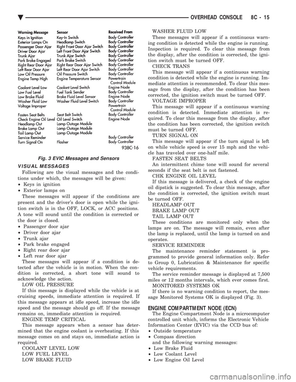
sage Monitored Systems OK is displayed (Fig. 3).
ENGINE COMPARTMENT NODE (ECN)
The Engine Compartment Node is a microcomputer
controlled unit which, informs the Electronic Vehicle
Information Center (EVIC) via the CCD bus of:
² Outside temperature
² Compass direction
and the following warning messages:
² Low Brake Fluid
² Low Coolant Level
² Low Engine Oil Level
Fig. 3 EVIC Messages and Sensors
Ä OVERHEAD CONSOLE 8C - 15
Page 494 of 2438
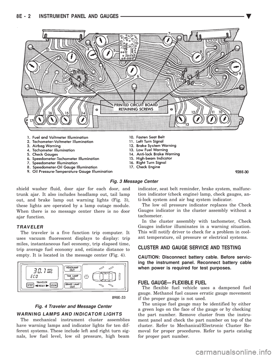
shield washer fluid, door ajar for each door, and
trunk ajar. It also includes headlamp out, tail lamp
out, and brake lamp out warning lights (Fig. 3),
these lights are operated by a lamp outage module.
When there is no message center there is no door
ajar function.
TRAVELER
The traveler is a five function trip computer. It
uses vacuum fluorescent displays to display: trip
miles, instantaneous fuel economy, trip elapsed time,
trip average fuel economy and, estimate distance to
empty. It is located in the message center (Fig. 4).
WARNING LAMPS AND INDICATOR LIGHTS
The mechanical instrument cluster assemblies
have warning lamps and indicator lights for ten dif-
ferent systems. These include left and right turn sig-
nals, low fuel level, low oil pressure, high beam indicator, seat belt reminder, brake system, malfunc-
tion indicator (check engine) lamp, check gauges, an-
ti-lock system and air bag system indicator. The low oil pressure indicator replaces the Check
Gauges indicator in the cluster assembly without a
tachometer. In the cluster assembly with tachometer, Check
Gauges indictor illuminates in a warning situation.
This will notify driver to check for a problem in cool-
ant temperature, oil pressure or electrical systems.
CLUSTER AND GAUGE SERVICE AND TESTING
CAUTION: Disconnect battery cable. Before servic-
ing the instrument panel. Reconnect battery cable
when power is required for test purposes.
FUEL GAUGEÐFLEXIBLE FUEL
The flexible fuel vehicle uses a dampened fuel
gauge. Methanol fuel causes erratic gauge movement
if the proper gauge is not used. The unique fuel gauge may be identified by either
a green logo on the face of the gauge or by checking
the part number. Remove cluster from the instru-
ment panel and check the part number on top of the
cluster. Refer to Mechanical/Electronic Cluster Re-
moval for proper procedures. Refer to parts catalog
for proper part number.
Fig. 3 Message Center
Fig. 4 Traveler and Message Center
8E - 2 INSTRUMENT PANEL AND GAUGES Ä
Page 515 of 2438
AC AND AY BODIES INDEX
page page
Electronic Cluster ........................ 34
Gauges ................................ 28
General Information ....................... 23
Interior Lamp Replacement ................. 41 Mechanical Cluster and Gauge Service
........ 24
Mechanical/Electronic Cluster Removal ........ 25
Switch and Panel Component Service ......... 37
GENERAL INFORMATION
MECHANICAL CLUSTER
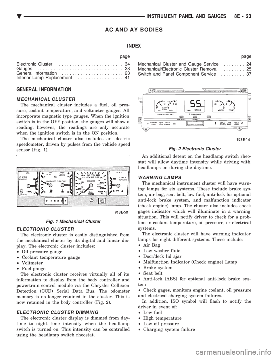
The mechanical cluster includes a fuel, oil pres-
sure, coolant temperature, and voltmeter gauges. All
incorporate magnetic type gauges. When the ignition
switch is in the OFF position, the gauges will show a
reading; however, the readings are only accurate
when the ignition switch is in the ON position. The mechanical cluster also includes an electric
speedometer, driven by pulses from the vehicle speed
sensor (Fig. 1).
ELECTRONIC CLUSTER
The electronic cluster is easily distinguished from
the mechanical cluster by its digital and linear dis-
play. The electronic cluster includes:
² Oil pressure gauge
² Coolant temperature gauge
² Voltmeter
² Fuel gauge
The electronic cluster receives virtually all of its
information to display from the body controller and
powertrain control module via the Chrysler Collision
Detection (CCD) Serial Data Bus. The odometer
memory is no longer retained in the cluster. This is
now retained in the body controller (Fig. 2).
ELECTRONIC CLUSTER DIMMING
The electronic cluster display is dimmed from day-
time to night time intensity when the headlamp
switch is turned on. This intensity can be controlled
using the headlamp switch rheostat. An additional detent on the headlamp switch rheo-
stat will allow daytime intensity while driving with
headlamps on during the daytime.
WARNING LAMPS
The mechanical instrument cluster will have warn-
ing lamps for six systems. These include brake sys-
tem, air bag, seat belt, low fuel, anti-lock for optional
anti-lock brake system, and malfunction indicator
(check engine) lamp. The cluster also includes check
gages indicator which will illuminate in a warning
situation. This will notify driver to check for a prob-
lem in coolant temperature, oil pressure, or electrical
systems. The electronic cluster will have warning indicator
lamps for eight different systems. These include:
² Air Bag
² Low washer fluid
² Door/deck lid ajar
² Malfunction Indicator (Check engine) Lamp
² Brake system
² Seat belt
² Anti-lock (ABS) for optional anti-lock brake sys-
tem
² Check gages, monitors engine coolant, oil pressure
and electrical charging system failures. In addition, ISO symbol will flash to notify the
driver in event of:
² Low fuel
² High temperature
² Low oil pressure
² Charging system failure
Fig. 1 Mechanical Cluster
Fig. 2 Electronic Cluster
Ä INSTRUMENT PANEL AND GAUGES 8E - 23
Page 526 of 2438
ELECTRONIC CLUSTER
SELF DIAGNOSTIC SYSTEM
The electronic clusters have an internal diagnostics
routing to isolate problems within the cluster or CCD
Bus. Using the cluster Self-Diagnostic Test will deter-
mine whether the problem is within the cluster or
outside of cluster (Fig. 29 and 30). Successful completion of the Self Diagnostic Test
indicates that the problem is in the CCD Bus, inter-
facing modules, connectors, or sensors outside of the
cluster. Refer to Fig. 31 for terminal listing.
CONDITION: CLUSTER DISPLAYS DO NOT ILLUMINATE AFTER VEHICLE IS STARTED
PROCEDURE
(1) Check fuses and verify battery and ignition
voltage at cluster connector. (2) Check ground from cluster connector to instru-
ment panel ground stud.
CONDITION: CLUSTER ASTERISK (*) FLASHES, CLUSTER DISPLAYS NOTINDICATING CORRECT DATA.
PROCEDURE
CCD bus problem. Use the Body Chassis Diagnos-
tic Manual to diagnose CCD Bus.
CONDITION: SPEEDOMETER AND ODOMETER ARE INOPERATIVE OR OPERATESINTERMITTENTLY
PROCEDURE
(1) If speedometer reads 0, or odometer is blank,
and cluster asterisk is flashing, use the Body Chassis
Diagnostic Manual to diagnose CCD Bus problem. (2) If cluster asterisk is not flashing, check for de-
fective vehicle speed sensor or speed sensor wiring.
CONDITION: OIL GAUGE, FUEL GAUGE, TEMPERATURE GAUGE, OR VOLTAGE GAUGEINOPERATIVE
PROCEDURE
If any gauge gives no indication and cluster aster-
isk is flashing, use the Body Chassis Manual to diag-
nose CCD Bus problem. If cluster asterisk is not flashing:
(1) Check for defective sending unit or wiring. (a) Sending units and wiring can be checked by
grounding the connector leads, at the sending unit,
in the vehicle. (b) With the ignition in the ON position, a
grounded input will cause the oil, fuel, or temper-
ature gauge to read maximum. (2) If the problem is with the oil, temperature, or
fuel gauge, check the body controller. If the problem
is with the voltage gauge, check the powertrain con-
trol module operation.
CONDITION: CLUSTER DISPLAY DOES NOT DIM WHEN HEADLAMP SWITCH ISACTIVATED AND RHEOSTAT ROTATED
PROCEDURE
If the cluster asterisk is flashing, Refer to the Body
Chassis Diagnostic Manual to diagnose the CCD Bus. If the cluster asterisk is not flashing:
(1) Check fuses in headlamp circuit.
(2) Check for loose connections or defective wiring
for headlamp switch to body controller. (3) Check for defective headlamp switch. The elec-
tronic instrument cluster receives the display inten-
sity status from the body controller via the CCD Bus.
CONDITION: SEAT BELT WARNING LAMP DOES NOT ILLUMINATE
PROCEDURE
Turn on ignition. Lamp should illuminate for six
seconds. If not: (1) Check for burned out lamp and retest.
(2) Replace cluster.
CONDITION: LOW WASHER, DOOR/DECK, OR MALFUNCTION INDICATOR (CHECK ENGINE)LAMP, DO NOT ILLUMINATE
PROCEDURE
(1) Perform cluster self-diagnostics to determine if
lamp will illuminate. If lamp does not, check for
burned out lamp, replace and retest. (2) If cluster asterisk is flashing, Refer to the Body
Chassis Diagnostic Manual to diagnose CCD Bus. (3) If cluster asterisk is not flashing:(a) For low washer fluid or door/deck, check in-
puts to body controller. (b) For malfunction indicator (check engine),
check powertrain control module operation.
CONDITION: ODOMETER DISPLAY IS BLANK. THE ODOMETER VALUE IS NO LONGERRETAINED IN THIS ELECTRONIC CLUSTER.THIS TAKES PLACE IN THE BODYCONTROLLER
PROCEDURE
(1) If cluster asterisk is flashing, Refer to the Body
Chassis Diagnostic Manual to diagnose CCD Bus. (2) If cluster asterisk is not flashing, perform clus-
ter self-diagnostics. If code 921 appears in the odom-
eter display, replace body controller for odometer
failure.
8E - 34 INSTRUMENT PANEL AND GAUGES Ä
Page 534 of 2438
AG AND AJ BODIES INDEX
page page
Cigar Lighter Removal ..................... 55
Cluster and Gauge Service and Testing ....... 43
Electronic Cluster ........................ 50
Electronic Vehicle Information Center (EVIC) .... 42
Engine Compartment Node ................. 55
Gauges ................................ 44 General Information
....................... 42
Instrument Panel Roll Down Procedure ........ 56
Interior Lamp Removal .................... 57
Mechanical/Electronic Cluster Removal ........ 43
Switch and Panel Component Service ......... 51
Switch Pod Assembly Removal .............. 43
GENERAL INFORMATION
CONVENTIONAL INSTRUMENT CLUSTER
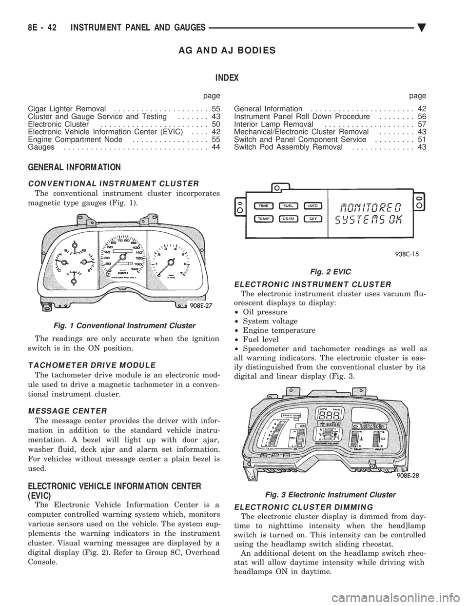
The conventional instrument cluster incorporates
magnetic type gauges (Fig. 1).
The readings are only accurate when the ignition
switch is in the ON position.
TACHOMETER DRIVE MODULE
The tachometer drive module is an electronic mod-
ule used to drive a magnetic tachometer in a conven-
tional instrument cluster.
MESSAGE CENTER
The message center provides the driver with infor-
mation in addition to the standard vehicle instru-
mentation. A bezel will light up with door ajar,
washer fluid, deck ajar and alarm set information.
For vehicles without message center a plain bezel is
used.
ELECTRONIC VEHICLE INFORMATION CENTER
(EVIC)
The Electronic Vehicle Information Center is a
computer controlled warning system which, monitors
various sensors used on the vehicle. The system sup-
plements the warning indicators in the instrument
cluster. Visual warning messages are displayed by a
digital display (Fig. 2). Refer to Group 8C, Overhead
Console.
ELECTRONIC INSTRUMENT CLUSTER
The electronic instrument cluster uses vacuum flu-
orescent displays to display:
² Oil pressure
² System voltage
² Engine temperature
² Fuel level
² Speedometer and tachometer readings as well as
all warning indicators. The electronic cluster is eas-
ily distinguished from the conventional cluster by its
digital and linear display (Fig. 3.
ELECTRONIC CLUSTER DIMMING
The electronic cluster display is dimmed from day-
time to nighttime intensity when the head]lamp
switch is turned on. This intensity can be controlled
using the headlamp switch sliding rheostat. An additional detent on the headlamp switch rheo-
stat will allow daytime intensity while driving with
headlamps ON in daytime.
Fig. 1 Conventional Instrument Cluster
Fig. 2 EVIC
Fig. 3 Electronic Instrument Cluster
8E - 42 INSTRUMENT PANEL AND GAUGES Ä
Page 637 of 2438
WINDSHIELD WASHERS INDEX
page page
General Information ....................... 17
Washer Nozzle .......................... 19 Washer Reservoir Pump
................... 18
Washer Reservoirs ....................... 17
GENERAL INFORMATION
All models are equipped with electric operated
windshield washer pumps. The wash function can be accessed in the OFF po-
sition of the wiper control switch. Holding the wash
button depressed when the switch is in the OFF po-
sition will operate the wipers and washer motor
pump continuously until the washer button is re-
leased. Releasing the button will stop the washer
pump but the wipers will complete the current wipe
cycle. Then followed by an average of two more wipe
cycles ( 61) before the wipers park and the module
turns off. Whenever a windshield washer malfunction occurs,
first verify that the windshield washer wire harness
is properly connected to all connectors before starting
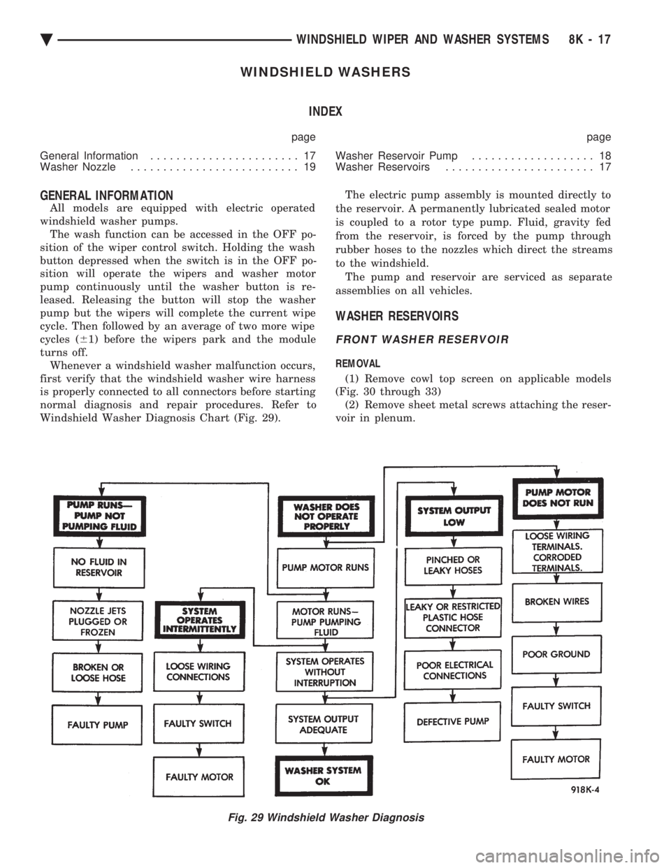
normal diagnosis and repair procedures. Refer to
Windshield Washer Diagnosis Chart (Fig. 29). The electric pump assembly is mounted directly to
the reservoir. A permanently lubricated sealed motor
is coupled to a rotor type pump. Fluid, gravity fed
from the reservoir, is forced by the pump through
rubber hoses to the nozzles which direct the streams
to the windshield. The pump and reservoir are serviced as separate
assemblies on all vehicles.
WASHER RESERVOIRS
FRONT WASHER RESERVOIR
REMOVAL
(1) Remove cowl top screen on applicable models
(Fig. 30 through 33) (2) Remove sheet metal screws attaching the reser-
voir in plenum.
Fig. 29 Windshield Washer Diagnosis
Ä WINDSHIELD WIPER AND WASHER SYSTEMS 8K - 17