CHEVROLET IMPALA 2007 9.G Owners Manual
Manufacturer: CHEVROLET, Model Year: 2007, Model line: IMPALA, Model: CHEVROLET IMPALA 2007 9.GPages: 460, PDF Size: 2.56 MB
Page 341 of 460
{CAUTION:
Fans or other moving engine parts can
injure you badly. Keep your hands away
from moving parts once the engine is
running.
5. Check that the jumper cables do not have
loose or missing insulation. If they do, you
could get a shock. The vehicles could
be damaged too.
Before you connect the cables, here are some
basic things you should know. Positive (+)
will go to positive (+) or to a remote
positive (+) terminal if the vehicle has one.
Negative (−) will go to a heavy, unpainted
metal engine part or to a remote negative (−)
terminal if the vehicle has one.
Do not connect positive (+) to negative (−),
or you will get a short that would damage the
battery and maybe other parts too. And do
not connect the negative (−) cable to the
negative (−) terminal on the dead battery
because this can cause sparks.6. Connect the red positive (+) cable to the
positive (+) terminal location of the vehicle
with the dead battery. Use a remote
positive (+) terminal if the vehicle has one.
7. Do not let the other end touch metal. Connect
it to the positive (+) terminal location of the
vehicle with the good battery. Use a remote
positive (+) terminal if the vehicle has one.
8. Now connect the black negative (−) cable
to the negative (−) terminal location of the
vehicle with the good battery. Use a remote
negative (−) terminal if the vehicle has one.
Do not let the other end touch anything until the
next step. The other end of the negative (−)
cable does not go to the dead battery. It goes
to a heavy, unpainted metal engine part or to a
remote negative (−) terminal on the vehicle with
the dead battery.
341
Page 342 of 460
9. Connect the other end of the negative (−) cable
at least 18 inches (45 cm) away from the dead
battery, but not near engine parts that move.
The electrical connection is just as good there,
and the chance of sparks getting back to the
battery is much less.
10. Now start the vehicle with the good battery
and run the engine for a while.
11. Try to start the vehicle that had the dead
battery. If it will not start after a few tries,
it probably needs service.
Notice:If the jumper cables are connected
or removed in the wrong order, electrical
shorting may occur and damage the vehicle.
The repairs would not be covered by your
warranty. Always connect and remove
the jumper cables in the correct order, making
sure that the cables do not touch each other
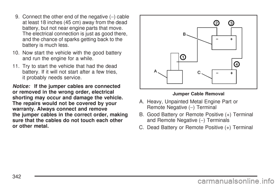
or other metal.A. Heavy, Unpainted Metal Engine Part or
Remote Negative (−) Terminal
B. Good Battery or Remote Positive (+) Terminal
and Remote Negative (−) Terminals
C. Dead Battery or Remote Positive (+) Terminal
Jumper Cable Removal
342
Page 343 of 460
To disconnect the jumper cables from both
vehicles, do the following:
1. Disconnect the black negative (−) cable from
the vehicle that had the dead battery.
2. Disconnect the black negative (−) cable from
the vehicle with the good battery.
3. Disconnect the red positive (+) cable from the
vehicle with the good battery.
4. Disconnect the red positive (+) cable from the
other vehicle.
5. Return the fuse block cover to its original
position.Headlamp Aiming
Headlamp aim has been preset at the factory and
should need no further adjustment.
However, if your vehicle is damaged in an accident,
the headlamp aim may be affected. Aim adjustment
to the low-beam headlamps may be necessary if it
is difficult to see the lane markers (for horizontal
aim), or if oncoming drivers �ash their high-beam
headlamps at you (for vertical aim).
If you believe your headlamps need to be
re-aimed, it is recommend that you take the vehicle
to your dealer for service.
Bulb Replacement
For the proper type of replacement bulbs,
seeReplacement Bulbs on page 349.
For any bulb changing procedure not listed in this
section, contact your dealer.
343
Page 344 of 460
Halogen Bulbs
{CAUTION:
Halogen bulbs have pressurized gas
inside and can burst if you drop or
scratch the bulb. You or others could be
injured. Be sure to read and follow the
instructions on the bulb package.
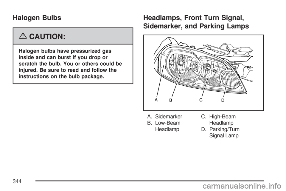
Headlamps, Front Turn Signal,
Sidemarker, and Parking Lamps
A. Sidemarker
B. Low-Beam
HeadlampC. High-Beam
Headlamp
D. Parking/Turn
Signal Lamp
344
Page 345 of 460
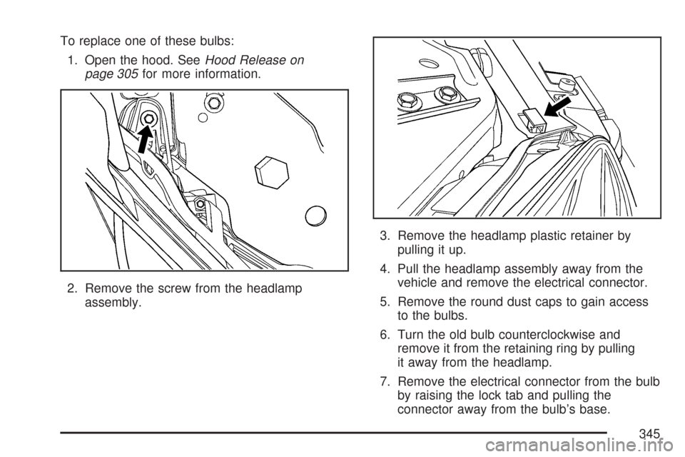
To replace one of these bulbs:
1. Open the hood. SeeHood Release on
page 305for more information.
2. Remove the screw from the headlamp
assembly.3. Remove the headlamp plastic retainer by
pulling it up.
4. Pull the headlamp assembly away from the
vehicle and remove the electrical connector.
5. Remove the round dust caps to gain access
to the bulbs.
6. Turn the old bulb counterclockwise and
remove it from the retaining ring by pulling
it away from the headlamp.
7. Remove the electrical connector from the bulb
by raising the lock tab and pulling the
connector away from the bulb’s base.
345
Page 346 of 460
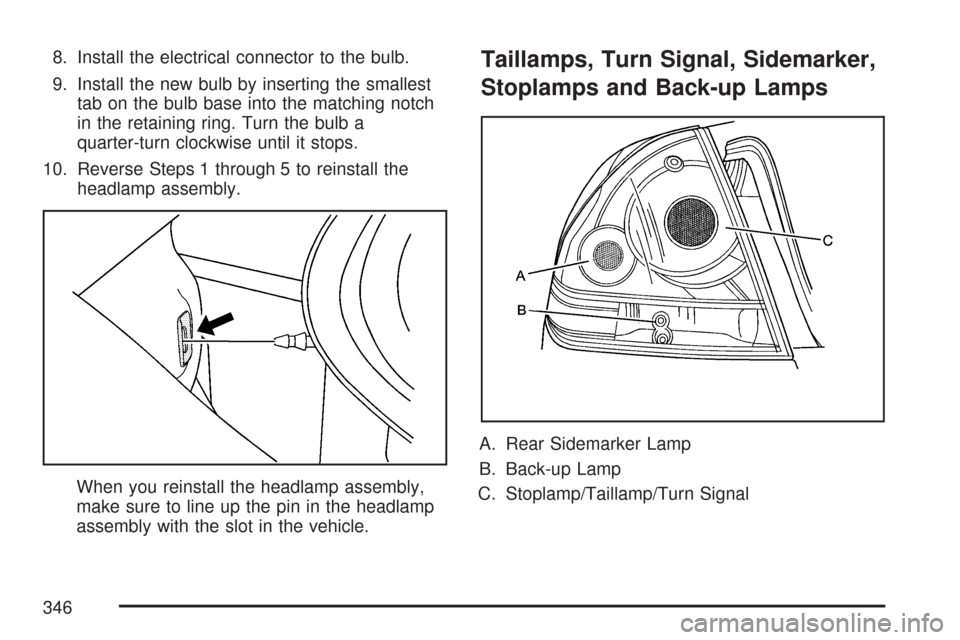
8. Install the electrical connector to the bulb.
9. Install the new bulb by inserting the smallest
tab on the bulb base into the matching notch
in the retaining ring. Turn the bulb a
quarter-turn clockwise until it stops.
10. Reverse Steps 1 through 5 to reinstall the
headlamp assembly.
When you reinstall the headlamp assembly,
make sure to line up the pin in the headlamp
assembly with the slot in the vehicle.Taillamps, Turn Signal, Sidemarker,
Stoplamps and Back-up Lamps
A. Rear Sidemarker Lamp
B. Back-up Lamp
C. Stoplamp/Taillamp/Turn Signal
346
Page 347 of 460
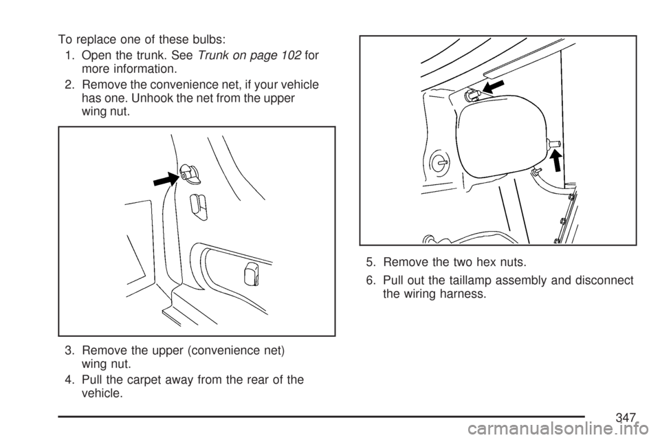
To replace one of these bulbs:
1. Open the trunk. SeeTrunk on page 102for
more information.
2. Remove the convenience net, if your vehicle
has one. Unhook the net from the upper
wing nut.
3. Remove the upper (convenience net)
wing nut.
4. Pull the carpet away from the rear of the
vehicle.5. Remove the two hex nuts.
6. Pull out the taillamp assembly and disconnect
the wiring harness.
347
Page 348 of 460
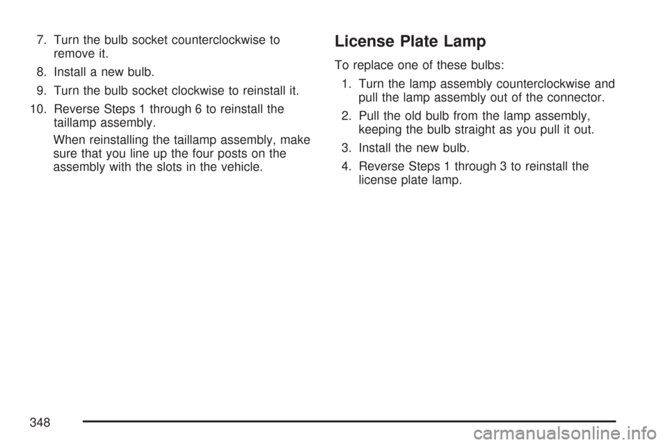
7. Turn the bulb socket counterclockwise to
remove it.
8. Install a new bulb.
9. Turn the bulb socket clockwise to reinstall it.
10. Reverse Steps 1 through 6 to reinstall the
taillamp assembly.
When reinstalling the taillamp assembly, make
sure that you line up the four posts on the
assembly with the slots in the vehicle.License Plate Lamp
To replace one of these bulbs:
1. Turn the lamp assembly counterclockwise and
pull the lamp assembly out of the connector.
2. Pull the old bulb from the lamp assembly,
keeping the bulb straight as you pull it out.
3. Install the new bulb.
4. Reverse Steps 1 through 3 to reinstall the
license plate lamp.
348
Page 349 of 460
Replacement Bulbs
Exterior Lamp Bulb Number
Back-Up 921
Front Parking/Turn Signal 3157NAK
License Plate Lamp 194
Headlamps
High-Beam H9
Low-Beam H11
Sidemarker 194
Stoplamp, Taillamp, and
Turn Signal3057
For replacement bulbs not listed here, contact
your dealer/retailer.
Windshield Wiper Blade
Replacement
Windshield wiper blades should be inspected for
wear or cracking. SeeScheduled Maintenance
on page 408for more information on wiper blade
inspection.Replacement blades come in different types and
are removed in different ways. Here’s how to
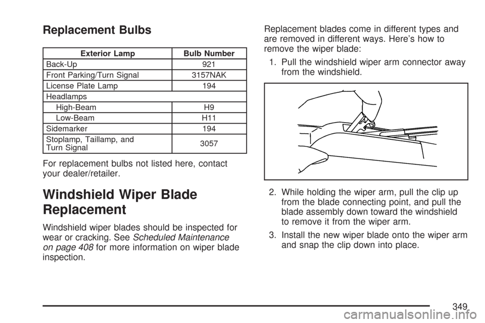
remove the wiper blade:
1. Pull the windshield wiper arm connector away
from the windshield.
2. While holding the wiper arm, pull the clip up
from the blade connecting point, and pull the
blade assembly down toward the windshield
to remove it from the wiper arm.
3. Install the new wiper blade onto the wiper arm
and snap the clip down into place.
349
Page 350 of 460
To remove and replace the wiper blade element
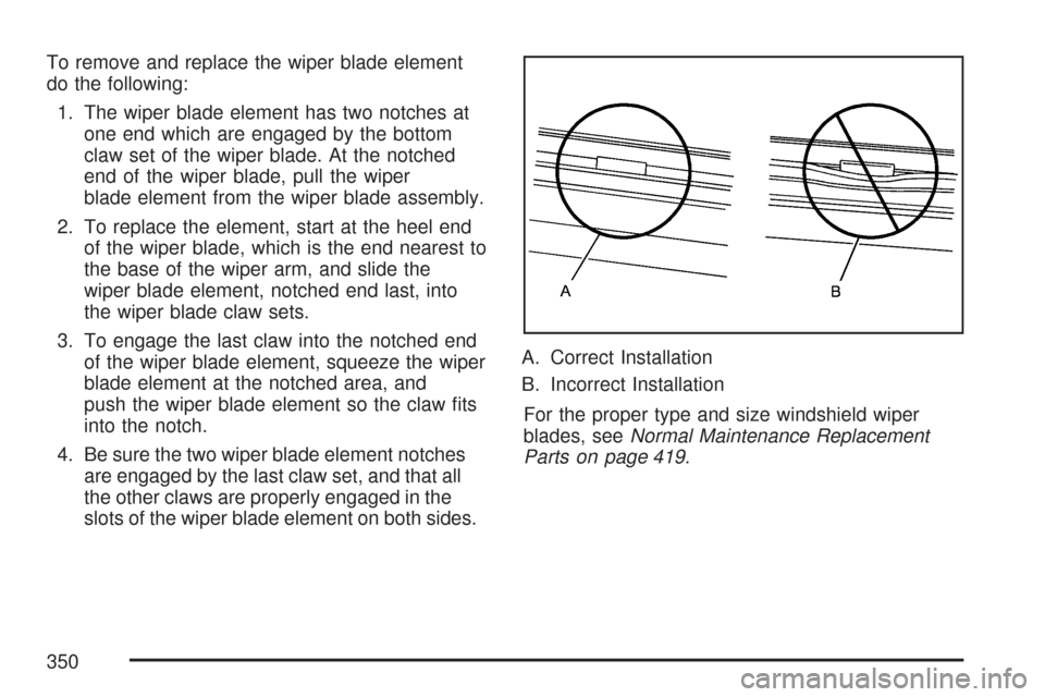
do the following:
1. The wiper blade element has two notches at
one end which are engaged by the bottom
claw set of the wiper blade. At the notched
end of the wiper blade, pull the wiper
blade element from the wiper blade assembly.
2. To replace the element, start at the heel end
of the wiper blade, which is the end nearest to
the base of the wiper arm, and slide the
wiper blade element, notched end last, into
the wiper blade claw sets.
3. To engage the last claw into the notched end
of the wiper blade element, squeeze the wiper
blade element at the notched area, and
push the wiper blade element so the claw �ts
into the notch.
4. Be sure the two wiper blade element notches
are engaged by the last claw set, and that all
the other claws are properly engaged in the
slots of the wiper blade element on both sides.A. Correct Installation
B. Incorrect Installation
For the proper type and size windshield wiper
blades, seeNormal Maintenance Replacement
Parts on page 419.
350