brake light CHEVROLET KODIAK 2005 User Guide
[x] Cancel search | Manufacturer: CHEVROLET, Model Year: 2005, Model line: KODIAK, Model: CHEVROLET KODIAK 2005Pages: 374, PDF Size: 5.46 MB
Page 103 of 374
Shifting Into NEUTRAL
Before shifting the transfer case to NEUTRAL, first
make sure the vehicle is parked so that it will not roll.
1. Set the parking brake.
2. Start the vehicle.
3. Put the transmission in NEUTRAL (N).
4. Shift the transfer case to Two-Wheel High.
5. Turn the transfer case knob all of the way past
Four-Wheel Low and hold it there for a minimum
of 10 seconds. The neutral indicator light will
come on.
6. Shift the transmission to REVERSE (R) for
one second, then shift the transmission to
DRIVE (D) for one second.
7. Turn the ignition to OFF.
8. Place the transmission shift lever in PARK. (P).
9. Turn the ignition to LOCK.
Shifting Out of NEUTRAL
To shift the transfer case out of NEUTRAL, do the
following:
1. Set the parking brake and apply the regular
brake pedal.
2. Turn the ignition to RUN with the engine off.
3. Put the transmission in NEUTRAL (N).
4. Turn the transfer case knob to the desired shift
position (Two-Wheel High, Four-Wheel High,
Four-Wheel Low).
5. After the transfer case has shifted out of NEUTRAL,
the indicator light will go out.
6. Release the parking brake.
7. Start the engine and shift the transmission lever to
the desired position.
Excessively shifting the transfer case into or out of the
different modes may cause the transfer case to enter the
shift protection mode. This will protect the transfer case
from possible damage and will only allow the transfer
case to respond to one shift per 10 seconds. The transfer
case may stay in this mode for up to three minutes.
2-37
Page 105 of 374
To set the hand lever parking brake, hold the regular
brake pedal down with your right foot. Pull up on
the handle with your right hand, until it stops.
If the ignition is on when the parking brake is set,
the brake system warning light will come on.
To release the foot pedal parking brake, hold the
regular brake pedal down. Pull the brake release handle,
located just above the parking brake pedal, to release
the parking brake.
To release the hand lever parking brake, hold the
regular brake pedal down and push down on the handle
until it stops.
If the ignition is on when the parking brake is released,
the brake system warning light will go off.
Propshaft Brake Burnish Procedure
It is recommended that the propshaft-mounted parking
brake be burnished as part of the new vehicle break-in.
The parking brake will work best after it has been
burnished following these instructions:
Make 10 stops, using the parking brake hand lever or
foot pedal, from 20 mph (32 km/h) about 2 1/2 miles
(4 km) apart. Between stops, drive the vehicle at
20 mph (32 km/h) to allow the brake to cool.Notice:Driving with the parking brake on can
damage the transmission and brake system parts.
Verify that the parking brake is fully released and the
brake warning light is off before driving.
Rear Wheel Park Brake Burnish
Procedure
It is recommended that the rear wheel mounted
parking brake be burnished as part of the new vehicle
break-in. The parking brake will work best after it
has been burnished following these instructions:
Make one or two stops using the parking brake hand
lever or foot pedal from 55 mph (92 km/h) to a stop
with moderate apply. Each stop should occur within
1/4 of a mile.
Notice:Driving with the parking brake on can
overheat the brake system and cause premature
wear or damage to brake system parts. Verify that
the parking brake is fully released and the brake
warning light is off before driving.
2-39
Page 106 of 374
Air Brake
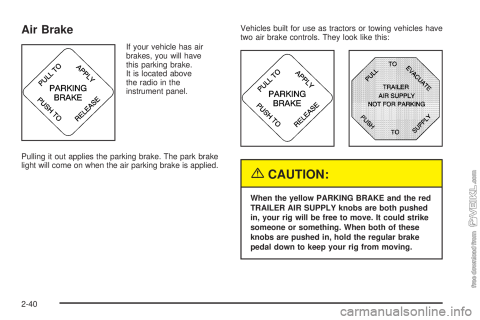
If your vehicle has air
brakes, you will have
this parking brake.
It is located above
the radio in the
instrument panel.
Pulling it out applies the parking brake. The park brake
light will come on when the air parking brake is applied.Vehicles built for use as tractors or towing vehicles have
two air brake controls. They look like this:
{CAUTION:
When the yellow PARKING BRAKE and the red
TRAILER AIR SUPPLY knobs are both pushed
in, your rig will be free to move. It could strike
someone or something. When both of these
knobs are pushed in, hold the regular brake
pedal down to keep your rig from moving.
2-40
Page 107 of 374
To charge a trailer’s air brake system do the following:
1. Move your vehicle into the proper position.
2. Apply the parking brake by pulling the yellow
parking brake knob out.
3. Hook up the trailer air system properly.
4. Get into the vehicle.
5. Push and hold down the regular brake pedal.
6. Push in both the yellow parking brake and the red
trailer air supply knobs. This will charge your
trailer’s air system.
After a few minutes, the trailer system should be fully
charged. When it is, the air pressure gage will show
about 125 to 135 psi (862 to 931 kPa).
For driving with a trailer, the yellow and red (if equipped)
knobs must be pushed in. When you are not pulling a
trailer, the red trailer air supply knob must be pulled out.
{CAUTION:
If you apply any one of the air brake parking
controls while the vehicle is moving, your rig
will stop suddenly. If you are not ready for this,
you or others could be injured. Do not apply any
one of these controls while you are driving,
unless you have to make an emergency stop.
If the air pressure drops below 60 to 70 psi
(413 to 482 kPa), the primary brake light and warning
buzzer will come on. If the air pressure drops to
35 to 45 psi (241 to 310 kPa), the red trailer air supply
knob will automatically pop out and apply the spring
brakes on the trailer.
If the air pressure drops to 35 to 45 psi (241 to 310 kPa),
the yellow park brake knob will automatically pop out
and apply the spring brakes on the truck or tractor.
2-41
Page 108 of 374
If you ever have a complete loss of air so that your air
brakes automatically apply, there is a way that the
tow operator can release the parking brakes to tow the
vehicle. SeeTowing Your Vehicle on page 4-35.
Air Suspension
Your vehicle may have the Hendrickson HAS Series
single-axle air suspension which is designed for a
single-axle on-highway use. This feature is available in
19,000 lb (8 613.3 kg), 21,000 lb (9 525.4 kg) and
23,000 lb (10 432.6 kg) capacities.
Rear Air Suspension Dump Control
If your vehicle is equipped with the Hendrickson HAS
Series single-axle air suspension, you may have
this control. The air suspension dump control allows the
operator to lower the deck height approximately
4.5 inches (11.5 cm) from the normal frame height.
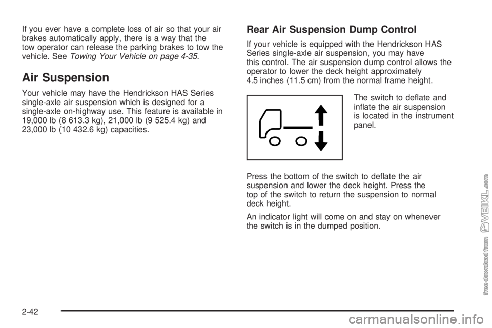
The switch to deflate and
inflate the air suspension
is located in the instrument
panel.
Press the bottom of the switch to deflate the air
suspension and lower the deck height. Press the
top of the switch to return the suspension to normal
deck height.
An indicator light will come on and stay on whenever
the switch is in the dumped position.
2-42
Page 115 of 374
Instrument Panel Overview...............................3-4
Hazard Warning Flashers................................3-6
Other Warning Devices...................................3-6
Horn.............................................................3-6
Tilt Wheel.....................................................3-7
Turn Signal/Multifunction Lever.........................3-7
Turn and Lane-Change Signals........................3-8
Headlamp High/Low-Beam Changer..................3-8
Windshield Wipers..........................................3-9
Windshield Washer.......................................3-10
Cruise Control..............................................3-10
Exterior Lamps.............................................3-14
Headlamps on Reminder................................3-15
Daytime Running Lamps (DRL).......................3-15
Marker Lamps..............................................3-16
Instrument Panel Brightness...........................3-16
Dome Lamps...............................................3-16
Entry Lighting...............................................3-17
Reading Lamps............................................3-17
Instrument Panel Switchbank..........................3-18
Accessory Power Outlets...............................3-19
Ashtrays and Cigarette Lighter........................3-20
Climate Controls............................................3-20
Climate Control System.................................3-20
Outlet Adjustment.........................................3-23
Rear Heating System....................................3-24Warning Lights, Gages, and Indicators............3-24
Instrument Panel Cluster................................3-25
Speedometer and Odometer...........................3-26
Trip Odometer..............................................3-26
Tachometer.................................................3-26
Engine Speed Limiter....................................3-26
Safety Belt Reminder Light.............................3-27
Safety Belt Reminder Tone............................3-27
Airbag Readiness Light..................................3-27
Airbag Off Light............................................3-28
Charging System Light..................................3-30
Voltmeter Gage............................................3-30
Service Transmission Warning Light................3-31
Range Inhibit Warning Indicator......................3-31
Brake System Warning Light..........................3-31
Anti-Lock Brake System Warning Light.............3-34
Trailer Anti-Lock Brake System Warning Light.....3-34
Engine Coolant Temperature Gage..................3-35
Low Coolant Warning Light............................3-35
Wait to Start Indicator (Diesel Engine).............3-36
Malfunction Indicator Lamp.............................3-36
Oil Pressure Gage........................................3-37
Low Oil Level Light.......................................3-38
Change Engine Oil Light................................3-38
Engine Overspeed Warning Light....................3-39
Engine Shutdown Warning Light.....................3-39
Section 3 Instrument Panel
3-1
Page 116 of 374
Transmission Temperature Gage.....................3-39
Exhaust Brake Indicator Light.........................3-40
Differential Lock Indicator Light.......................3-40
Reduced Engine Power Light.........................3-41
Highbeam On Light.......................................3-41
Daytime Running Lamps (DRL) Indicator Light.....3-41
Low Washer Fluid Warning Light.....................3-42
Check Gages Warning Light...........................3-42
Fuel Gage...................................................3-42
Water in Fuel Warning Light...........................3-43
Air Filter Restriction Indicator..........................3-43
Air Pressure Gage........................................3-44
Hourmeter Gage...........................................3-44Audio System(s).............................................3-44
Setting the Time...........................................3-45
AM-FM Radio...............................................3-45
Radio with Cassette......................................3-48
Radio with CD..............................................3-53
Theft-Deterrent Feature (Non-RDS Radios).......3-57
Radio Reception...........................................3-57
Care of the Cassette Tape Player...................3-58
Care of Your CDs.........................................3-59
Care of the CD Player...................................3-59
Fixed Mast Antenna......................................3-59
Chime Level Adjustment................................3-59
Section 3 Instrument Panel
3-2
Page 119 of 374
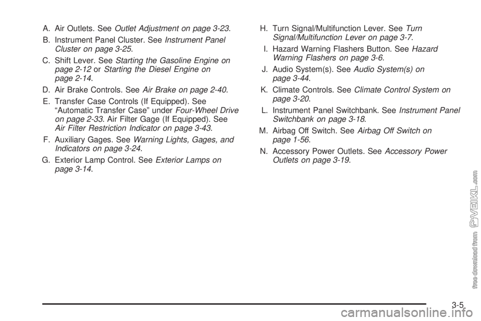
A. Air Outlets. SeeOutlet Adjustment on page 3-23.
B. Instrument Panel Cluster. SeeInstrument Panel
Cluster on page 3-25.
C. Shift Lever. SeeStarting the Gasoline Engine on
page 2-12orStarting the Diesel Engine on
page 2-14.
D. Air Brake Controls. SeeAir Brake on page 2-40.
E. Transfer Case Controls (If Equipped). See
“Automatic Transfer Case” underFour-Wheel Drive
on page 2-33. Air Filter Gage (If Equipped). See
Air Filter Restriction Indicator on page 3-43.
F. Auxiliary Gages. SeeWarning Lights, Gages, and
Indicators on page 3-24.
G. Exterior Lamp Control. SeeExterior Lamps on
page 3-14.H. Turn Signal/Multifunction Lever. SeeTurn
Signal/Multifunction Lever on page 3-7.
I. Hazard Warning Flashers Button. SeeHazard
Warning Flashers on page 3-6.
J. Audio System(s). SeeAudio System(s) on
page 3-44.
K. Climate Controls. SeeClimate Control System on
page 3-20.
L. Instrument Panel Switchbank. SeeInstrument Panel
Switchbank on page 3-18.
M. Airbag Off Switch. SeeAirbag Off Switch on
page 1-56.
N. Accessory Power Outlets. SeeAccessory Power
Outlets on page 3-19.
3-5
Page 127 of 374
Reducing Speed While Using Cruise
Control
Press in the button at the end of the lever until you
reach the lower speed you want, then release it.
To slow down in very small amounts, tap the button
briefly. Each time you do this, you’ll go 1 mph (1.6 km/h)
slower.
Passing Another Vehicle While Using
Cruise Control
Use the accelerator pedal to increase your speed.
When you take your foot off the pedal, your vehicle will
slow down to the cruise control speed you set earlier.
Using Cruise Control on Hills
How well your cruise control will work on hills depends
upon your speed, load and the steepness of the
hills. When going up steep hills, you may want to step
on the accelerator pedal to maintain your speed.
When going downhill, you may have to brake or shift to
a lower gear to keep your speed down. Of course,
applying the brake or clutch takes you out of cruise
control. Many drivers find this to be too much trouble
and don’t use cruise control on steep hills.
Ending Cruise Control
There are four different ways to turn off the cruise
control:
•Step lightly on the brake pedal (manual and
automatic transmissions).
•Press the clutch pedal to the floor (manual
transmissions).
•Move the cruise switch to off, or
•Shift the transmission to NEUTRAL (N).
Erasing Speed Memory
When you turn off the ignition, your cruise control set
speed memory is erased.
3-13
Page 129 of 374
Headlamps on Reminder
If you have this system, a tone will sound when your
headlamps and/or parking lamps are turned on and your
ignition is in LOCK or ACCESSORY.
Daytime Running Lamps (DRL)
Daytime Running Lamps (DRL) can make it easier for
others to see the front of your vehicle during the
day. DRL can be helpful in many different driving
conditions, but they can be especially helpful in the short
periods after dawn and before sunset. Fully functional
daytime running lamps are required on all vehicles
first sold in Canada.
The DRL system will make your headlamps come on
at reduced brightness when the following conditions
are met:
•The ignition is on,
•the exterior lamp control is off, and
•the parking brake is released.When the DRL are on, only your headlamps will be on.
The taillamps, sidemarker and other lamps won’t be
on. Your instrument panel won’t be lit up either.
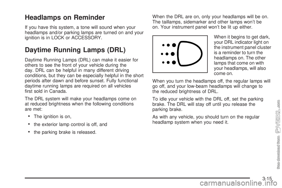
When it begins to get dark,
your DRL indicator light on
the instrument panel cluster
is a reminder to turn the
headlamps on. The other
lamps that come on with
your headlamps, will also
come on.
When you turn the headlamps off, the regular lamps will
go off, and your low-beam headlamps will change to
the reduced brightness of DRL.
To idle your vehicle with the DRL off, set the parking
brake. The DRL will stay off until you release the
parking brake.
As with any vehicle, you should turn on the regular
headlamp system when you need it.
3-15